Technical Information · issue 37 of 2000
New Sales designations for 020 and 020 T; Tank Cap
Model 020 T Chainsaws – Series 1129
IssueTI 37/2000
Engine family 1129
Part changes (1)
| Was | Becomes | What the bulletin says |
|---|---|---|
| 1129 120 0606 | 1129 120 0651 | The previous carburetors 1129 120 0606 and 1129 120 0650 have been replaced by carburetor 1129 120 0651. |
Full text
Page 1 of 9
Text of page 1 — search, copy, screen readers
Technical Information

                                                                                                        37.2000
Model 020 T Chainsaws – Series 1129

Contents
1. New Sales Designation
   for 020 T
2. Carburetor
   2.1 Construction
   2.2 Function
   2.3 Repairs / maintenance / standard setting
   2.4 Setting instructions for users
   2.5 Compensator connection
3. Tank Caps
4. Cylinder
5. Intake Air Preheating
6. Summary
7. Spare Parts

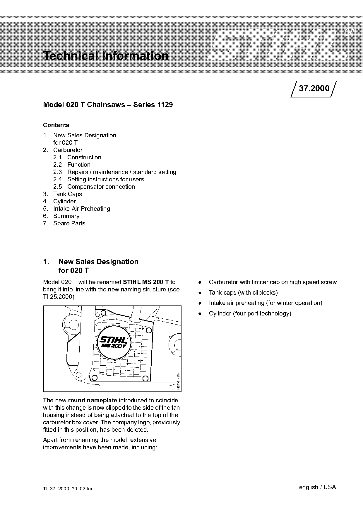
1.    New Sales Designation
      for 020 T
Model 020 T will be renamed STIHL MS 200 T to                     .   Carburetor with limiter cap on high speed screw
bring it into line with the new naming structure (see
                                                                  .   Tank caps (with cliplocks)
TI 25.2000).
                                                                  .   Intake air preheating (for winter operation)
                                                                  .   Cylinder (four-port technology)
                                                    142TI014 KN

The new round nameplate introduced to coincide
with this change is now clipped to the side of the fan
housing instead of being attached to the top of the
carburetor box cover. The company logo, previously
fitted in this position, has been deleted.
Apart from renaming the model, extensive
improvements have been made, including:

TI_37_2000_30_02.fm                                                                                     english / USA
Page 2 of 9
Text of page 2 — search, copy, screen readers
Page 2                                                                                   Technical Information 37.2000

2.     Carburetor
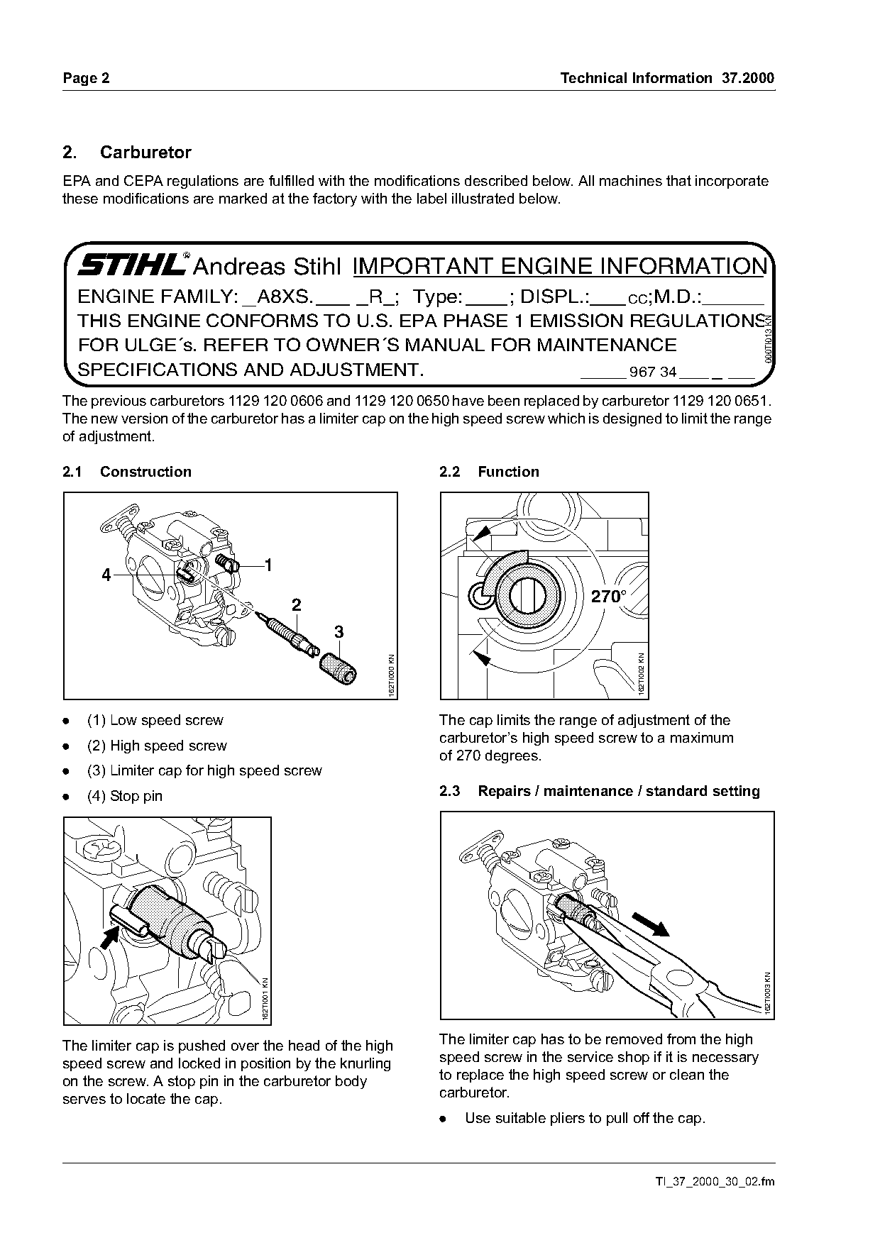
EPA and CEPA regulations are fulfilled with the modifications described below. All machines that incorporate
these modifications are marked at the factory with the label illustrated below.

                      Andreas Stihl IMPORTANT ENGINE INFORMATION
     ENGINE FAMILY: A8XS.     R ; Type:    ; DISPL.:   CC;M.D.:
     THIS ENGINE CONFORMS TO U.S. EPA PHASE 1 EMISSION REGULATIONS

                                                                                                                                     000TI013 KN
     FOR ULGE´s. REFER TO OWNER´S MANUAL FOR MAINTENANCE
     SPECIFICATIONS AND ADJUSTMENT.                    967 34

The previous carburetors 1129 120 0606 and 1129 120 0650 have been replaced by carburetor 1129 120 0651.
The new version of the carburetor has a limiter cap on the high speed screw which is designed to limit the range
of adjustment.

2.1    Construction                                                 2.2     Function

                                   1
        4
                                                                                               270°
                                              2
                                                  3                                                   162TI002 KN
                                                      162TI000 KN

.     (1) Low speed screw                                           The cap limits the range of adjustment of the
                                                                    carburetor’s high speed screw to a maximum
.     (2) High speed screw
                                                                    of 270 degrees.
.     (3) Limiter cap for high speed screw
.     (4) Stop pin                                                  2.3     Repairs / maintenance / standard setting
                                                                                                                                     162TI003 KN
                                162TI001 KN

The limiter cap is pushed over the head of the high                 The limiter cap has to be removed from the high
speed screw and locked in position by the knurling                  speed screw in the service shop if it is necessary
on the screw. A stop pin in the carburetor body                     to replace the high speed screw or clean the
serves to locate the cap.                                           carburetor.
                                                                    .     Use suitable pliers to pull off the cap.

                                                                                                                    TI_37_2000_30_02.fm
Page 3 of 9
Text of page 3 — search, copy, screen readers
Technical Information 37.2000                                                                        Page 3

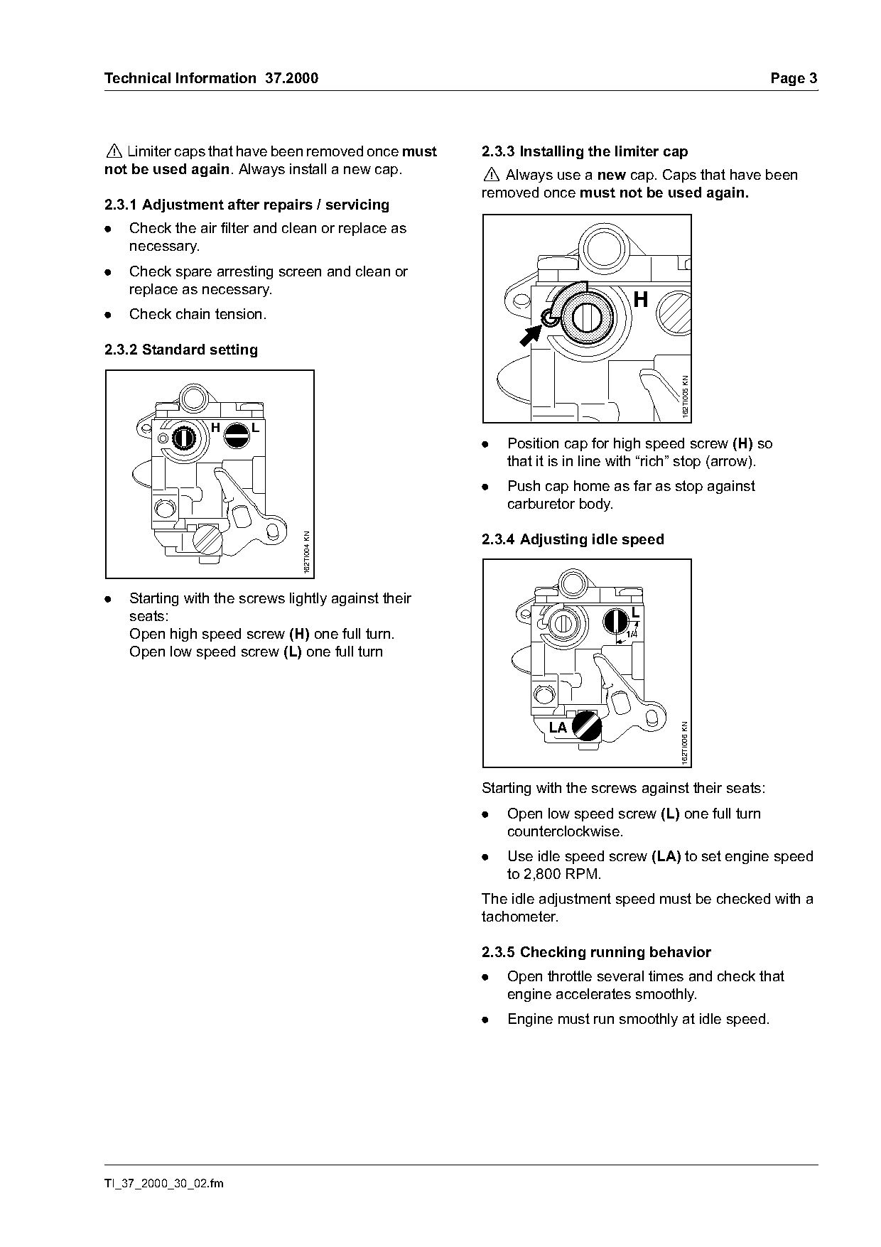
! Limiter caps that have been removed once must      2.3.3 Installing the limiter cap
not be used again. Always install a new cap.         ! Always use a new cap. Caps that have been
                                                     removed once must not be used again.
2.3.1 Adjustment after repairs / servicing
.   Check the air filter and clean or replace as
    necessary.
.   Check spare arresting screen and clean or
    replace as necessary.
                                                                             H
.   Check chain tension.

2.3.2 Standard setting

                                                                                      162TI005 KN
                 H     L
                                                     .   Position cap for high speed screw (H) so
                                                         that it is in line with “rich” stop (arrow).
                                                     .   Push cap home as far as stop against
                                                         carburetor body.

                                                     2.3.4 Adjusting idle speed
                                162TI004 KN

.   Starting with the screws lightly against their
    seats:                                                                   L
    Open high speed screw (H) one full turn.                                1/4

    Open low speed screw (L) one full turn

                                                                                     162TI006 KN


                                                     Starting with the screws against their seats:
                                                     .   Open low speed screw (L) one full turn
                                                         counterclockwise.
                                                     .   Use idle speed screw (LA) to set engine speed
                                                         to 2,800 RPM.
                                                     The idle adjustment speed must be checked with a
                                                     tachometer.

                                                     2.3.5 Checking running behavior
                                                     .   Open throttle several times and check that
                                                         engine accelerates smoothly.
                                                     .   Engine must run smoothly at idle speed.

TI_37_2000_30_02.fm
Page 4 of 9
Text of page 4 — search, copy, screen readers
Page 4                                                               Technical Information 37.2000

2.4       Setting instructions for users

                          270°
                                 162TI002 KN

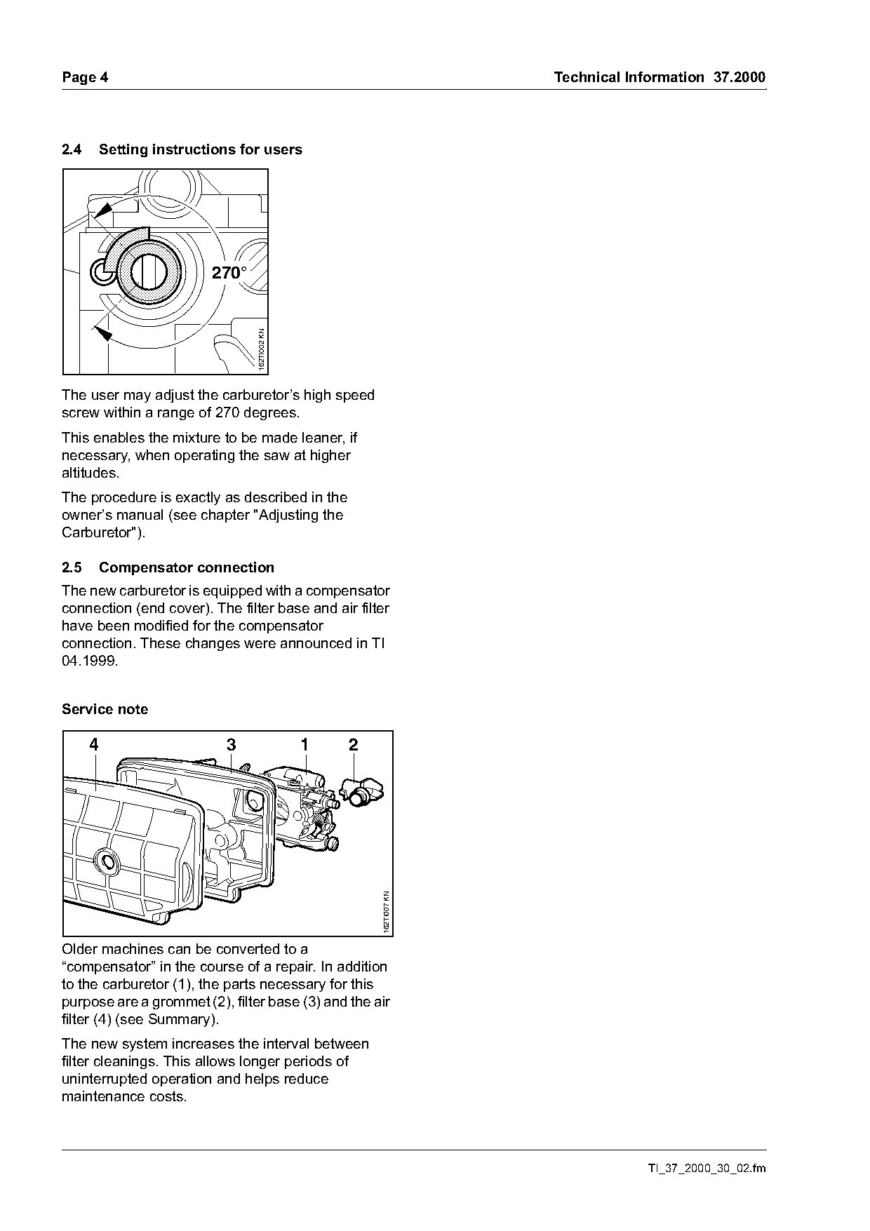
The user may adjust the carburetor’s high speed
screw within a range of 270 degrees.
This enables the mixture to be made leaner, if
necessary, when operating the saw at higher
altitudes.
The procedure is exactly as described in the
owner’s manual (see chapter "Adjusting the
Carburetor").

2.5       Compensator connection
The new carburetor is equipped with a compensator
connection (end cover). The filter base and air filter
have been modified for the compensator
connection. These changes were announced in TI
04.1999.

Service note

      4                     3                  1   2
                                                       162TI007 KN

Older machines can be converted to a
“compensator” in the course of a repair. In addition
to the carburetor (1), the parts necessary for this
purpose are a grommet (2), filter base (3) and the air
filter (4) (see Summary).
The new system increases the interval between
filter cleanings. This allows longer periods of
uninterrupted operation and helps reduce
maintenance costs.

                                                                                 TI_37_2000_30_02.fm
Page 5 of 9
Text of page 5 — search, copy, screen readers
Technical Information 37.2000                                                                                  Page 5

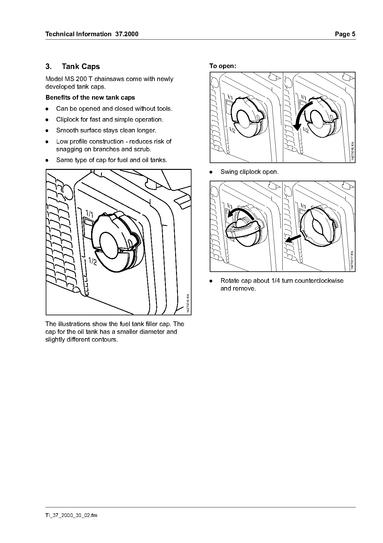
3.    Tank Caps                                                      To open:

Model MS 200 T chainsaws come with newly
developed tank caps.
Benefits of the new tank caps                                              1/1                      1/1

.    Can be opened and closed without tools.
.    Cliplock for fast and simple operation.
.    Smooth surface stays clean longer.                                     1/2                      1/2

.    Low profile construction - reduces risk of

                                                                                                                        142TI016 KN
     snagging on branches and scrub.
.    Same type of cap for fuel and oil tanks.
                                                                     .   Swing cliplock open.

                                                                           1/1                      1/1
               1/1

                                                                            1/2

                                                                                                                      142TI017 KN
                1/2

                                                                     .   Rotate cap about 1/4 turn counterclockwise
                                                                         and remove.
                                                       142TI015 KN

The illustrations show the fuel tank filler cap. The
cap for the oil tank has a smaller diameter and
slightly different contours.

TI_37_2000_30_02.fm
Page 6 of 9
Text of page 6 — search, copy, screen readers
Page 6                                                                                 Technical Information 37.2000

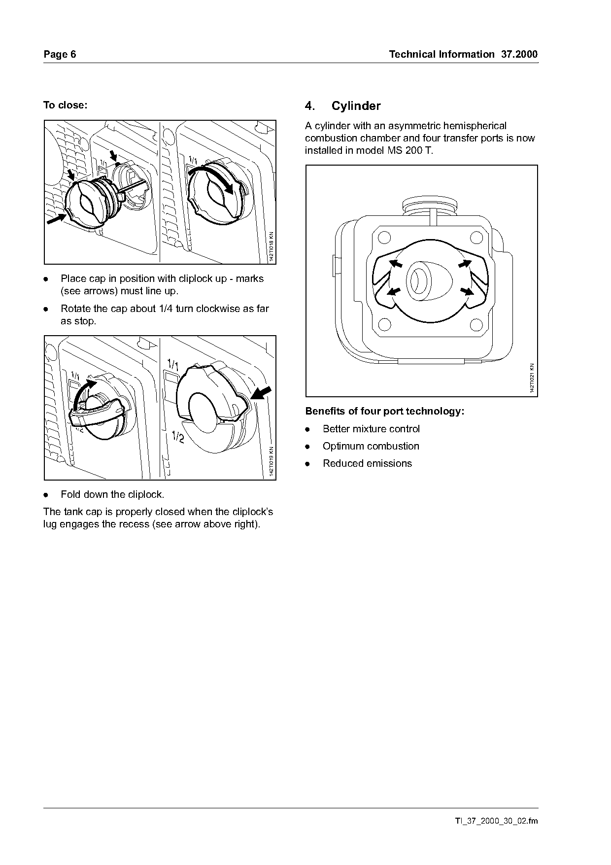
To close:                                                          4.    Cylinder
                                                                   A cylinder with an asymmetric hemispherical
                                                                   combustion chamber and four transfer ports is now
                                                                   installed in model MS 200 T.
             1/1                     1/1

                                                     142TI018 KN
.   Place cap in position with cliplock up - marks
    (see arrows) must line up.
.   Rotate the cap about 1/4 turn clockwise as far
    as stop.

                              1/1

                                                                                                                    142TI021 KN
      1/1

                                                                   Benefits of four port technology:
       1/2                                                         .    Better mixture control
                               1/2
                                                                   .    Optimum combustion
                                                     142TI019 KN

                                                                   .    Reduced emissions

.   Fold down the cliplock.
The tank cap is properly closed when the cliplock’s
lug engages the recess (see arrow above right).

                                                                                                   TI_37_2000_30_02.fm
Page 7 of 9
Text of page 7 — search, copy, screen readers
Technical Information 37.2000                                                                                Page 7

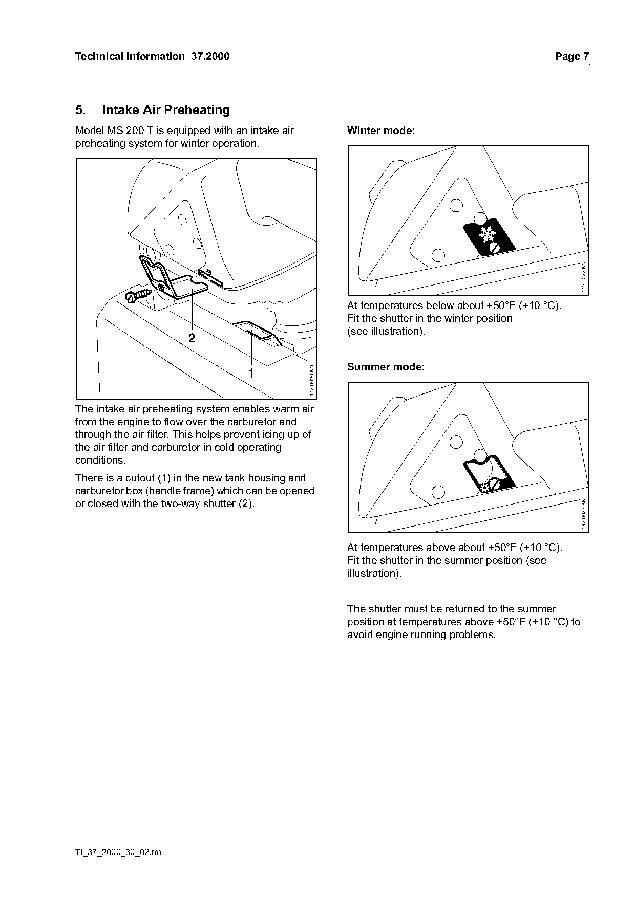
5.    Intake Air Preheating
Model MS 200 T is equipped with an intake air                      Winter mode:
preheating system for winter operation.

                                                                                                                      142TI022 KN
                                                                   At temperatures below about +50°F (+10 °C).
                                                                   Fit the shutter in the winter position
                                                                   (see illustration).
                         2

                                                                   Summer mode:
                                                     142TI020 KN


The intake air preheating system enables warm air
from the engine to flow over the carburetor and
through the air filter. This helps prevent icing up of
the air filter and carburetor in cold operating
conditions.
There is a cutout (1) in the new tank housing and
carburetor box (handle frame) which can be opened
or closed with the two-way shutter (2).

                                                                                                                      142TI023 KN
                                                                   At temperatures above about +50°F (+10 °C).
                                                                   Fit the shutter in the summer position (see
                                                                   illustration).

                                                                   The shutter must be returned to the summer
                                                                   position at temperatures above +50°F (+10 °C) to
                                                                   avoid engine running problems.

TI_37_2000_30_02.fm
Page 8 of 9
Text of page 8 — search, copy, screen readers
Page 8                                                                        Technical Information 37.2000

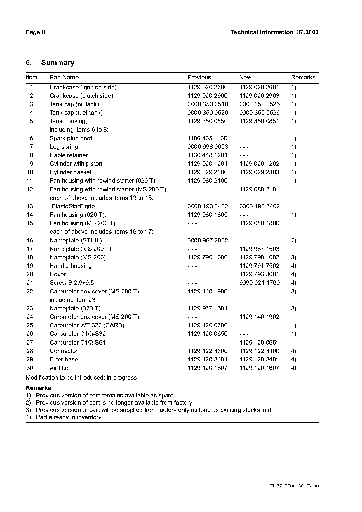
6.     Summary
Item     Part Name                                           Previous            New                 Remarks
 1       Crankcase (ignition side)                            1129 020 2600      1129 020 2601       1)
 2       Crankcase (clutch side)                              1129 020 2900      1129 020 2903       1)
 3       Tank cap (oil tank)                                  0000 350 0510      0000 350 0525       1)
 4       Tank cap (fuel tank)                                 0000 350 0520      0000 350 0526       1)
 5       Tank housing;                                        1129 350 0850      1129 350 0851       1)
         including items 6 to 8:
 6       Spark plug boot                                      1106 405 1100      ---                 1)
 7       Leg spring                                           0000 998 0603      ---                 1)
 8       Cable retainer                                       1130 448 1201      ---                 1)
 9       Cylinder with piston                                 1129 020 1201      1129 020 1202       1)
10       Cylinder gasket                                      1129 029 2300      1129 029 2303       1)
11       Fan housing with rewind starter (020 T);             1129 080 2100      ---                 1)
12       Fan housing with rewind starter (MS 200 T);          ---                1129 080 2101
         each of above includes items 13 to 15:
13       “ElastoStart“ grip                                   0000 190 3402      0000 190 3402
14       Fan housing (020 T);                                 1129 080 1805      ---                 1)
15       Fan housing (MS 200 T);                              ---                1129 080 1800
         each of above includes items 16 to 17:
16       Nameplate (STIHL)                                   0000 967 2032       ---                 2)
17       Nameplate (MS 200 T)                                ---                 1129 967 1503
18       Nameplate (MS 200)                                  1129 790 1000       1129 790 1002       3)
19       Handle housing                                      ---                 1129 791 7502       4)
20       Cover                                               ---                 1129 793 3001       4)
21       Screw B 2.9x9.5                                     ---                 9099 021 1760       4)
22       Carburetor box cover (MS 200 T);                    1129 140 1900       ---                 3)
         including item 23:
23       Nameplate (020 T)                                    1129 967 1501      ---                 3)
24       Carburetor box cover (MS 200 T)                      ---                1129 140 1902
25       Carburetor WT-326 (CARB)                             1129 120 0606      ---                 1)
26       Carburetor C1Q-S32                                   1129 120 0650      ---                 1)
27       Carburetor C1Q-S61                                   ---                1129 120 0651
28       Connector                                            1129 122 3300      1129 122 3300       4)
29       Filter base                                          1129 120 3401      1129 120 3401       4)
30       Air filter                                           1129 120 1607      1129 120 1607       4)
Modification to be introduced: in progress
Remarks
1) Previous version of part remains available as spare
2) Previous version of part is no longer available from factory
3) Previous version of part will be supplied from factory only as long as existing stocks last
4) Part already in inventory

                                                                                             TI_37_2000_30_02.fm
Page 9 of 9

Text of page 9 — search, copy, screen readers
Technical Information 37.2000                                                      Page 9

7.    Spare Parts
A separate illustrated parts list is available for the
new MS 200 T chainsaw. The parts list is included in
the next issue (01.2001) on microfiche and CD-
ROM

Last Technical Information on model 020 T: 17.1999

© 2000 Andreas Stihl AG & Co.                            Technical Documentation
  Waiblingen                                             D1/MTK-al                  7081

TI_37_2000_30_02.fm
Most of these PDFs embed fonts with a shifted character map, so the text above was recovered rather than copied — read it as a faithful but imperfect transcription, and treat the page image above each block as the authority where the two disagree — the figures exist only there, because they are vector drawings that text extraction cannot keep.