Technical Information · issue 46 of 2000
Angle drive; Cutting blades; End guard (special ac
IssueTI 46/2000
Part changes (1)
| Was | Becomes | What the bulletin says |
|---|---|---|
| 9503 003 9850 | 9503 003 9853 | bearing (previously 9503 003 9850) will be replaced by ball bearing 9503 003 9853. |
Full text
Page 1 of 6
Text of page 1 — search, copy, screen readers
Technical Information

                                                                                                              46.2000
STIHL HL 75, HL 75 K                 Hedge Trimmers                         - Series 4230
STIHL FH 75                          Power Scythe                           - Series 4230
STIHL HL 45                          Hedge Trimmer                          - Series 4232
STIHL HL 73, HL 73 K                 Hedge Trimmers                         - Series 4235

Contents
1. Angle drive
2. Cutting blades
3. End guard (special accessory)

1.    Angle drive
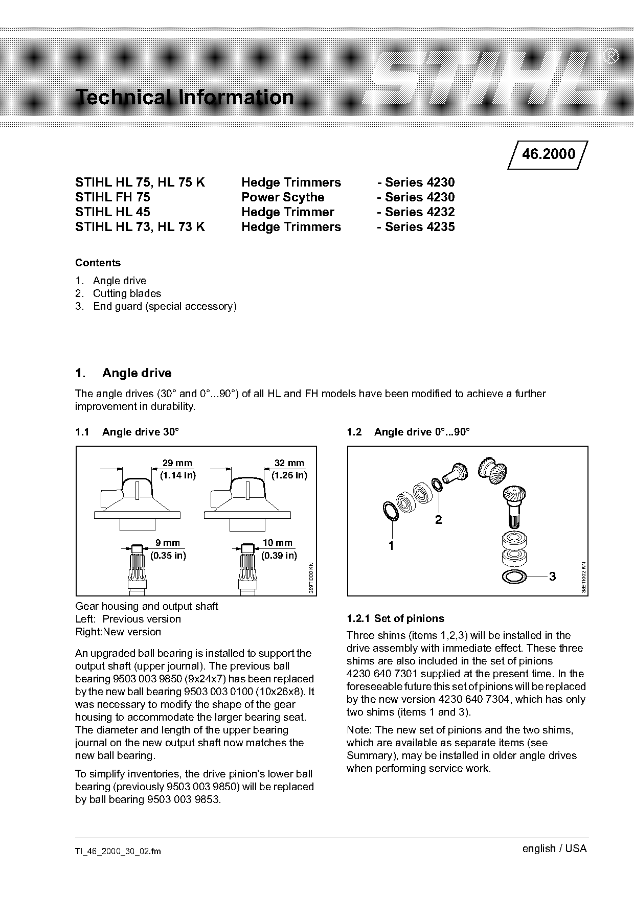
The angle drives (30° and 0°...90°) of all HL and FH models have been modified to achieve a further
improvement in durability.

1.1   Angle drive 30°                                                 1.2   Angle drive 0°...90°

                    29 mm                    32 mm
                   (1.14 in)                (1.26 in)

                                                                                          2
                 9 mm                     10 mm                                1
                (0.35 in)                 (0.39 in)

                                                                                                                           389TI002 KN
                                                        389TI000 KN


Gear housing and output shaft
Left: Previous version                                                1.2.1 Set of pinions
Right:New version                                                     Three shims (items 1,2,3) will be installed in the
An upgraded ball bearing is installed to support the                  drive assembly with immediate effect. These three
output shaft (upper journal). The previous ball                       shims are also included in the set of pinions
bearing 9503 003 9850 (9x24x7) has been replaced                      4230 640 7301 supplied at the present time. In the
by the new ball bearing 9503 003 0100 (10x26x8). It                   foreseeable future this set of pinions will be replaced
was necessary to modify the shape of the gear                         by the new version 4230 640 7304, which has only
housing to accommodate the larger bearing seat.                       two shims (items 1 and 3).
The diameter and length of the upper bearing                          Note: The new set of pinions and the two shims,
journal on the new output shaft now matches the                       which are available as separate items (see
new ball bearing.                                                     Summary), may be installed in older angle drives
To simplify inventories, the drive pinion’s lower ball                when performing service work.
bearing (previously 9503 003 9850) will be replaced
by ball bearing 9503 003 9853.

TI_46_2000_30_02.fm                                                                                           english / USA
Page 2 of 6
Text of page 2 — search, copy, screen readers
Page 2                                                                                   Technical Information 46.2000

                                                                                                                           389TI009 KN
                                                   389TI003 KN
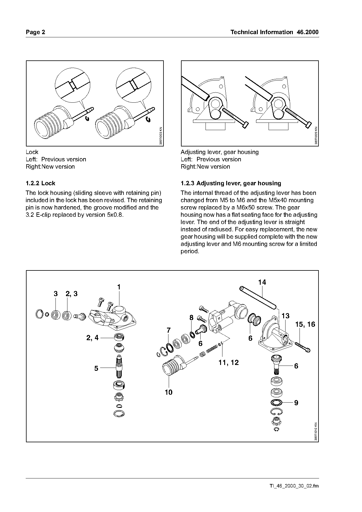
Lock                                                                  Adjusting lever, gear housing
Left: Previous version                                                Left: Previous version
Right:New version                                                     Right:New version

1.2.2 Lock                                                            1.2.3 Adjusting lever, gear housing
The lock housing (sliding sleeve with retaining pin)                  The internal thread of the adjusting lever has been
included in the lock has been revised. The retaining                  changed from M5 to M6 and the M5x40 mounting
pin is now hardened, the groove modified and the                      screw replaced by a M6x50 screw. The gear
3.2 E-clip replaced by version 5x0.8.                                 housing now has a flat seating face for the adjusting
                                                                      lever. The end of the adjusting lever is straight
                                                                      instead of radiused. For easy replacement, the new
                                                                      gear housing will be supplied complete with the new
                                                                      adjusting lever and M6 mounting screw for a limited
                                                                      period.

                                                                                                    14
                                  1
          3    2, 3

                                                                         8                                   13
                                                                                                                  15, 16
                                                                 7
                         2, 4                                                                   6
                                                                             6

                                                                                    11, 12                        6
                           5

                                                                 10
                                                                                                                  9
                                                                                                                          389TI010 KN

                                                                                                         TI_46_2000_30_02.fm
Page 3 of 6
Text of page 3 — search, copy, screen readers
Technical Information 46.2000                                                                           Page 3

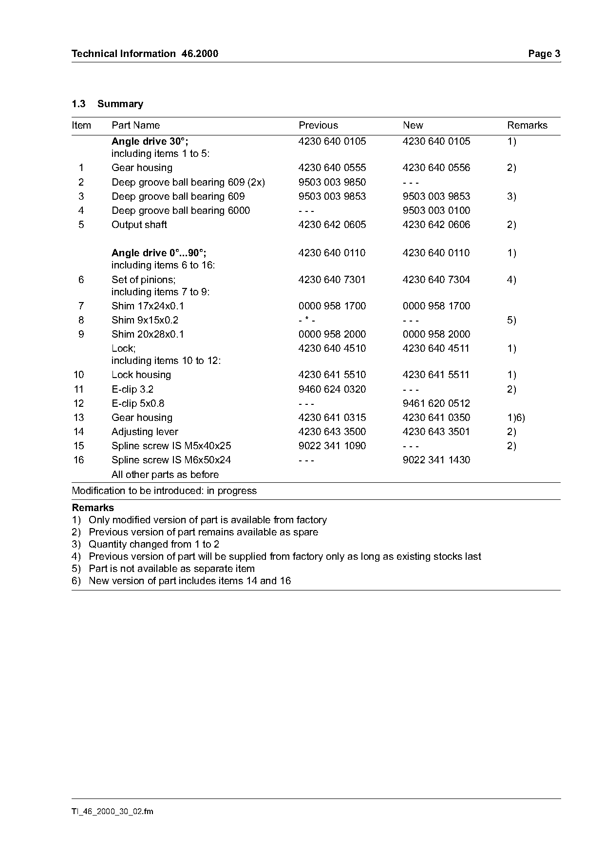
1.3    Summary

Item     Part Name                                  Previous                New                  Remarks
         Angle drive 30°;                           4230 640 0105           4230 640 0105        1)
         including items 1 to 5:
 1       Gear housing                               4230 640 0555           4230 640 0556        2)
 2       Deep groove ball bearing 609 (2x)          9503 003 9850           ---
 3       Deep groove ball bearing 609               9503 003 9853           9503 003 9853        3)
 4       Deep groove ball bearing 6000              ---                     9503 003 0100
 5       Output shaft                               4230 642 0605           4230 642 0606        2)

         Angle drive 0°...90°;                      4230 640 0110           4230 640 0110        1)
         including items 6 to 16:
 6       Set of pinions;                            4230 640 7301           4230 640 7304        4)
         including items 7 to 9:
 7       Shim 17x24x0.1                             0000 958 1700           0000 958 1700
 8       Shim 9x15x0.2                              -*-                     ---                  5)
 9       Shim 20x28x0.1                             0000 958 2000           0000 958 2000
         Lock;                                      4230 640 4510           4230 640 4511        1)
         including items 10 to 12:
10       Lock housing                               4230 641 5510           4230 641 5511        1)
11       E-clip 3.2                                 9460 624 0320           ---                  2)
12       E-clip 5x0.8                               ---                     9461 620 0512
13       Gear housing                               4230 641 0315           4230 641 0350        1)6)
14       Adjusting lever                            4230 643 3500           4230 643 3501        2)
15       Spline screw IS M5x40x25                   9022 341 1090           ---                  2)
16       Spline screw IS M6x50x24                   ---                     9022 341 1430
         All other parts as before
Modification to be introduced: in progress
Remarks
1) Only modified version of part is available from factory
2) Previous version of part remains available as spare
3) Quantity changed from 1 to 2
4) Previous version of part will be supplied from factory only as long as existing stocks last
5) Part is not available as separate item
6) New version of part includes items 14 and 16

TI_46_2000_30_02.fm
Page 4 of 6
Text of page 4 — search, copy, screen readers
Page 4                                                                     Technical Information 46.2000

2.    Cutting blades
The cutting blades (HL) and cutting blade assembly
(HL and FH) have been optimized to further
enhance performance and simplify servicing
procedures.

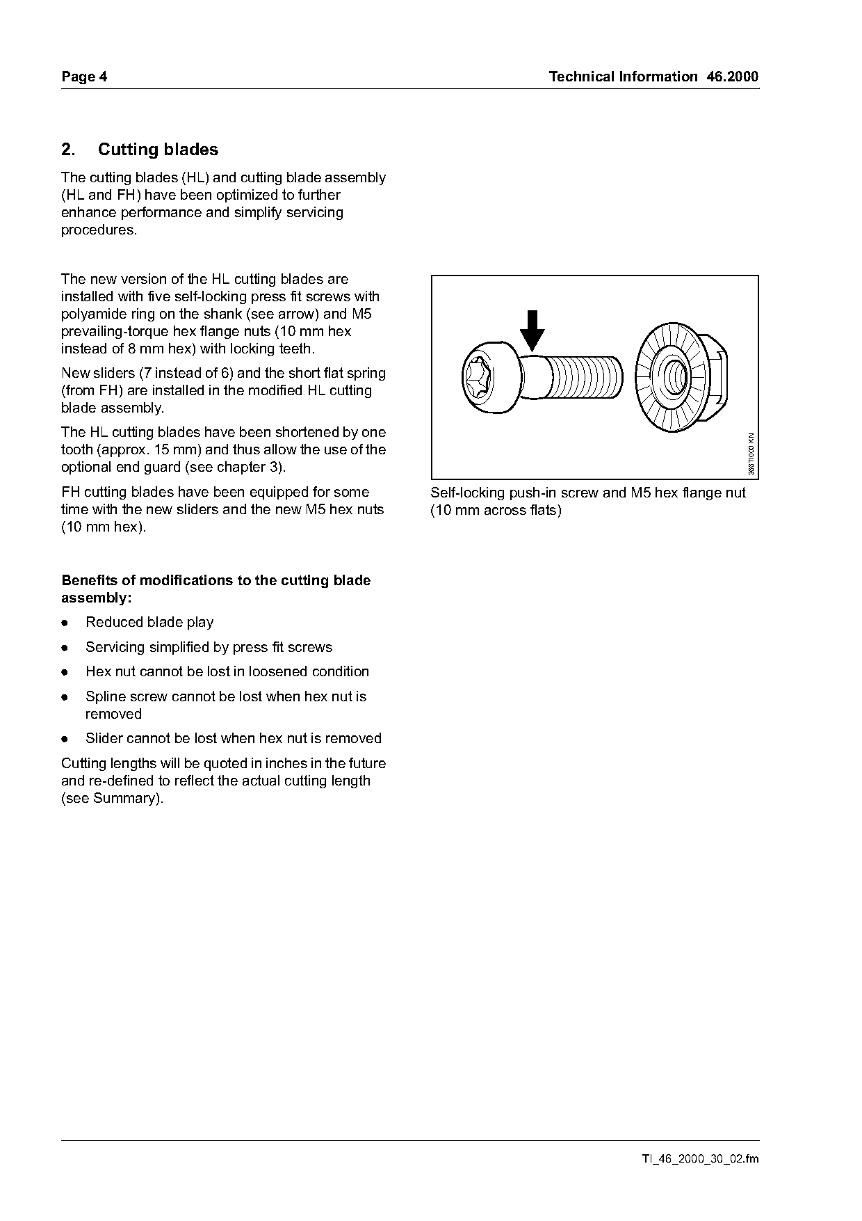
The new version of the HL cutting blades are
installed with five self-locking press fit screws with
polyamide ring on the shank (see arrow) and M5
prevailing-torque hex flange nuts (10 mm hex
instead of 8 mm hex) with locking teeth.
New sliders (7 instead of 6) and the short flat spring
(from FH) are installed in the modified HL cutting
blade assembly.
The HL cutting blades have been shortened by one

                                                                                                            366TI000 KN
tooth (approx. 15 mm) and thus allow the use of the
optional end guard (see chapter 3).
FH cutting blades have been equipped for some            Self-locking push-in screw and M5 hex flange nut
time with the new sliders and the new M5 hex nuts        (10 mm across flats)
(10 mm hex).

Benefits of modifications to the cutting blade
assembly:
.    Reduced blade play
.    Servicing simplified by press fit screws
.    Hex nut cannot be lost in loosened condition
.    Spline screw cannot be lost when hex nut is
     removed
.    Slider cannot be lost when hex nut is removed
Cutting lengths will be quoted in inches in the future
and re-defined to reflect the actual cutting length
(see Summary).

                                                                                         TI_46_2000_30_02.fm
Page 5 of 6
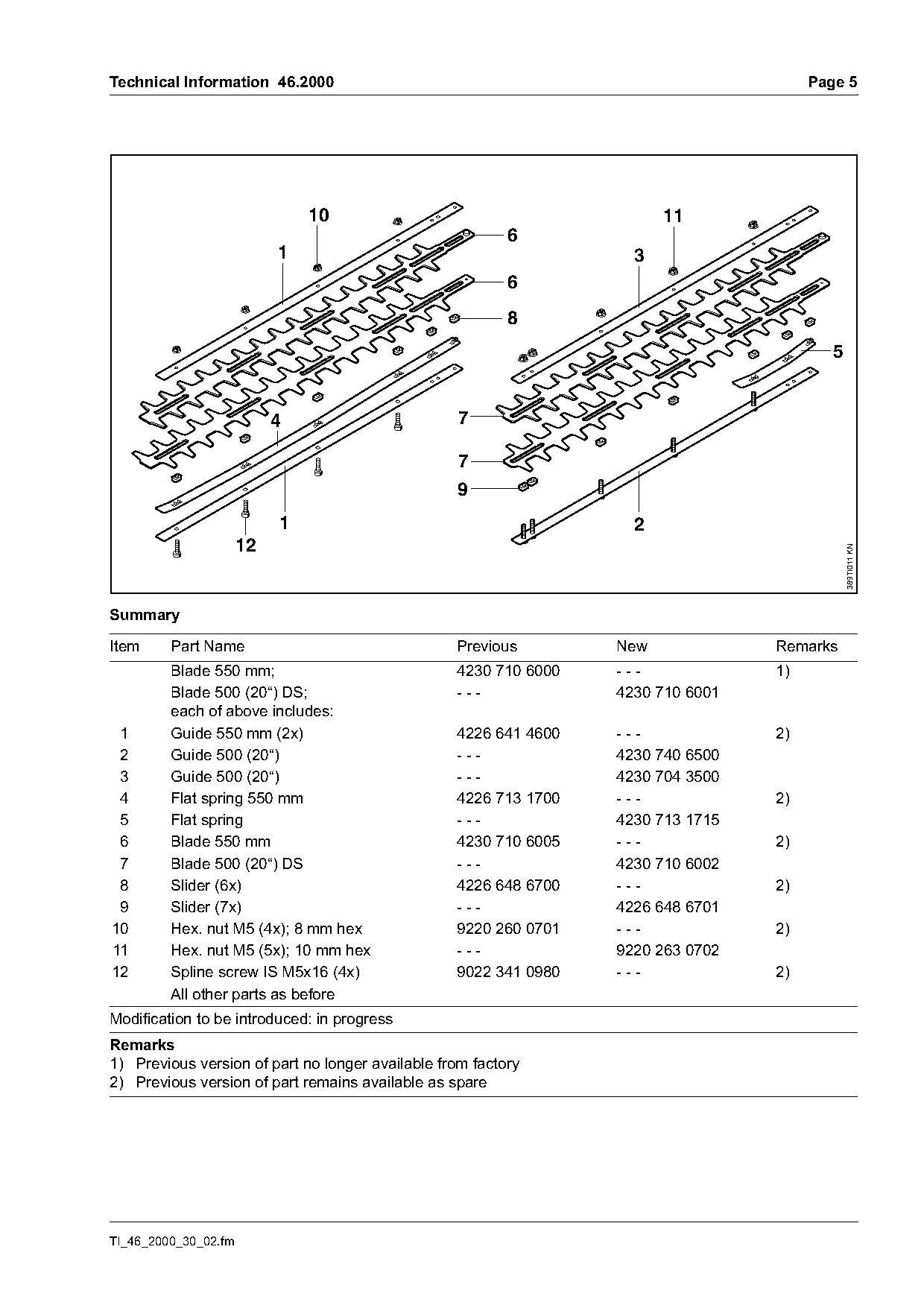
Text of page 5 — search, copy, screen readers
Technical Information 46.2000                                                          Page 5

                               10                                       11
                                                          6
                           1                                        3
                                                          6
                                                          8
                                                                                          5

                           4                       7

                                                  7
                                                  9
                           1                                        2
                      12

                                                                                              389TI011 KN
Summary

Item     Part Name                                Previous        New             Remarks
         Blade 550 mm;                            4230 710 6000   ---             1)
         Blade 500 (20“) DS;                      ---             4230 710 6001
         each of above includes:
 1       Guide 550 mm (2x)                        4226 641 4600   ---             2)
 2       Guide 500 (20“)                          ---             4230 740 6500
 3       Guide 500 (20“)                          ---             4230 704 3500
 4       Flat spring 550 mm                       4226 713 1700   ---             2)
 5       Flat spring                              ---             4230 713 1715
 6       Blade 550 mm                             4230 710 6005   ---             2)
 7       Blade 500 (20“) DS                       ---             4230 710 6002
 8       Slider (6x)                              4226 648 6700   ---             2)
 9       Slider (7x)                              ---             4226 648 6701
10       Hex. nut M5 (4x); 8 mm hex               9220 260 0701   ---             2)
11       Hex. nut M5 (5x); 10 mm hex              ---             9220 263 0702
12       Spline screw IS M5x16 (4x)               9022 341 0980   ---             2)
         All other parts as before
Modification to be introduced: in progress
Remarks
1) Previous version of part no longer available from factory
2) Previous version of part remains available as spare

TI_46_2000_30_02.fm
Page 6 of 6
Text of page 6 — search, copy, screen readers
Page 6                                                                   Technical Information 46.2000

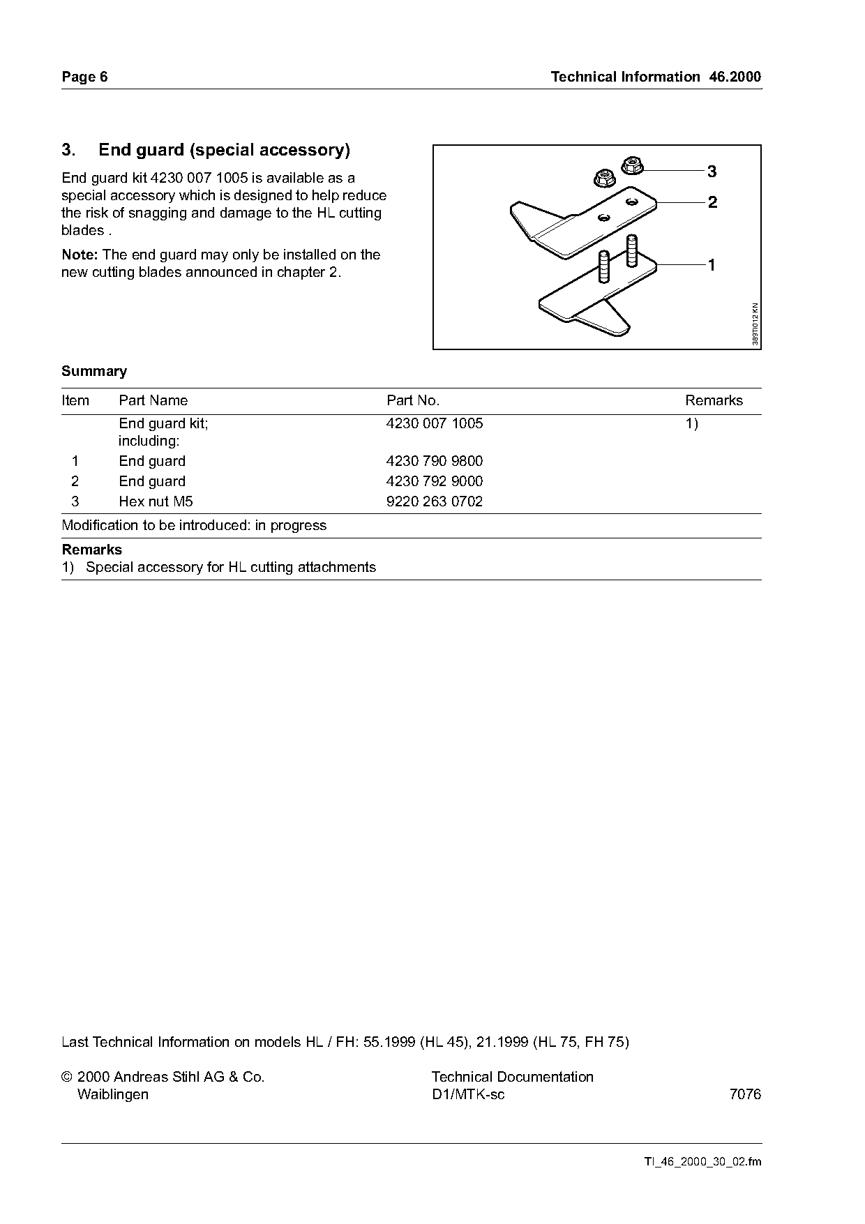
3.     End guard (special accessory)
End guard kit 4230 007 1005 is available as a                                                      3
special accessory which is designed to help reduce
                                                                                                   2
the risk of snagging and damage to the HL cutting
blades .
Note: The end guard may only be installed on the
new cutting blades announced in chapter 2.                                                         1

                                                                                                         389TI012 KN
Summary

Item     Part Name                                 Part No.                                   Remarks
         End guard kit;                            4230 007 1005                              1)
         including:
 1       End guard                                 4230 790 9800
 2       End guard                                 4230 792 9000
 3       Hex nut M5                                9220 263 0702
Modification to be introduced: in progress
Remarks
1) Special accessory for HL cutting attachments

Last Technical Information on models HL / FH: 55.1999 (HL 45), 21.1999 (HL 75, FH 75)

© 2000 Andreas Stihl AG & Co.                            Technical Documentation
  Waiblingen                                             D1/MTK-sc                                     7076

                                                                                        TI_46_2000_30_02.fm
Most of these PDFs embed fonts with a shifted character map, so the text above was recovered rather than copied — read it as a faithful but imperfect transcription, and treat the page image above each block as the authority where the two disagree — the figures exist only there, because they are vector drawings that text extraction cannot keep.