Technical Information · issue 48 of 2000
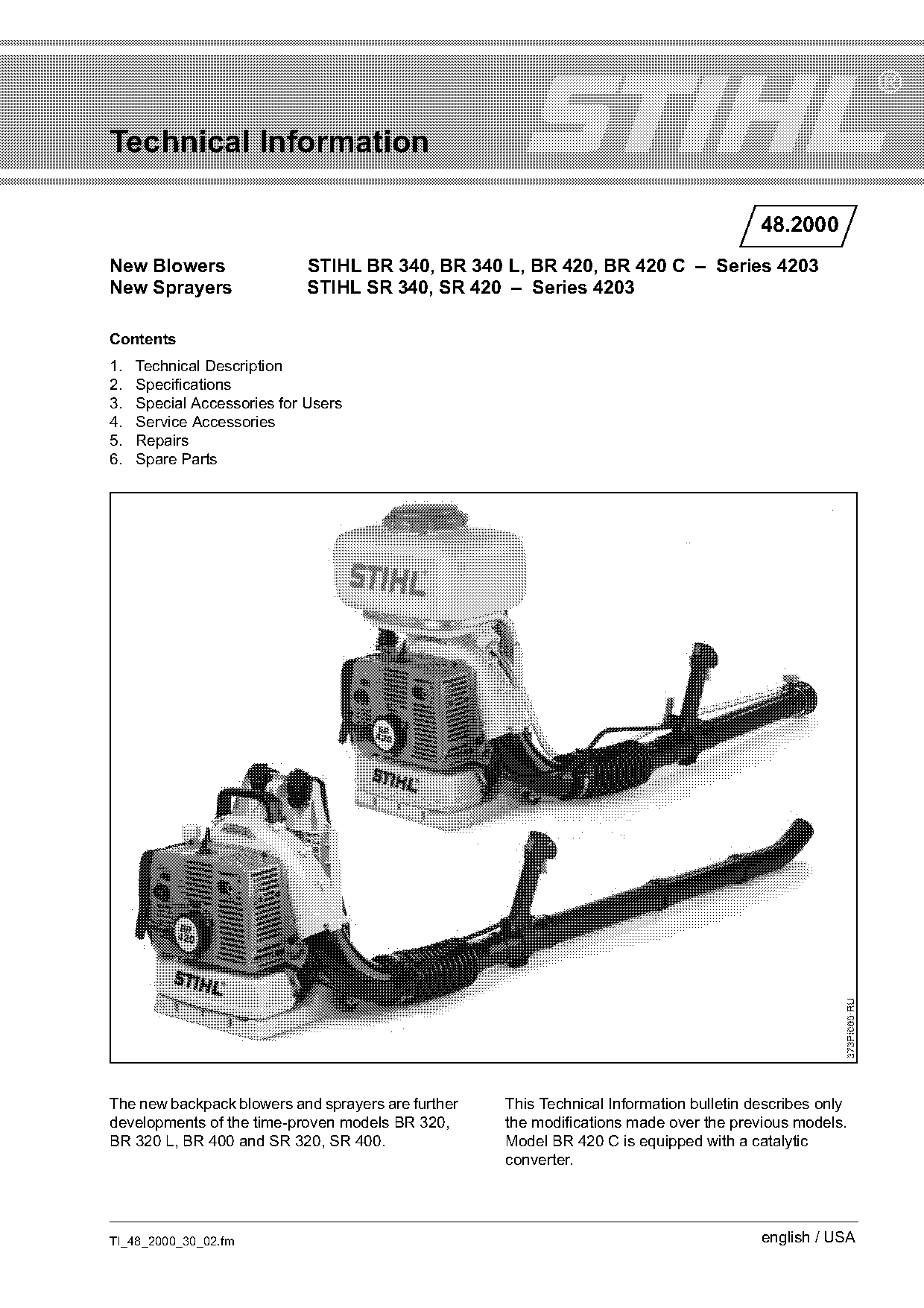
New Blowers, New Sprayers
Model: BR 340, BR 340 L, SR 340 BR 420, BR 420 C, SR 420
IssueTI 48/2000
Full text
Page 1 of 7
Text of page 1 — search, copy, screen readers
Technical Information

                                                                                         48.2000
New Blowers                  STIHL BR 340, BR 340 L, BR 420, BR 420 C – Series 4203
New Sprayers                 STIHL SR 340, SR 420 – Series 4203

Contents
1.   Technical Description
2.   Specifications
3.   Special Accessories for Users
4.   Service Accessories
5.   Repairs
6.   Spare Parts

The new backpack blowers and sprayers are further   This Technical Information bulletin describes only
developments of the time-proven models BR 320,      the modifications made over the previous models.
BR 320 L, BR 400 and SR 320, SR 400.                Model BR 420 C is equipped with a catalytic
                                                    converter.

TI_48_2000_30_02.fm                                                                      english / USA
Page 2 of 7
Text of page 2 — search, copy, screen readers
Page 2                                                                               Technical Information 48.2000

1.     Technical Description

1.1    Catalytic Converter

1.1.1 General Description
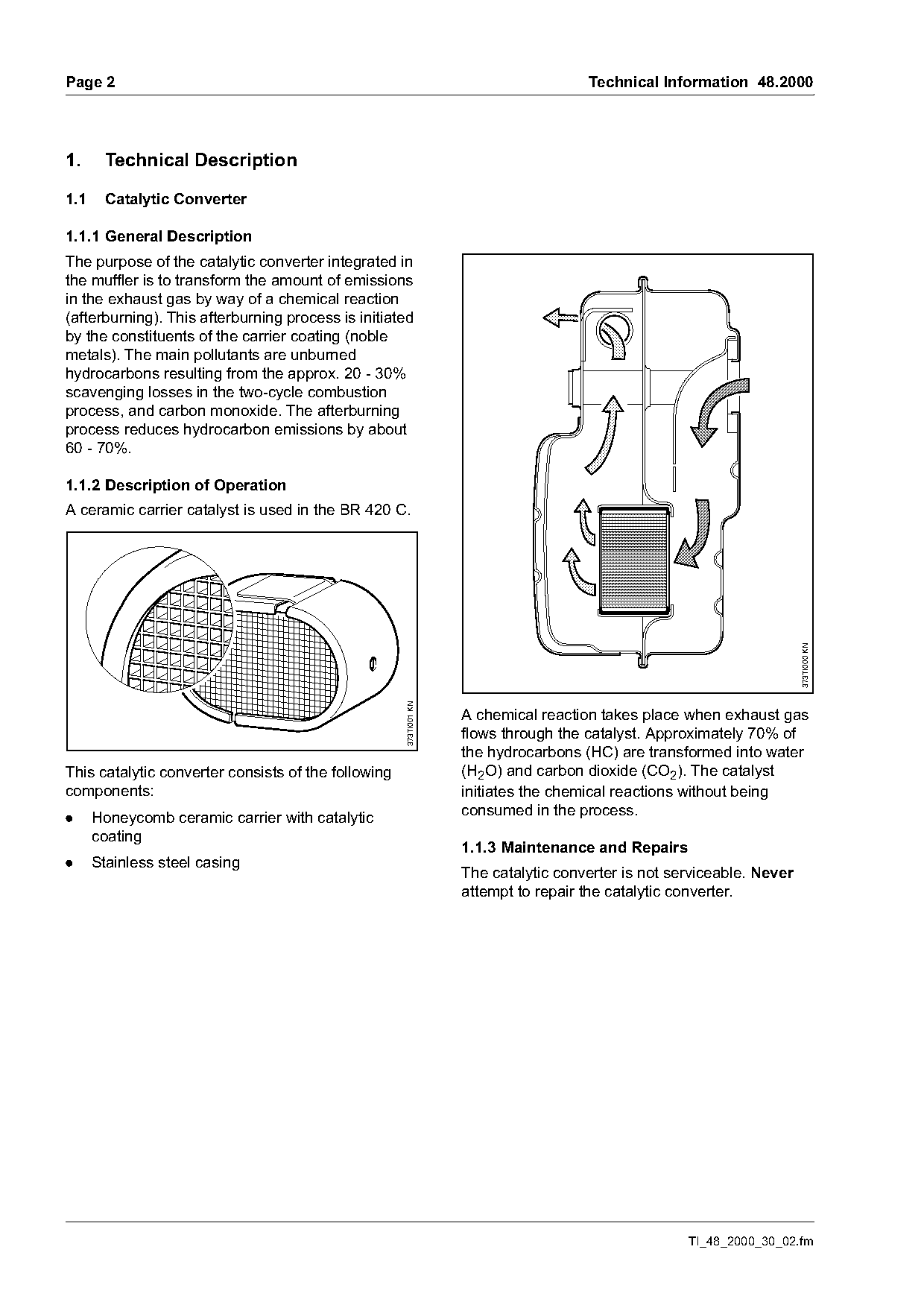
The purpose of the catalytic converter integrated in
the muffler is to transform the amount of emissions
in the exhaust gas by way of a chemical reaction
(afterburning). This afterburning process is initiated
by the constituents of the carrier coating (noble
metals). The main pollutants are unburned
hydrocarbons resulting from the approx. 20 - 30%
scavenging losses in the two-cycle combustion
process, and carbon monoxide. The afterburning
process reduces hydrocarbon emissions by about
60 - 70%.

1.1.2 Description of Operation
A ceramic carrier catalyst is used in the BR 420 C.

                                                                                                                       373TI000 KN
                                                     373TI001 KN

                                                                   A chemical reaction takes place when exhaust gas
                                                                   flows through the catalyst. Approximately 70% of
                                                                   the hydrocarbons (HC) are transformed into water
This catalytic converter consists of the following                 (H2O) and carbon dioxide (CO2). The catalyst
components:                                                        initiates the chemical reactions without being
.     Honeycomb ceramic carrier with catalytic                     consumed in the process.
      coating
                                                                   1.1.3 Maintenance and Repairs
.     Stainless steel casing
                                                                   The catalytic converter is not serviceable. Never
                                                                   attempt to repair the catalytic converter.

                                                                                                    TI_48_2000_30_02.fm
Page 3 of 7
Text of page 3 — search, copy, screen readers
Technical Information 48.2000                                                                             Page 3

1.1.4 Fuel                                              1.2     Carburetor
The two-cycle engine requires a mixture of gasoline     .     Carburetor with compensator that automatically
and engine oil.                                               keeps fuel content in mixture constant at all
                                                              times.
The quality of these constituents and the mix ratio
have a decisive influence on the function and
                                                        1.3     Air Filter
service life of the engine.
                                                        .     Paper main filter with vertical pleats.
Gasoline
                                                        .     Particularly suitable for extremely dusty
Use only mid-grade or premium gasoline with a
                                                              applications.
minimum octane rating of 89. Machines with a
catalytic converter may only be run on unleaded
                                                        1.4     Fuel Tank
gasoline.
                                                        .     Fuel tank is mounted to the backplate rather
Engine oil
                                                              than the engine – easier servicing.
Owing to the specific operating conditions in power     .     Tank vent outlet at the clean air side of the filter
tools with a catalytic converter, STIHL                       – fuel vapor from tank returned to engine for
recommends that STIHL 50:1 two-cycle engine oil               combustion – environment friendly.
or equivalent quality two cycle engine oils be used
in the fuel mix.
This STIHL engine oil reduces the build-up of
deposits in the catalyst, which is very important for
the life of the catalyst over a long period of
operation.

2.    Specifications

2.1   Engine

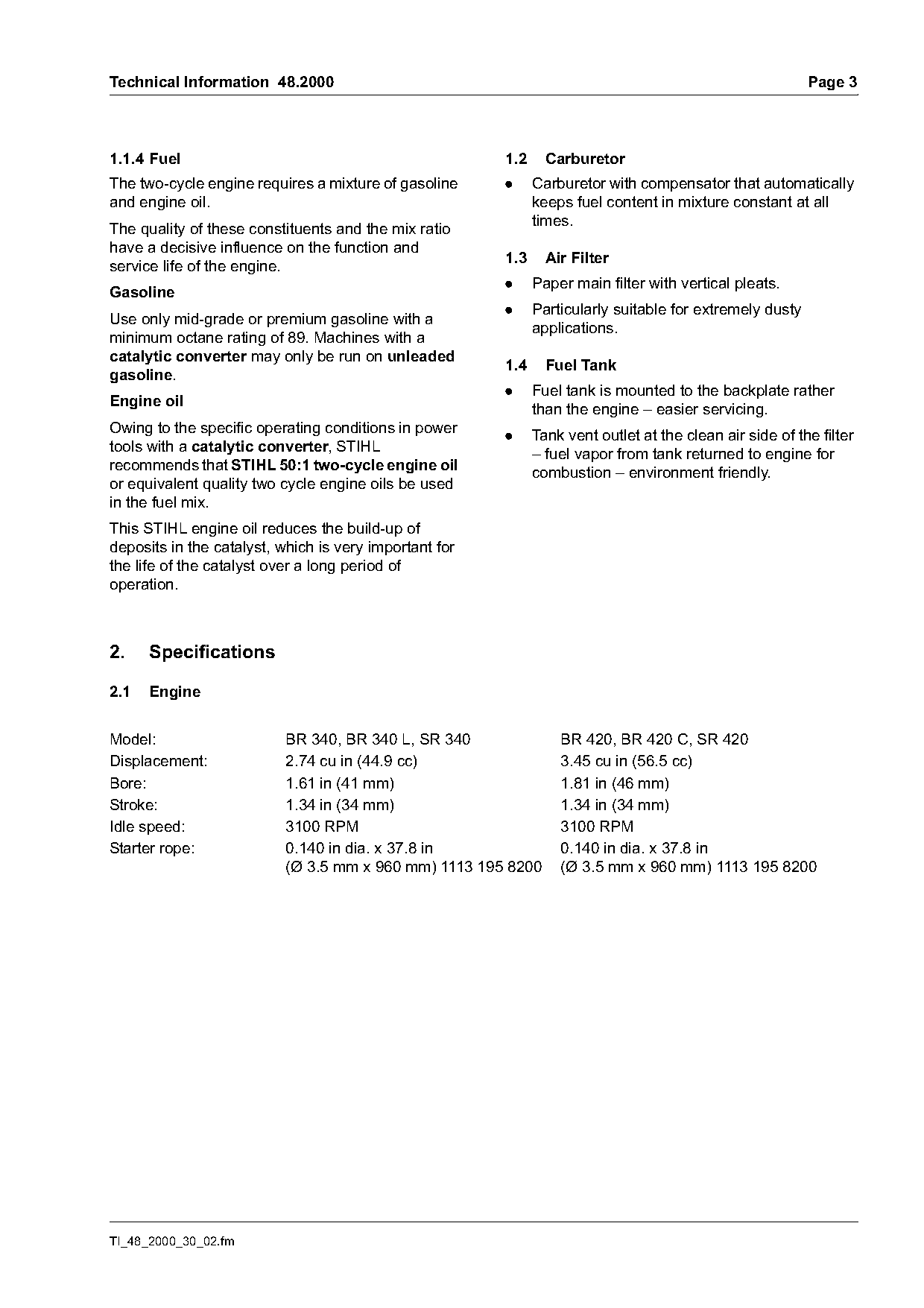
Model:                     BR 340, BR 340 L, SR 340               BR 420, BR 420 C, SR 420
Displacement:              2.74 cu in (44.9 cc)                   3.45 cu in (56.5 cc)
Bore:                      1.61 in (41 mm)                        1.81 in (46 mm)
Stroke:                    1.34 in (34 mm)                        1.34 in (34 mm)
Idle speed:                3100 RPM                               3100 RPM
Starter rope:              0.140 in dia. x 37.8 in                0.140 in dia. x 37.8 in
                           (Ø 3.5 mm x 960 mm) 1113 195 8200      (Ø 3.5 mm x 960 mm) 1113 195 8200

TI_48_2000_30_02.fm
Page 4 of 7
Text of page 4 — search, copy, screen readers
Page 4                                                                     Technical Information 48.2000

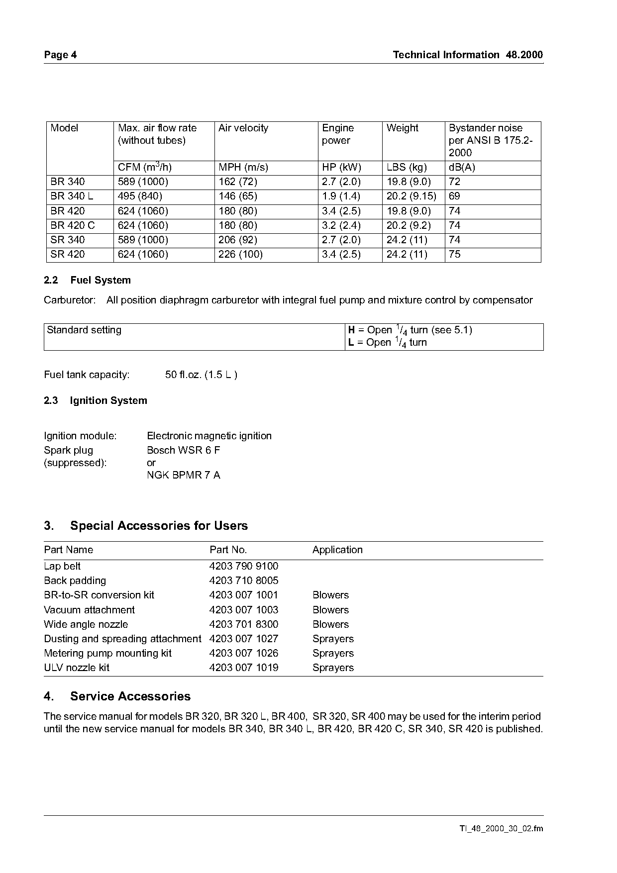
 Model             Max. air flow rate     Air velocity      Engine        Weight        Bystander noise
                   (without tubes)                          power                       per ANSI B 175.2-
                                                                                        2000
                   CFM (m3/h)             MPH (m/s)         HP (kW)       LBS (kg)      dB(A)
 BR 340            589 (1000)             162 (72)          2.7 (2.0)     19.8 (9.0)    72
 BR 340 L          495 (840)              146 (65)          1.9 (1.4)     20.2 (9.15)   69
 BR 420            624 (1060)             180 (80)          3.4 (2.5)     19.8 (9.0)    74
 BR 420 C          624 (1060)             180 (80)          3.2 (2.4)     20.2 (9.2)    74
 SR 340            589 (1000)             206 (92)          2.7 (2.0)     24.2 (11)     74
 SR 420            624 (1060)             226 (100)         3.4 (2.5)     24.2 (11)     75

2.2   Fuel System
Carburetor:   All position diaphragm carburetor with integral fuel pump and mixture control by compensator

Standard setting                                                  H = Open 1/4 turn (see 5.1)
                                                                  L = Open 1/4 turn

Fuel tank capacity:          50 fl.oz. (1.5 L )

2.3   Ignition System

Ignition module:         Electronic magnetic ignition
Spark plug               Bosch WSR 6 F
(suppressed):            or
                         NGK BPMR 7 A

3.    Special Accessories for Users
Part Name                               Part No.          Application
Lap belt                                4203 790 9100
Back padding                            4203 710 8005
BR-to-SR conversion kit                 4203 007 1001     Blowers
Vacuum attachment                       4203 007 1003     Blowers
Wide angle nozzle                       4203 701 8300     Blowers
Dusting and spreading attachment        4203 007 1027     Sprayers
Metering pump mounting kit              4203 007 1026     Sprayers
ULV nozzle kit                          4203 007 1019     Sprayers

4.    Service Accessories
The service manual for models BR 320, BR 320 L, BR 400, SR 320, SR 400 may be used for the interim period
until the new service manual for models BR 340, BR 340 L, BR 420, BR 420 C, SR 340, SR 420 is published.

                                                                                          TI_48_2000_30_02.fm
Page 5 of 7
Text of page 5 — search, copy, screen readers
Technical Information 48.2000                                                                           Page 5

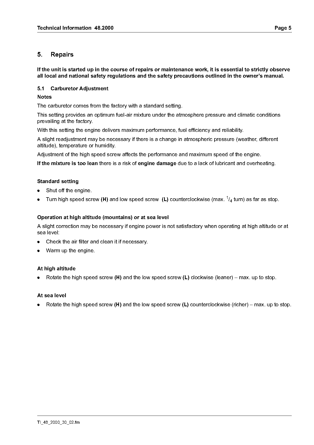
5.      Repairs

If the unit is started up in the course of repairs or maintenance work, it is essential to strictly observe
all local and national safety regulations and the safety precautions outlined in the owner’s manual.

5.1     Carburetor Adjustment
Notes
The carburetor comes from the factory with a standard setting.
This setting provides an optimum fuel-air mixture under the atmosphere pressure and climatic conditions
prevailing at the factory.
With this setting the engine delivers maximum performance, fuel efficiency and reliability.
A slight readjustment may be necessary if there is a change in atmospheric pressure (weather, different
altitude), temperature or humidity.
Adjustment of the high speed screw affects the performance and maximum speed of the engine.
If the mixture is too lean there is a risk of engine damage due to a lack of lubricant and overheating.

Standard setting
.     Shut off the engine.
.     Turn high speed screw (H) and low speed screw (L) counterclockwise (max. 1/4 turn) as far as stop.

Operation at high altitude (mountains) or at sea level
A slight correction may be necessary if engine power is not satisfactory when operating at high altitude or at
sea level:
.     Check the air filter and clean it if necessary.
.     Warm up the engine.

At high altitude
.     Rotate the high speed screw (H) and the low speed screw (L) clockwise (leaner) – max. up to stop.

At sea level
.     Rotate the high speed screw (H) and the low speed screw (L) counterclockwise (richer) – max. up to stop.

TI_48_2000_30_02.fm
Page 6 of 7
Text of page 6 — search, copy, screen readers
Page 6                                                                          Technical Information 48.2000

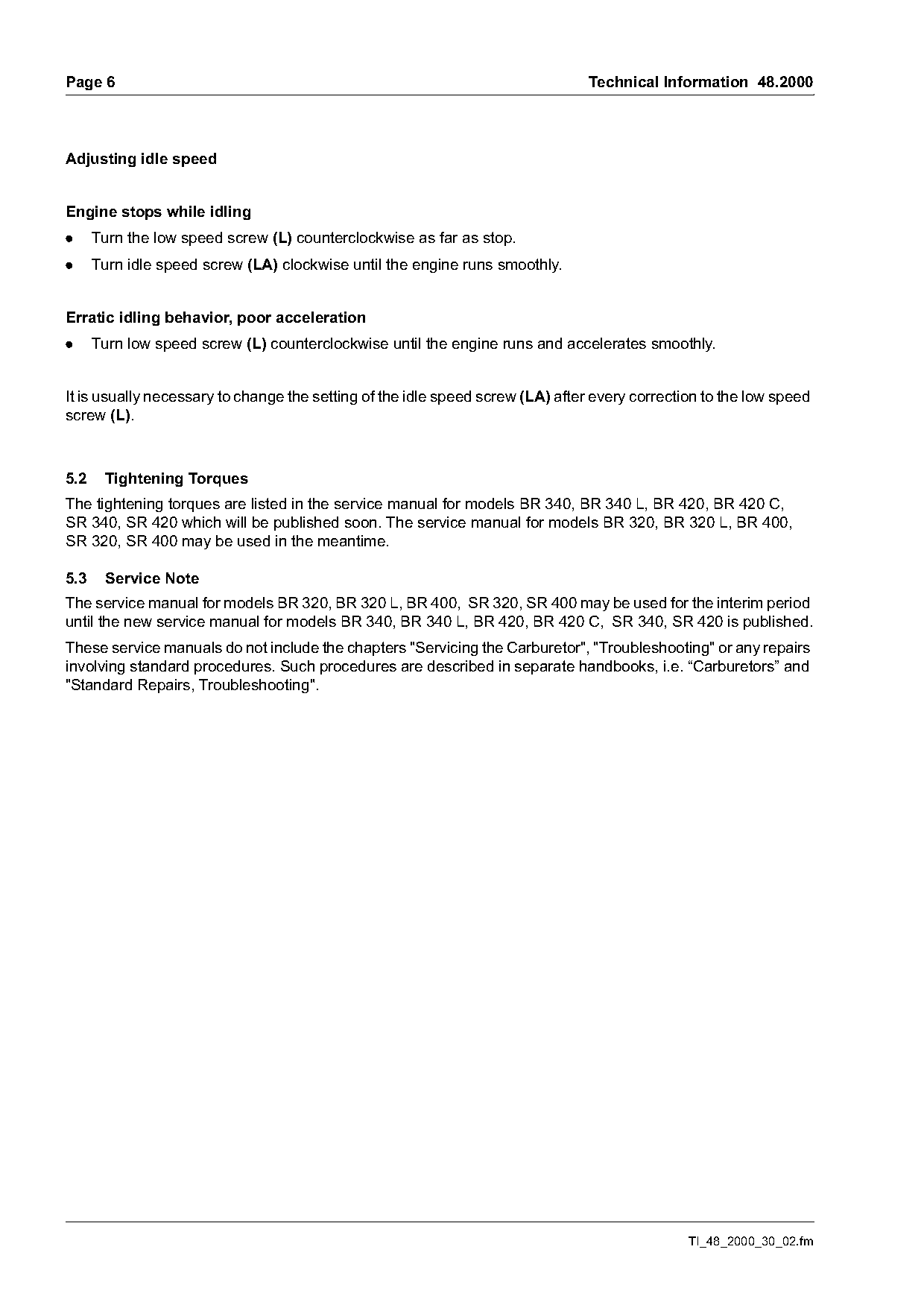
Adjusting idle speed

Engine stops while idling
.     Turn the low speed screw (L) counterclockwise as far as stop.
.     Turn idle speed screw (LA) clockwise until the engine runs smoothly.

Erratic idling behavior, poor acceleration
.     Turn low speed screw (L) counterclockwise until the engine runs and accelerates smoothly.

It is usually necessary to change the setting of the idle speed screw (LA) after every correction to the low speed
screw (L).

5.2    Tightening Torques
The tightening torques are listed in the service manual for models BR 340, BR 340 L, BR 420, BR 420 C,
SR 340, SR 420 which will be published soon. The service manual for models BR 320, BR 320 L, BR 400,
SR 320, SR 400 may be used in the meantime.

5.3    Service Note
The service manual for models BR 320, BR 320 L, BR 400, SR 320, SR 400 may be used for the interim period
until the new service manual for models BR 340, BR 340 L, BR 420, BR 420 C, SR 340, SR 420 is published.
These service manuals do not include the chapters "Servicing the Carburetor", "Troubleshooting" or any repairs
involving standard procedures. Such procedures are described in separate handbooks, i.e. “Carburetors” and
"Standard Repairs, Troubleshooting".

                                                                                               TI_48_2000_30_02.fm
Page 7 of 7
Text of page 7 — search, copy, screen readers
Technical Information 48.2000                                                                     Page 7

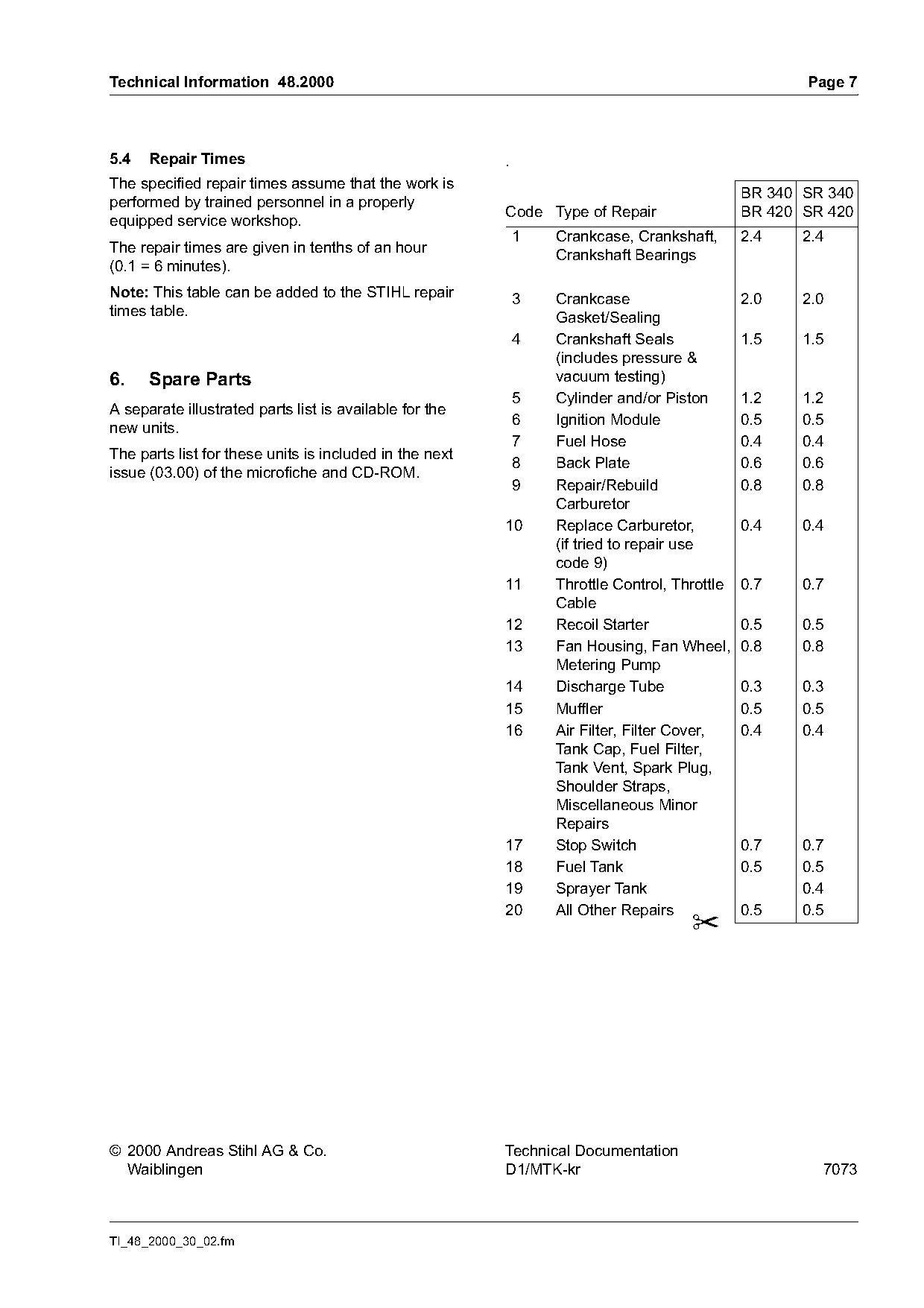
5.4   Repair Times                                       .
The specified repair times assume that the work is
                                                                                           BR 340 SR 340
performed by trained personnel in a properly
                                                         Code Type of Repair               BR 420 SR 420
equipped service workshop.
                                                             1   Crankcase, Crankshaft,    2.4    2.4
The repair times are given in tenths of an hour
                                                                 Crankshaft Bearings
(0.1 = 6 minutes).
Note: This table can be added to the STIHL repair            3   Crankcase                  2.0   2.0
times table.                                                     Gasket/Sealing
                                                             4   Crankshaft Seals           1.5   1.5
                                                                 (includes pressure &
6.    Spare Parts                                                vacuum testing)
                                                             5   Cylinder and/or Piston     1.2   1.2
A separate illustrated parts list is available for the
                                                             6   Ignition Module            0.5   0.5
new units.
                                                             7   Fuel Hose                  0.4   0.4
The parts list for these units is included in the next
                                                             8   Back Plate                 0.6   0.6
issue (03.00) of the microfiche and CD-ROM.
                                                             9   Repair/Rebuild             0.8   0.8
                                                                 Carburetor
                                                         10      Replace Carburetor,        0.4   0.4
                                                                 (if tried to repair use
                                                                 code 9)
                                                         11      Throttle Control, Throttle 0.7   0.7
                                                                 Cable
                                                         12      Recoil Starter             0.5   0.5
                                                         13      Fan Housing, Fan Wheel, 0.8      0.8
                                                                 Metering Pump
                                                         14      Discharge Tube             0.3   0.3
                                                         15      Muffler                    0.5   0.5
                                                         16      Air Filter, Filter Cover,  0.4   0.4
                                                                 Tank Cap, Fuel Filter,
                                                                 Tank Vent, Spark Plug,
                                                                 Shoulder Straps,
                                                                 Miscellaneous Minor
                                                                 Repairs
                                                         17      Stop Switch                0.7   0.7
                                                         18      Fuel Tank                  0.5   0.5
                                                         19      Sprayer Tank                     0.4
                                                         20      All Other Repairs          0.5   0.5
                                                                                    ✂

© 2000 Andreas Stihl AG & Co.                            Technical Documentation
  Waiblingen                                             D1/MTK-kr                                  7073

TI_48_2000_30_02.fm
Most of these PDFs embed fonts with a shifted character map, so the text above was recovered rather than copied — read it as a faithful but imperfect transcription, and treat the page image above each block as the authority where the two disagree — the figures exist only there, because they are vector drawings that text extraction cannot keep.