Technical Information · issue 1 of 2001
USG, HOS: Motor Arm and Handle; Guard Plate; Eye S
IssueTI 1/2001
Full text
Page 1 of 4
Text of page 1 — search, copy, screen readers
Technical Information

                                                                                             01.2001
STIHL USG and STIHL HOS Universal Grinders

Contents
1.   Motor Arm and Handle
2.   Guard Plate

3.   Debris Deflector

4.   Diamond Dressing Attachment
5.   Swivelling Tool Rest for Hedge Trimmer Blades

1.     Motor Arm and Handle
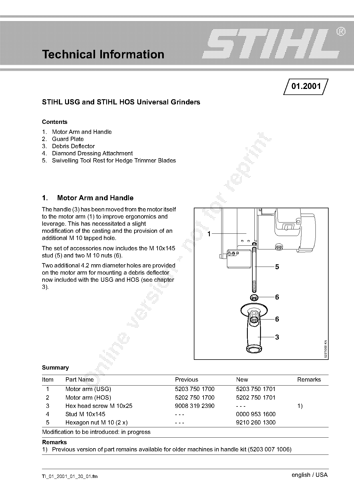
The handle (3) has been moved from the motor itself
to the motor arm (1) to improve ergonomics and
leverage. This has necessitated a slight
modification of the casting and the provision of an
                                                              1
additional M 10 tapped hole.

The set of accessories now includes the M 10x145
stud (5) and two M 10 nuts (6).
Two additional 4.2 mm diameter holes are provided                                      5
on the motor arm for mounting a debris deflector

now included with the USG and HOS (see chapter

3).
                                                                                       6


                                                                                       3
                                                                                                            523TI000 KN

Summary

Item     Part Name                                Previous               New                      Remarks
 1       Motor arm (USG)                          5203 750 1700          5203 750 1701
 2       Motor arm (HOS)                          5202 750 1700          5202 750 1701
 3       Hex head screw M 10x25                   9008 319 2390          ---                      1)
 4       Stud M 10x145                            ---                    0000 953 1600
 5       Hexagon nut M 10 (2 x)                   ---                    9210 260 1300
Modification to be introduced: in progress
Remarks
1) Previous version of part remains available for older machines in handle kit (5203 007 1006)

TI_01_2001_01_30_01.fm                                                                           english / USA
Page 2 of 4
Text of page 2 — search, copy, screen readers
Page 2                                                                 Technical Information 01.2001

2.     Guard Plate
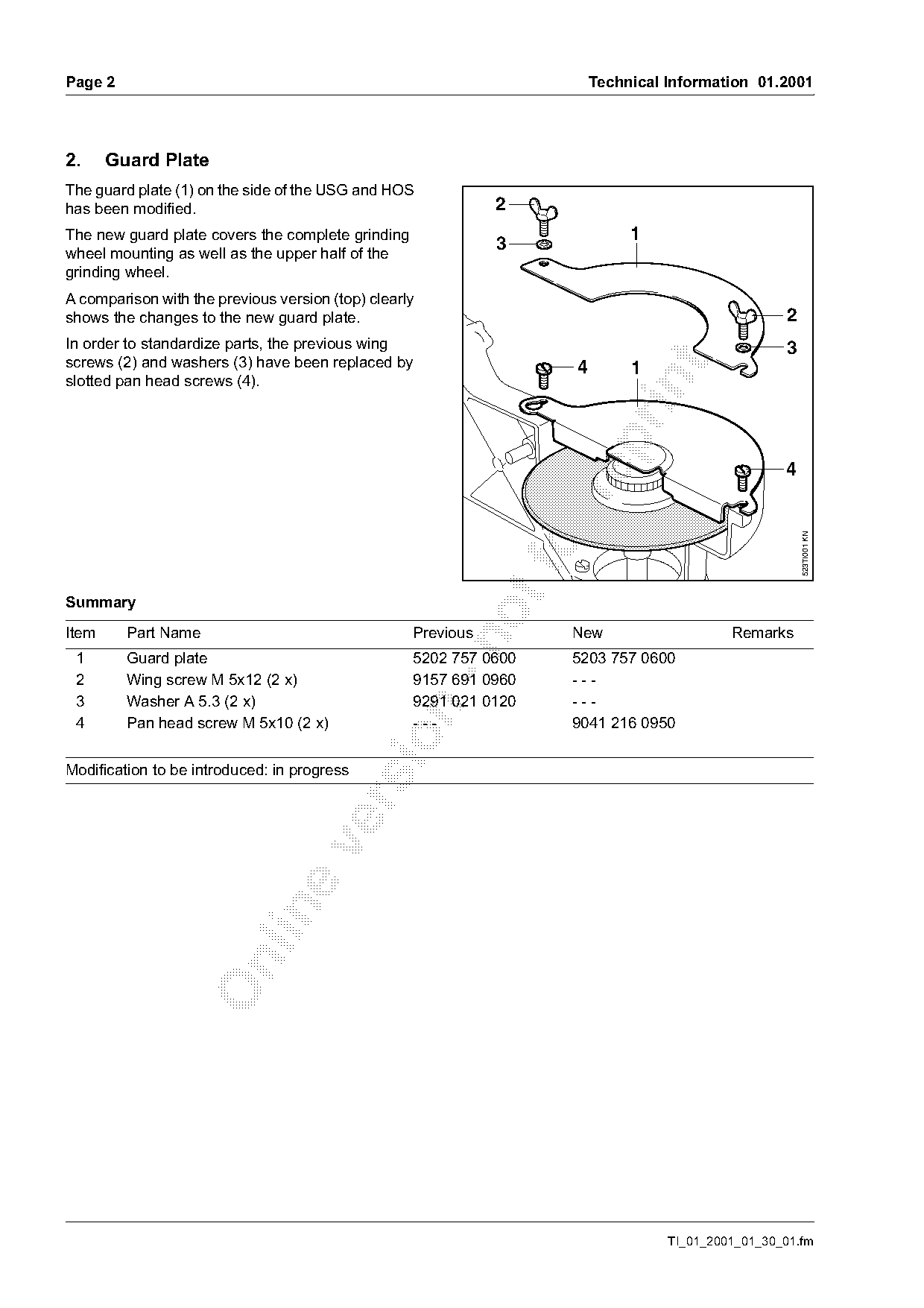
The guard plate (1) on the side of the USG and HOS
has been modified.                                            2
The new guard plate covers the complete grinding                            1
                                                              3
wheel mounting as well as the upper half of the
grinding wheel.
A comparison with the previous version (top) clearly
shows the changes to the new guard plate.                                                         2
In order to standardize parts, the previous wing                                                   3
screws (2) and washers (3) have been replaced by

                                                                   4        1
slotted pan head screws (4).


                                                                                                       523TI001 KN
Summary

Item     Part Name                                 Previous        New                    Remarks

 1       Guard plate                               5202 757 0600   5203 757 0600
 2       Wing screw M 5x12 (2 x)                   9157 691 0960   ---
 3       Washer A 5.3 (2 x)                        9291 021 0120   ---

 4       Pan head screw M 5x10 (2 x)               ---             9041 216 0950

Modification to be introduced: in progress

                                                                                 TI_01_2001_01_30_01.fm
Page 3 of 4
Text of page 3 — search, copy, screen readers
Technical Information 01.2001                                                                       Page 3

3.     Debris Deflector
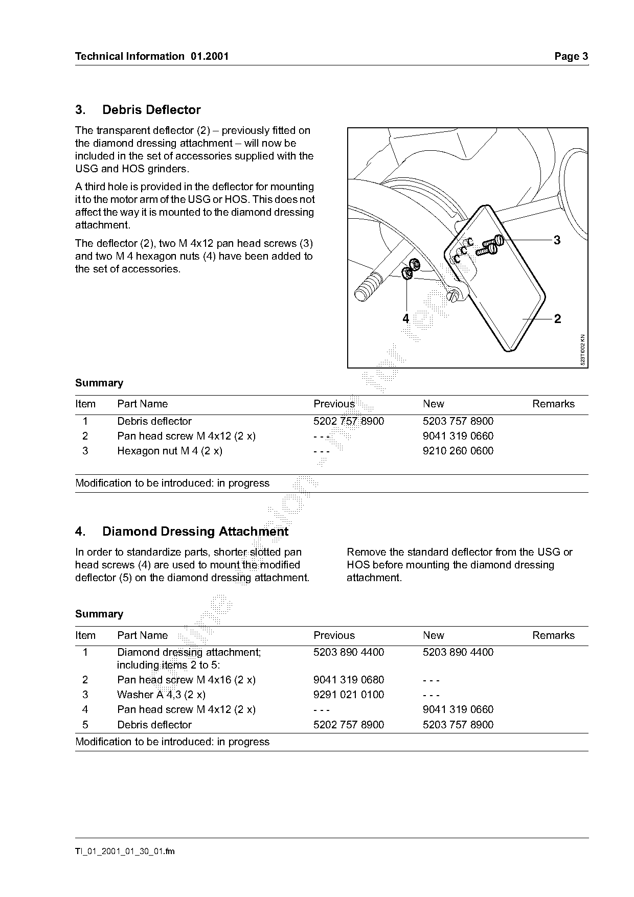
The transparent deflector (2) – previously fitted on
the diamond dressing attachment – will now be
included in the set of accessories supplied with the
USG and HOS grinders.
A third hole is provided in the deflector for mounting
it to the motor arm of the USG or HOS. This does not
affect the way it is mounted to the diamond dressing
attachment.
The deflector (2), two M 4x12 pan head screws (3)                                                   3

and two M 4 hexagon nuts (4) have been added to

the set of accessories.

                                                                      4                             2

                                                                                                           523TI002 KN
Summary
Item     Part Name                                   Previous             New                  Remarks
 1       Debris deflector                            5202 757 8900        5203 757 8900
 2       Pan head screw M 4x12 (2 x)                 ---                  9041 319 0660

 3       Hexagon nut M 4 (2 x)                       ---                  9210 260 0600

Modification to be introduced: in progress

4.     Diamond Dressing Attachment

In order to standardize parts, shorter slotted pan         Remove the standard deflector from the USG or
head screws (4) are used to mount the modified             HOS before mounting the diamond dressing
deflector (5) on the diamond dressing attachment.          attachment.

Summary

Item     Part Name                                   Previous             New                  Remarks
 1       Diamond dressing attachment;                5203 890 4400        5203 890 4400

         including items 2 to 5:
 2       Pan head screw M 4x16 (2 x)                 9041 319 0680        ---
 3       Washer A 4,3 (2 x)                          9291 021 0100        ---
 4       Pan head screw M 4x12 (2 x)                 ---                  9041 319 0660
 5       Debris deflector                            5202 757 8900        5203 757 8900
Modification to be introduced: in progress

TI_01_2001_01_30_01.fm
Page 4 of 4
Text of page 4 — search, copy, screen readers
Page 4                                                                      Technical Information 01.2001

5.     Swivelling Tool Rest
       for Hedge Trimmer Blades
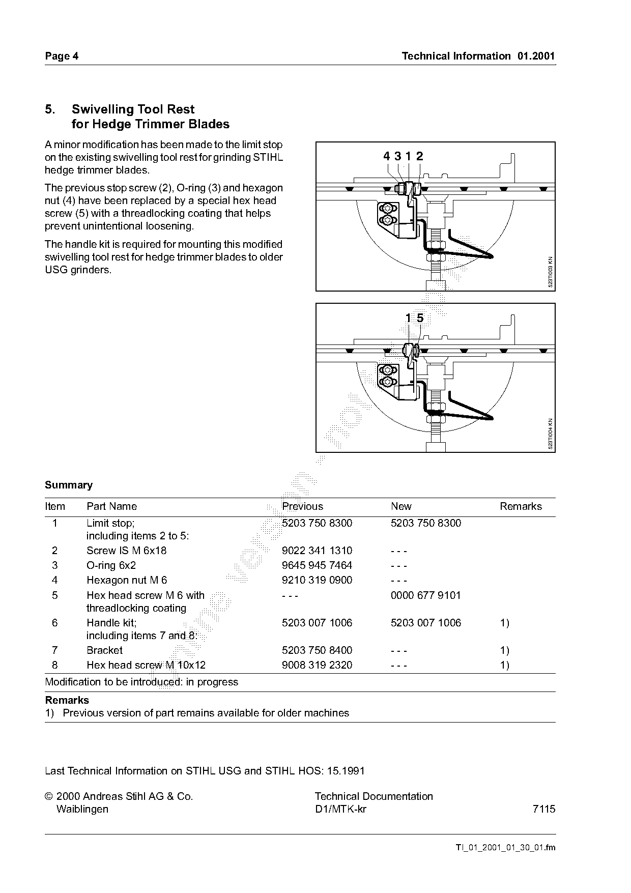
A minor modification has been made to the limit stop
on the existing swivelling tool rest for grinding STIHL                  431 2
hedge trimmer blades.
The previous stop screw (2), O-ring (3) and hexagon
nut (4) have been replaced by a special hex head
screw (5) with a threadlocking coating that helps
prevent unintentional loosening.
The handle kit is required for mounting this modified

swivelling tool rest for hedge trimmer blades to older

                                                                                                          523TI003 KN
USG grinders.


                                                                                                          523TI004 KN

Summary

Item     Part Name                                    Previous            New                  Remarks
 1       Limit stop;                                  5203 750 8300       5203 750 8300
         including items 2 to 5:

 2       Screw IS M 6x18                              9022 341 1310       ---
 3       O-ring 6x2                                   9645 945 7464       ---

 4       Hexagon nut M 6                              9210 319 0900       ---
 5       Hex head screw M 6 with                      ---                 0000 677 9101
         threadlocking coating

 6       Handle kit;                                  5203 007 1006       5203 007 1006        1)
         including items 7 and 8:
 7       Bracket                                      5203 750 8400       ---                  1)

 8       Hex head screw M 10x12                       9008 319 2320       ---                  1)
Modification to be introduced: in progress
Remarks
1) Previous version of part remains available for older machines

Last Technical Information on STIHL USG and STIHL HOS: 15.1991

© 2000 Andreas Stihl AG & Co.                               Technical Documentation
  Waiblingen                                                D1/MTK-kr                                 7115

                                                                                      TI_01_2001_01_30_01.fm
Most of these PDFs embed fonts with a shifted character map, so the text above was recovered rather than copied — read it as a faithful but imperfect transcription, and treat the page image above each block as the authority where the two disagree — the figures exist only there, because they are vector drawings that text extraction cannot keep.