Technical Information · issue 4 of 2001
Carburetor; Fan Housing; Throttle Cable / Throttle
Model BG 55, 65 Blowers and SH 55 Vacuum Shredder – Series 4229
IssueTI 4/2001
Part changes (1)
| Was | Becomes | What the bulletin says |
|---|---|---|
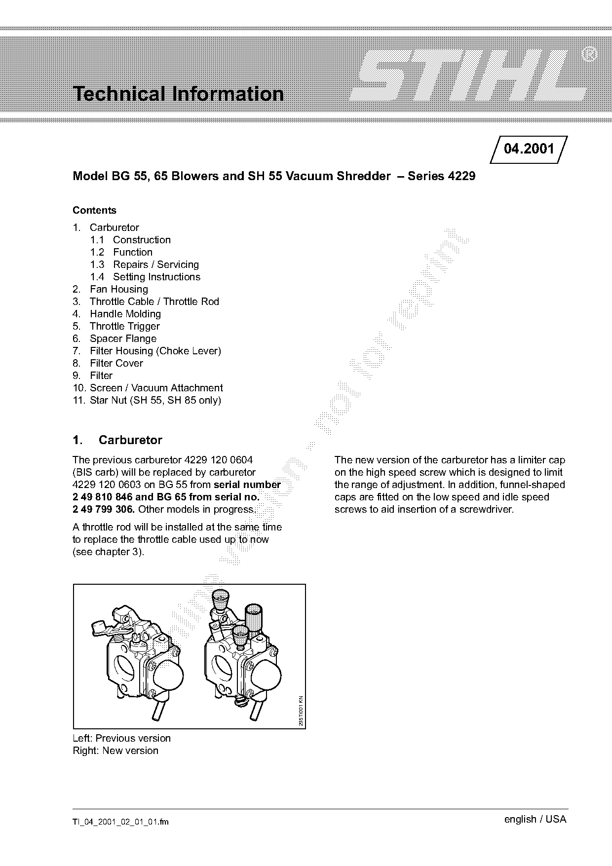
| 4229 120 0604 | 4229 120 0603 | Carburetor The previous carburetor 4229 120 0604 The new version of the carburetor has a limiter cap (BIS carb) will be replaced by carburetor on the high speed screw which is designed to limit 4229 120 0603 on BG 55 from serial number the range of adjustment. |
Full text
Page 1 of 7
Text of page 1 — search, copy, screen readers
Technical Information

                                                                                                       04.2001
Model BG 55, 65 Blowers and SH 55 Vacuum Shredder – Series 4229

Contents
1. Carburetor
    1.1 Construction

    1.2 Function

    1.3 Repairs / Servicing
    1.4 Setting Instructions
2. Fan Housing

3. Throttle Cable / Throttle Rod
4. Handle Molding
5. Throttle Trigger

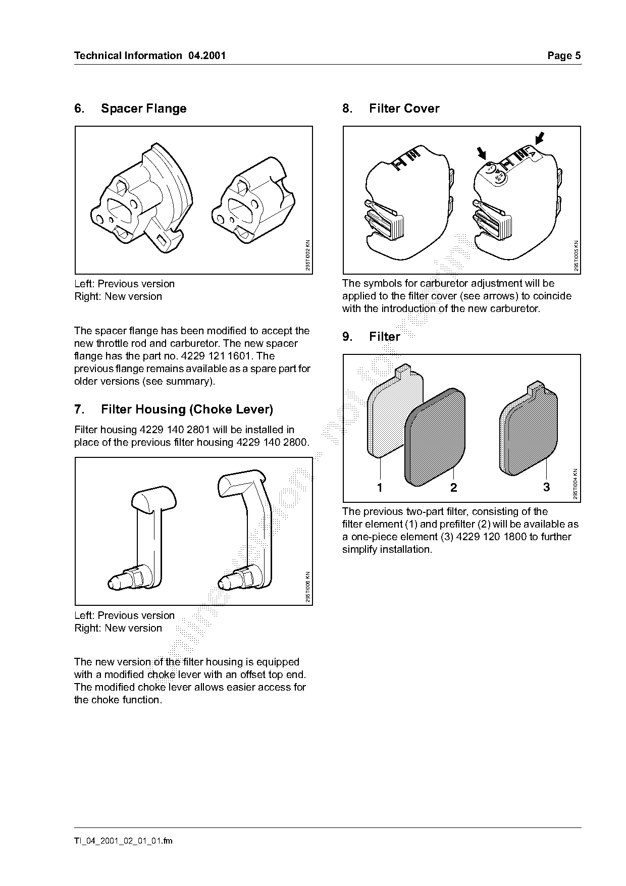
6. Spacer Flange
7. Filter Housing (Choke Lever)
8. Filter Cover
9. Filter
10. Screen / Vacuum Attachment
11. Star Nut (SH 55, SH 85 only)

1.    Carburetor
The previous carburetor 4229 120 0604                             The new version of the carburetor has a limiter cap

(BIS carb) will be replaced by carburetor                         on the high speed screw which is designed to limit
4229 120 0603 on BG 55 from serial number                         the range of adjustment. In addition, funnel-shaped

2 49 810 846 and BG 65 from serial no.                            caps are fitted on the low speed and idle speed
2 49 799 306. Other models in progress.                           screws to aid insertion of a screwdriver.
A throttle rod will be installed at the same time

to replace the throttle cable used up to now
(see chapter 3).

                                                    295TI001 KN

Left: Previous version
Right: New version

TI_04_2001_02_01_01.fm                                                                                 english / USA
Page 2 of 7
Text of page 2 — search, copy, screen readers
Page 2                                                                                      Technical Information 04.2001

1.1    Construction                                                   1.3     Repairs / Servicing

       4                                       1
                                               2
                                                   3

                                                                                                                                295TI014 KN
                                                        295TI011 KN

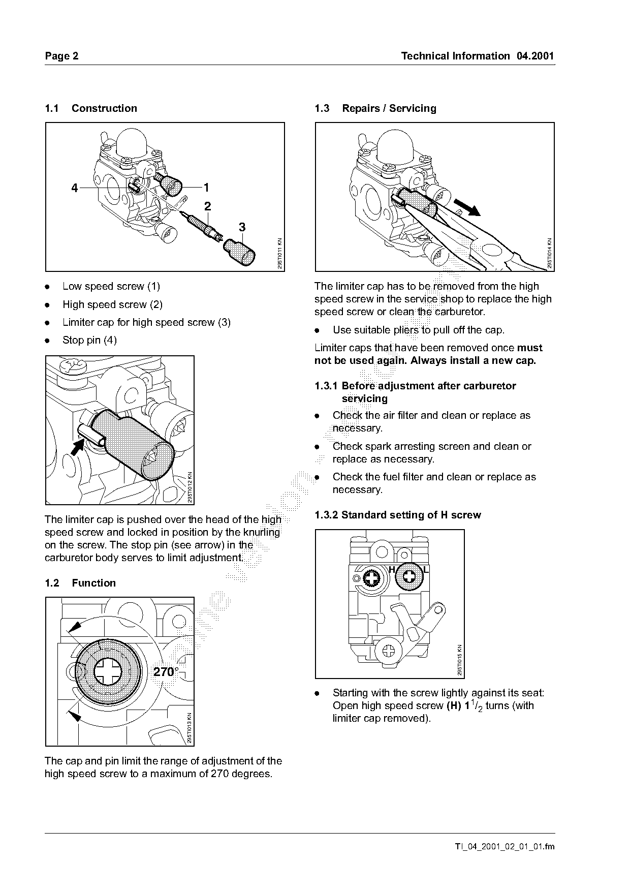
.     Low speed screw (1)                                             The limiter cap has to be removed from the high
                                                                      speed screw in the service shop to replace the high

.     High speed screw (2)
                                                                      speed screw or clean the carburetor.
.     Limiter cap for high speed screw (3)
                                                                      .     Use suitable pliers to pull off the cap.

.     Stop pin (4)
                                                                      Limiter caps that have been removed once must
                                                                      not be used again. Always install a new cap.
                                                                      1.3.1 Before adjustment after carburetor
                                                                            servicing
                                                                      .     Check the air filter and clean or replace as
                                                                            necessary.

                                                                      .     Check spark arresting screen and clean or
                                                                            replace as necessary.
                                                                      .     Check the fuel filter and clean or replace as
                                 295TI012 KN

                                                                            necessary.

The limiter cap is pushed over the head of the high                   1.3.2 Standard setting of H screw
speed screw and locked in position by the knurling
on the screw. The stop pin (see arrow) in the

carburetor body serves to limit adjustment.
                                                                                        H       L

1.2    Function

                                                                                                        295TI015 KN

                         270°
                                                                      .     Starting with the screw lightly against its seat:
                                                                            Open high speed screw (H) 11/2 turns (with
                                                                            limiter cap removed).
                                295TI013 KN

The cap and pin limit the range of adjustment of the
high speed screw to a maximum of 270 degrees.

                                                                                                        TI_04_2001_02_01_01.fm
Page 3 of 7
Text of page 3 — search, copy, screen readers
Technical Information 04.2001                                                                          Page 3

1.3.3 Installing the limiter cap                          1.4   Setting Instructions
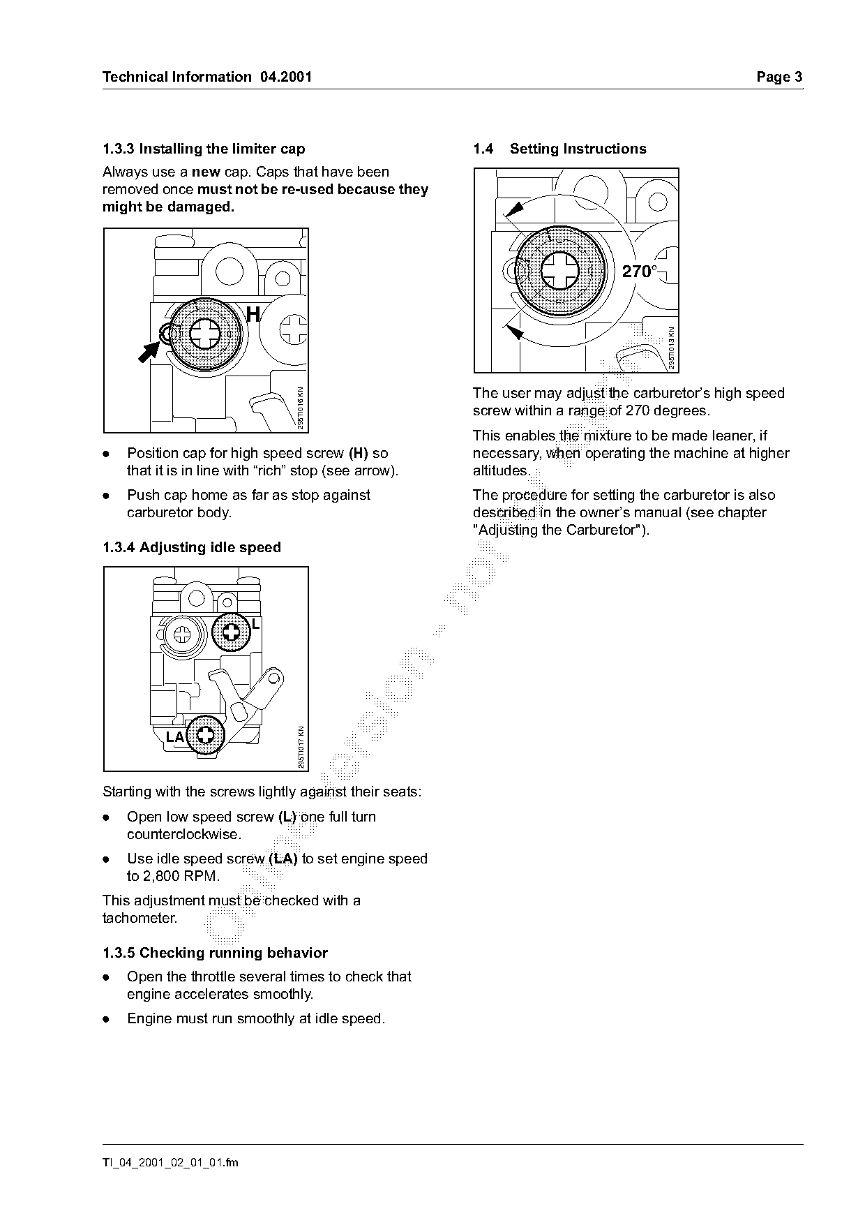
Always use a new cap. Caps that have been
removed once must not be re-used because they
might be damaged.

                                                                                 270°


                                                                                         295TI013 KN
                                                          The user may adjust the carburetor’s high speed
                                  295TI016 KN

                                                          screw within a range of 270 degrees.

                                                          This enables the mixture to be made leaner, if
.   Position cap for high speed screw (H) so              necessary, when operating the machine at higher

    that it is in line with “rich” stop (see arrow).      altitudes.
.   Push cap home as far as stop against                  The procedure for setting the carburetor is also
    carburetor body.                                        fo
                                                          described in the owner’s manual (see chapter
                                                          "Adjusting the Carburetor").
1.3.4 Adjusting idle speed

                                   295TI017 KN


Starting with the screws lightly against their seats:

.   Open low speed screw (L) one full turn
    counterclockwise.

.   Use idle speed screw (LA) to set engine speed
    to 2,800 RPM.
This adjustment must be checked with a

tachometer.

1.3.5 Checking running behavior
.   Open the throttle several times to check that
    engine accelerates smoothly.
.   Engine must run smoothly at idle speed.

TI_04_2001_02_01_01.fm
Page 4 of 7
Text of page 4 — search, copy, screen readers
Page 4                                                                                  Technical Information 04.2001

2.   Fan Housing                                                  4.   Handle Molding


                                                    295TI003 KN

                                                                                                                       295TI009 KN
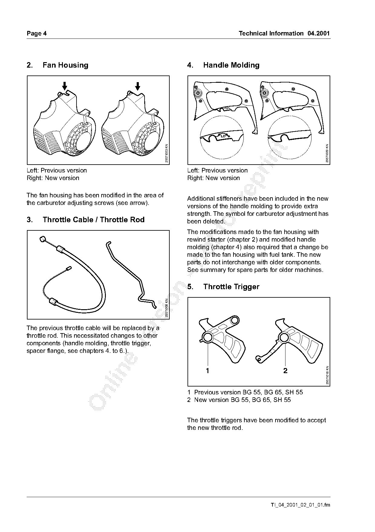
Left: Previous version                                            Left: Previous version
Right: New version                                                Right: New version

The fan housing has been modified in the area of
                                                                  Additional stiffeners have been included in the new

the carburetor adjusting screws (see arrow).
                                                                  versions of the handle molding to provide extra
                                                                  strength. The symbol for carburetor adjustment has
3.   Throttle Cable / Throttle Rod                                       fo
                                                                  been deleted.
                                                                  The modifications made to the fan housing with
                                                                  rewind starter (chapter 2) and modified handle
                                                                  molding (chapter 4) also required that a change be
                                                                  made to the fan housing with fuel tank. The new

                                                                  parts do not interchange with older components.
                                                                  See summary for spare parts for older machines.

                                                                  5.   Throttle Trigger
                                            sio     295TI008 KN

The previous throttle cable will be replaced by a
throttle rod. This necessitated changes to other
components (handle molding, throttle trigger,

spacer flange, see chapters 4. to 6.).
                                                                                                                       295TI018 KN

                                                                        1                             2

                                                                  1 Previous version BG 55, BG 65, SH 55

                                                                  2 New version BG 55, BG 65, SH 55

                                                                  The throttle triggers have been modified to accept
                                                                  the new throttle rod.

                                                                                                  TI_04_2001_02_01_01.fm
Page 5 of 7
Text of page 5 — search, copy, screen readers
Technical Information 04.2001                                                                                          Page 5

6.    Spacer Flange                                              8.    Filter Cover

                                                                                                                  LA
                                                                                                   1

                                                                                                           H /4
                                                                                                            3
                                                   295TI002 KN

                                                                                                                            295TI005 KN
Left: Previous version                                           The symbols for carburetor adjustment will be
Right: New version                                               applied to the filter cover (see arrows) to coincide

                                                                 with the introduction of the new carburetor.

The spacer flange has been modified to accept the
                                                                 9.    Filter

new throttle rod and carburetor. The new spacer
flange has the part no. 4229 121 1601. The
previous flange remains available as a spare part for
older versions (see summary).
7.    Filter Housing (Choke Lever)
Filter housing 4229 140 2801 will be installed in

place of the previous filter housing 4229 140 2800.

                                                                                                                           295TI004 KN

                                                                         1                 2                           3

                                                                 The previous two-part filter, consisting of the
                                                                 filter element (1) and prefilter (2) will be available as
                                                                 a one-piece element (3) 4229 120 1800 to further

                                                                 simplify installation.

                                                   295TI006 KN

Left: Previous version

Right: New version

The new version of the filter housing is equipped
with a modified choke lever with an offset top end.
The modified choke lever allows easier access for
the choke function.

TI_04_2001_02_01_01.fm
Page 6 of 7
Text of page 6 — search, copy, screen readers
Page 6                                                                  Technical Information 04.2001

10. Screen / Vacuum Attachment

                                                295TI010 KN

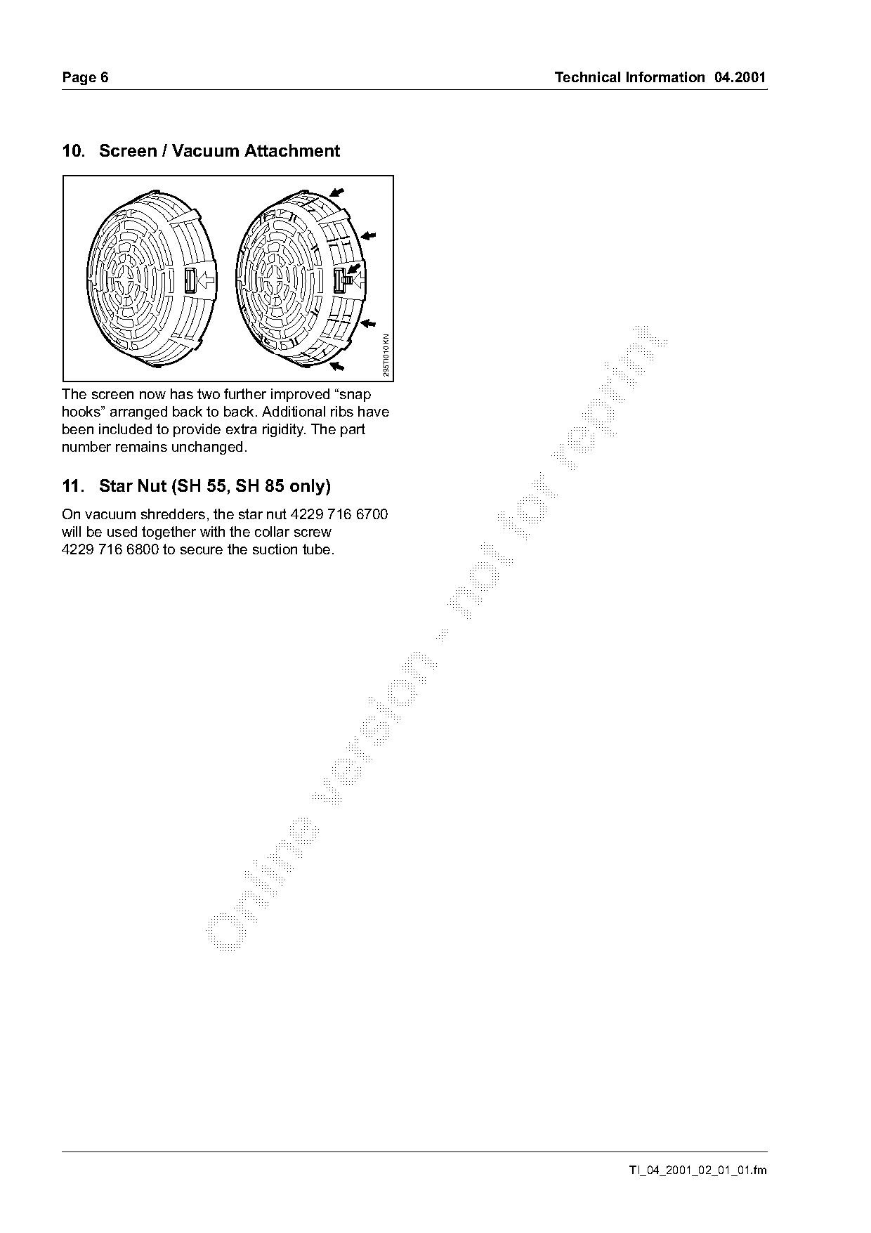
The screen now has two further improved “snap
hooks” arranged back to back. Additional ribs have

been included to provide extra rigidity. The part
number remains unchanged.

11. Star Nut (SH 55, SH 85 only)
On vacuum shredders, the star nut 4229 716 6700
will be used together with the collar screw
4229 716 6800 to secure the suction tube.

                                                                                  TI_04_2001_02_01_01.fm
Page 7 of 7
Text of page 7 — search, copy, screen readers
Technical Information 04.2001                                                                       Page 7

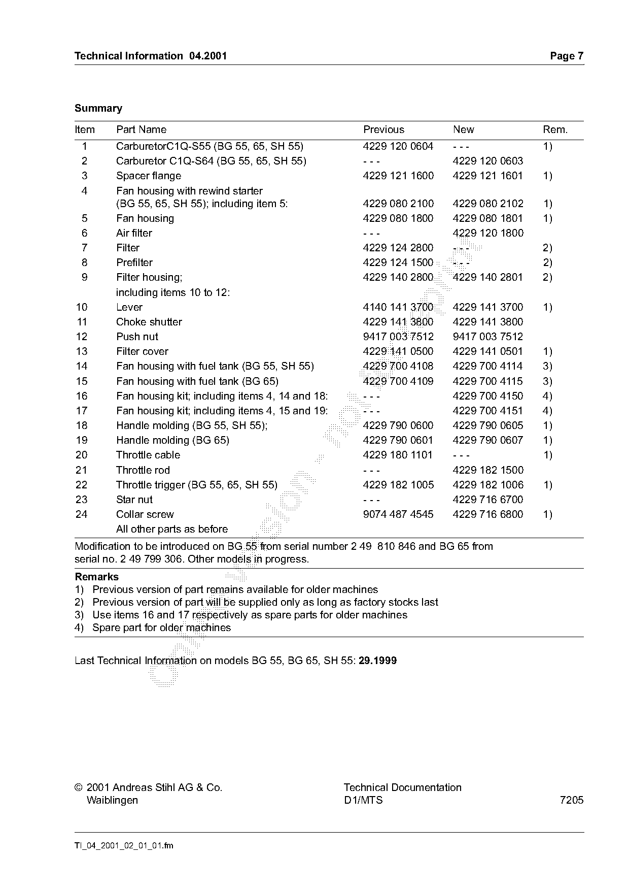
Summary

Item     Part Name                                             Previous            New             Rem.
 1       CarburetorC1Q-S55 (BG 55, 65, SH 55)                  4229 120 0604       ---             1)
 2       Carburetor C1Q-S64 (BG 55, 65, SH 55)                 ---                 4229 120 0603
 3       Spacer flange                                         4229 121 1600       4229 121 1601   1)
 4       Fan housing with rewind starter
         (BG 55, 65, SH 55); including item 5:                 4229 080 2100       4229 080 2102   1)
 5       Fan housing                                           4229 080 1800       4229 080 1801   1)
 6       Air filter                                            ---                 4229 120 1800
 7       Filter                                                4229 124 2800       ---             2)

 8       Prefilter                                             4229 124 1500       ---             2)
 9       Filter housing;                                       4229 140 2800       4229 140 2801   2)
         including items 10 to 12:

10       Lever                                                 4140 141 3700       4229 141 3700   1)
11       Choke shutter                                         4229 141 3800       4229 141 3800
12       Push nut                                              9417 003 7512       9417 003 7512

13       Filter cover                                          4229 141 0500       4229 141 0501   1)
14       Fan housing with fuel tank (BG 55, SH 55)             4229 700 4108       4229 700 4114   3)
15       Fan housing with fuel tank (BG 65)
                                                            fo 4229 700 4109       4229 700 4115   3)
16       Fan housing kit; including items 4, 14 and 18:        ---                 4229 700 4150   4)
17       Fan housing kit; including items 4, 15 and 19:        ---                 4229 700 4151   4)
18       Handle molding (BG 55, SH 55);                        4229 790 0600       4229 790 0605   1)

19       Handle molding (BG 65)                                4229 790 0601       4229 790 0607   1)
20       Throttle cable                                        4229 180 1101       ---             1)
21       Throttle rod                                          ---                 4229 182 1500

22       Throttle trigger (BG 55, 65, SH 55)                   4229 182 1005       4229 182 1006   1)
23       Star nut                                              ---                 4229 716 6700

24       Collar screw                                          9074 487 4545       4229 716 6800   1)
         All other parts as before
Modification to be introduced on BG 55 from serial number 2 49 810 846 and BG 65 from

serial no. 2 49 799 306. Other models in progress.
Remarks

1) Previous version of part remains available for older machines
2) Previous version of part will be supplied only as long as factory stocks last
3) Use items 16 and 17 respectively as spare parts for older machines

4) Spare part for older machines

Last Technical Information on models BG 55, BG 65, SH 55: 29.1999

© 2001 Andreas Stihl AG & Co.                              Technical Documentation
  Waiblingen                                               D1/MTS                                       7205

TI_04_2001_02_01_01.fm
Most of these PDFs embed fonts with a shifted character map, so the text above was recovered rather than copied — read it as a faithful but imperfect transcription, and treat the page image above each block as the authority where the two disagree — the figures exist only there, because they are vector drawings that text extraction cannot keep.