Technical Information · issue 8 of 2001
New Model FS 83 RT Brushcutter
IssueTI 8/2001
Full text
Page 1 of 8
Text of page 1 — search, copy, screen readers
Technical Information

                                                                       08.2001
New Model FS 83 RT Brushcutter - Series 4141
California Only

Contents
1.   Technical Description

2.   Specifications
3.   Tools
4.   Accessories
5.   Service Accessories

6.   Repairs
7.   Spare Parts

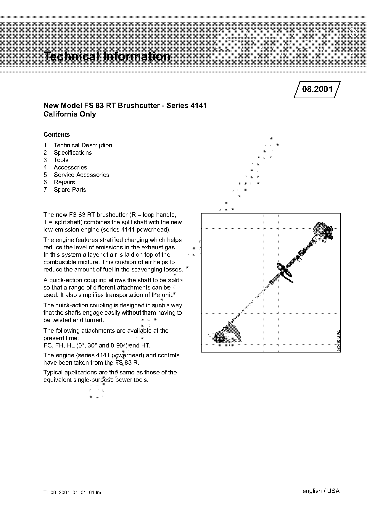
The new FS 83 RT brushcutter (R = loop handle,
T = split shaft) combines the split shaft with the new
low-emission engine (series 4141 powerhead).
The engine features stratified charging which helps
reduce the level of emissions in the exhaust gas.
In this system a layer of air is laid on top of the

combustible mixture. This cushion of air helps to
reduce the amount of fuel in the scavenging losses.
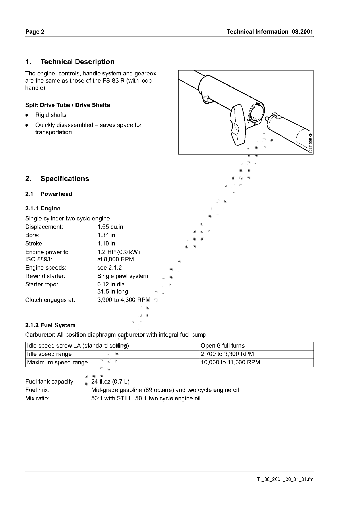
A quick-action coupling allows the shaft to be split

so that a range of different attachments can be

used. It also simplifies transportation of the unit.
The quick-action coupling is designed in such a way
that the shafts engage easily without them having to

be twisted and turned.
The following attachments are available at the

present time:
FC, FH, HL (0°, 30° and 0-90°) and HT.
The engine (series 4141 powerhead) and controls

have been taken from the FS 83 R.
Typical applications are the same as those of the
equivalent single-purpose power tools.

TI_08_2001_01_01_01.fm                                                 english / USA
Page 2 of 8
Text of page 2 — search, copy, screen readers
Page 2                                                                     Technical Information 08.2001

1.     Technical Description
The engine, controls, handle system and gearbox
are the same as those of the FS 83 R (with loop
handle).

Split Drive Tube / Drive Shafts
.     Rigid shafts
.     Quickly disassembled – saves space for
      transportation

                                                                                                         393TI005 KN
2.     Specifications

2.1    Powerhead

2.1.1 Engine
Single cylinder two cycle engine
Displacement:               1.55 cu.in
Bore:                       1.34 in
Stroke:                     1.10 in

Engine power to             1.2 HP (0.9 kW)
ISO 8893:                   at 8,000 RPM
Engine speeds:              see 2.1.2

Rewind starter:             Single pawl system
Starter rope:               0.12 in dia.

                            31.5 in long
Clutch engages at:          3,900 to 4,300 RPM

2.1.2 Fuel System

Carburetor: All position diaphragm carburetor with integral fuel pump
Idle speed screw LA (standard setting)                            Open 6 full turns

Idle speed range                                                  2,700 to 3,300 RPM
Maximum speed range                                               10,000 to 11,000 RPM

Fuel tank capacity:      24 fl.oz (0.7 L)
Fuel mix:                Mid-grade gasoline (89 octane) and two cycle engine oil
Mix ratio:               50:1 with STIHL 50:1 two cycle engine oil

                                                                                     TI_08_2001_30_01_01.fm
Page 3 of 8
Text of page 3 — search, copy, screen readers
Technical Information 08.2001                                                   Page 3

2.1.3 Ignition System
Ignition module:         with speed governor
Spark plug               NGK CMR 7 A
(suppressed):            0000 400 7007
Electrode gap:           0.020-0.024 in
Spark plug thread:       M10x1.0
                         0.37 in long

2.2   Weight
without cutting tool and deflector:        11.9 lbs

3.    Tools

3.1   FS Cutting Tools
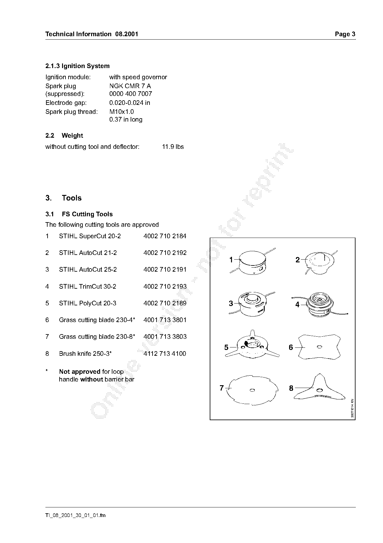
The following cutting tools are approved
1     STIHL SuperCut 20-2             4002 710 2184
2     STIHL AutoCut 21-2              4002 710 2192
                                                               1            2

3     STIHL AutoCut 25-2              4002 710 2191

4     STIHL TrimCut 30-2              4002 710 2193

5     STIHL PolyCut 20-3              4002 710 2189            3            4

6     Grass cutting blade 230-4*      4001 713 3801

7     Grass cutting blade 230-8*      4001 713 3803
                                                           5            6

8     Brush knife 250-3*              4112 713 4100

*     Not approved for loop

      handle without barrier bar
                                                       7                8

                                                                                    380TI014 KN

TI_08_2001_30_01_01.fm
Page 4 of 8
Text of page 4 — search, copy, screen readers
Page 4                                                               Technical Information 08.2001

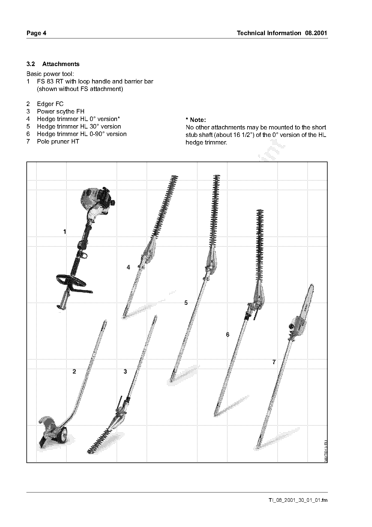
3.2    Attachments
Basic power tool:
1 FS 83 RT with loop handle and barrier bar
   (shown without FS attachment)

2     Edger FC
3     Power scythe FH
4     Hedge trimmer HL 0° version*                * Note:
5     Hedge trimmer HL 30° version                No other attachments may be mounted to the short
6     Hedge trimmer HL 0-90° version              stub shaft (about 16 1/2”) of the 0° version of the HL
7     Pole pruner HT                              hedge trimmer.

                                                                                 TI_08_2001_30_01_01.fm
Page 5 of 8
Text of page 5 — search, copy, screen readers
Technical Information 08.2001                                                                     Page 5

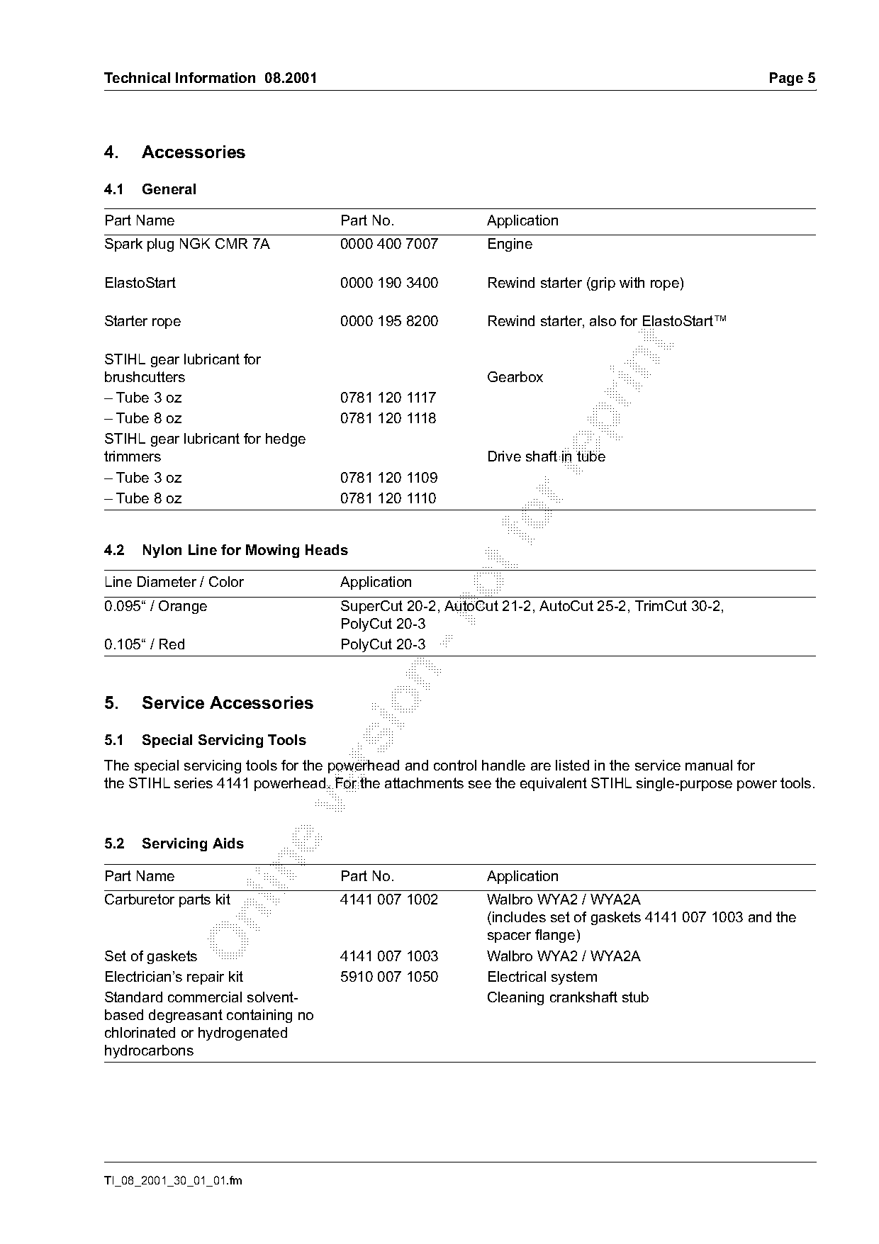
4.    Accessories

4.1   General

Part Name                         Part No.              Application
Spark plug NGK CMR 7A             0000 400 7007         Engine

ElastoStart                       0000 190 3400         Rewind starter (grip with rope)

Starter rope                      0000 195 8200         Rewind starter, also for ElastoStart™

STIHL gear lubricant for

brushcutters                                            Gearbox
– Tube 3 oz                       0781 120 1117
– Tube 8 oz                       0781 120 1118

STIHL gear lubricant for hedge
trimmers                                                Drive shaft in tube

– Tube 3 oz                       0781 120 1109
– Tube 8 oz                       0781 120 1110

4.2   Nylon Line for Mowing Heads
Line Diameter / Color             Application
0.095“ / Orange                   SuperCut 20-2, AutoCut 21-2, AutoCut 25-2, TrimCut 30-2,

                                  PolyCut 20-3
0.105“ / Red                      PolyCut 20-3

5.    Service Accessories

5.1   Special Servicing Tools

The special servicing tools for the powerhead and control handle are listed in the service manual for
the STIHL series 4141 powerhead. For the attachments see the equivalent STIHL single-purpose power tools.

5.2   Servicing Aids

Part Name                         Part No.              Application
Carburetor parts kit              4141 007 1002         Walbro WYA2 / WYA2A

                                                        (includes set of gaskets 4141 007 1003 and the
                                                        spacer flange)
Set of gaskets                    4141 007 1003         Walbro WYA2 / WYA2A
Electrician’s repair kit          5910 007 1050         Electrical system
Standard commercial solvent-                            Cleaning crankshaft stub
based degreasant containing no
chlorinated or hydrogenated
hydrocarbons

TI_08_2001_30_01_01.fm
Page 6 of 8
Text of page 6 — search, copy, screen readers
Page 6                                                                       Technical Information 08.2001

6.      Repairs
If the unit is started up in the course of repairs, it is essential to strictly observe all country-specific
safety regulations and the safety precautions outlined in the owner’s manual.

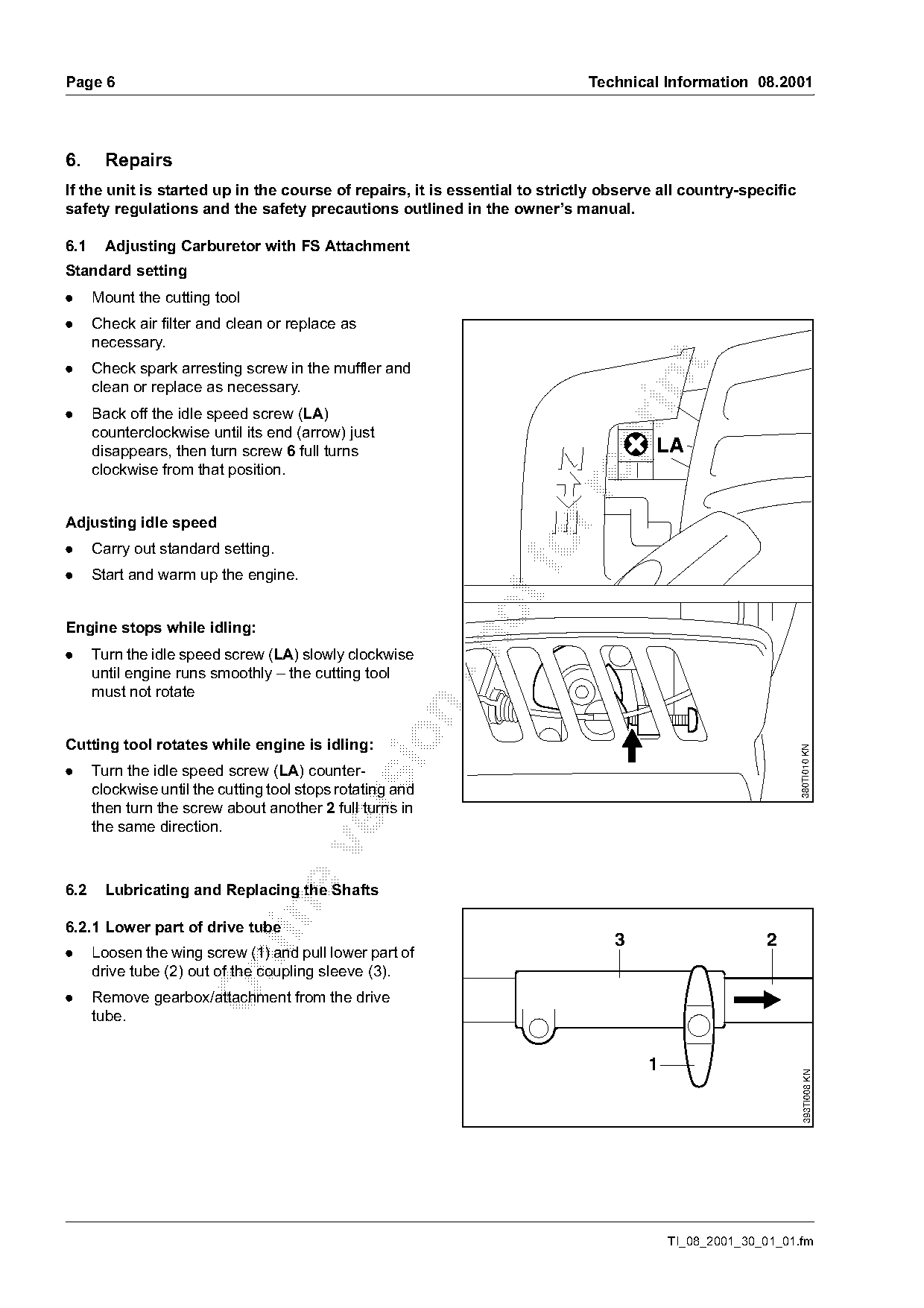
6.1     Adjusting Carburetor with FS Attachment
Standard setting
.     Mount the cutting tool
.     Check air filter and clean or replace as
      necessary.
.

      Check spark arresting screw in the muffler and

      clean or replace as necessary.
.     Back off the idle speed screw (LA)
      counterclockwise until its end (arrow) just

      disappears, then turn screw 6 full turns                                         LA
      clockwise from that position.

Adjusting idle speed
.
.
      Carry out standard setting.
      Start and warm up the engine.

Engine stops while idling:

.     Turn the idle speed screw (LA) slowly clockwise
      until engine runs smoothly – the cutting tool
      must not rotate

Cutting tool rotates while engine is idling:

                                                                                                               380TI010 KN
.     Turn the idle speed screw (LA) counter-
      clockwise until the cutting tool stops rotating and

      then turn the screw about another 2 full turns in
      the same direction.

6.2     Lubricating and Replacing the Shafts

6.2.1 Lower part of drive tube
                                                                                 3                      2
.     Loosen the wing screw (1) and pull lower part of

      drive tube (2) out of the coupling sleeve (3).
.     Remove gearbox/attachment from the drive
      tube.

                                                                                      1
                                                                                                                 393TI008 KN

                                                                                          TI_08_2001_30_01_01.fm
Page 7 of 8
Text of page 7 — search, copy, screen readers
Technical Information 08.2001                                                          Page 7

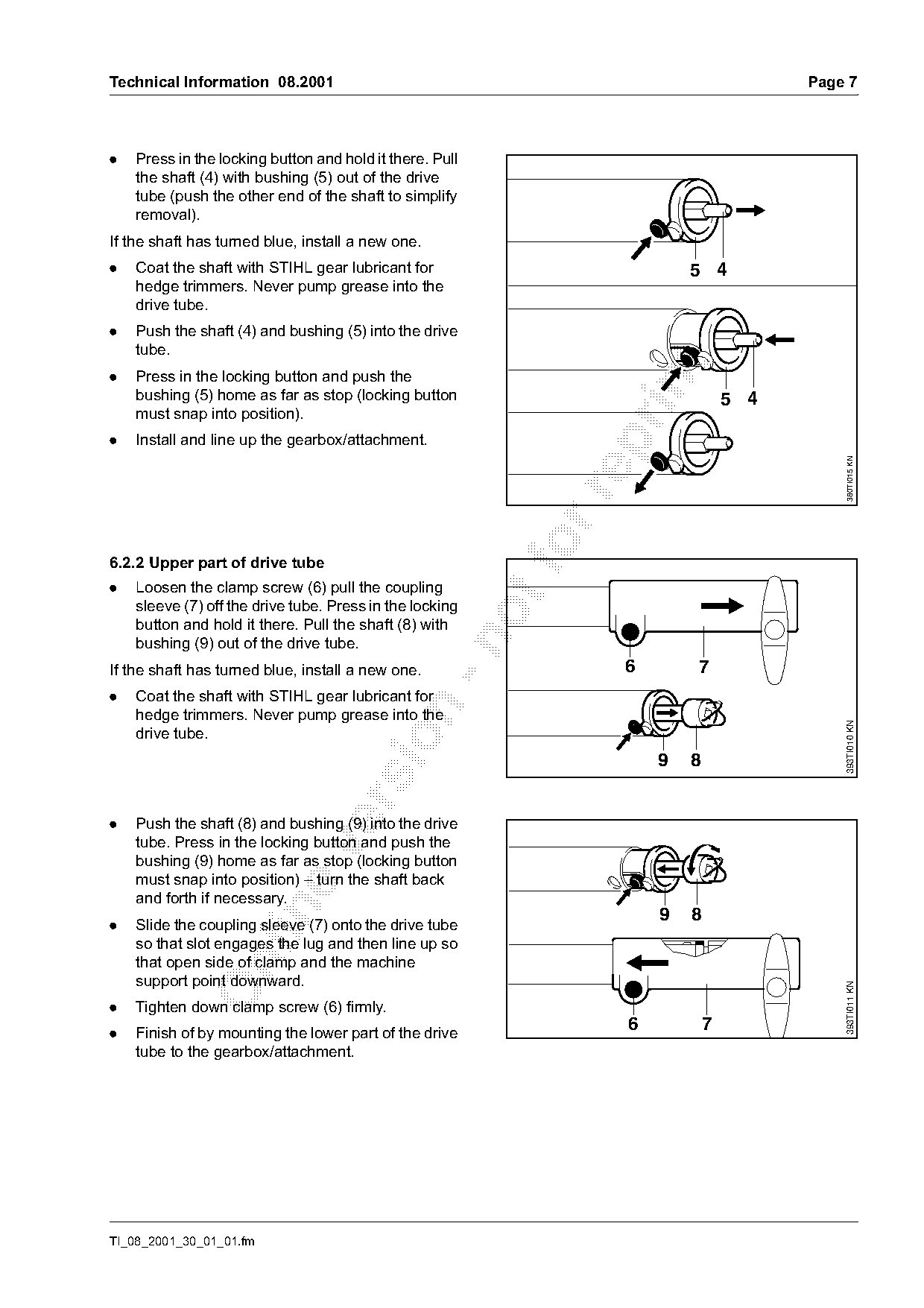
.   Press in the locking button and hold it there. Pull
    the shaft (4) with bushing (5) out of the drive
    tube (push the other end of the shaft to simplify
    removal).
If the shaft has turned blue, install a new one.
.   Coat the shaft with STIHL gear lubricant for                         5 4
    hedge trimmers. Never pump grease into the
    drive tube.
.   Push the shaft (4) and bushing (5) into the drive
    tube.

.   Press in the locking button and push the

    bushing (5) home as far as stop (locking button                              5 4
    must snap into position).
.   Install and line up the gearbox/attachment.

                                                                                            380TI015 KN
6.2.2 Upper part of drive tube
.   Loosen the clamp screw (6) pull the coupling
    sleeve (7) off the drive tube. Press in the locking
    button and hold it there. Pull the shaft (8) with

    bushing (9) out of the drive tube.
If the shaft has turned blue, install a new one.                 6       7
.   Coat the shaft with STIHL gear lubricant for

    hedge trimmers. Never pump grease into the

                                                                                           393TI010 KN
    drive tube.

                                                                     9   8

.   Push the shaft (8) and bushing (9) into the drive
    tube. Press in the locking button and push the

    bushing (9) home as far as stop (locking button
    must snap into position) – turn the shaft back
    and forth if necessary.

                                                                     9   8
.   Slide the coupling sleeve (7) onto the drive tube
    so that slot engages the lug and then line up so
    that open side of clamp and the machine

    support point downward.
                                                                                           393TI011 KN

.   Tighten down clamp screw (6) firmly.
.   Finish of by mounting the lower part of the drive
                                                                 6           7
    tube to the gearbox/attachment.

TI_08_2001_30_01_01.fm
Page 8 of 8
Text of page 8 — search, copy, screen readers
Page 8                                                                       Technical Information 08.2001

6.3   Tightening Torques
The tightening torques for the powerhead are listed
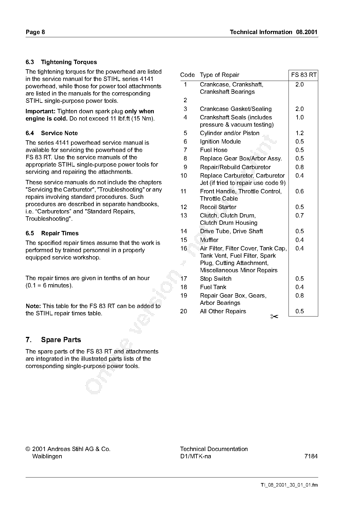
                                                           Code Type of Repair                         FS 83 RT
in the service manual for the STIHL series 4141
powerhead, while those for power tool attachments           1    Crankcase, Crankshaft,                 2.0
are listed in the manuals for the corresponding                  Crankshaft Bearings
STIHL single-purpose power tools.                           2
Important: Tighten down spark plug only when                3    Crankcase Gasket/Sealing               2.0
engine is cold. Do not exceed 11 lbf.ft (15 Nm).            4    Crankshaft Seals (includes             1.0
                                                                 pressure & vacuum testing)
6.4   Service Note                                          5    Cylinder and/or Piston                 1.2
The series 4141 powerhead service manual is                 6    Ignition Module                        0.5

available for servicing the powerhead of the                7    Fuel Hose                              0.5
FS 83 RT. Use the service manuals of the                    8    Replace Gear Box/Arbor Assy.           0.5
appropriate STIHL single-purpose power tools for            9    Repair/Rebuild Carburetor              0.8
servicing and repairing the attachments.

                                                           10    Replace Carburetor, Carburetor         0.4
These service manuals do not include the chapters                Jet (if tried to repair use code 9)
"Servicing the Carburetor", "Troubleshooting" or any       11    Front Handle, Throttle Control,        0.6

repairs involving standard procedures. Such                      Throttle Cable
procedures are described in separate handbooks,
                                                           12    Recoil Starter                         0.5
i.e. “Carburetors” and "Standard Repairs,
Troubleshooting".
                                                           13     fo
                                                                 Clutch, Clutch Drum,
                                                                 Clutch Drum Housing
                                                                                                        0.7

6.5   Repair Times                                         14    Drive Tube, Drive Shaft                0.5
The specified repair times assume that the work is         15    Muffler                                0.4
performed by trained personnel in a properly               16    Air Filter, Filter Cover, Tank Cap,    0.4

equipped service workshop.                                       Tank Vent, Fuel Filter, Spark
                                                                 Plug, Cutting Attachment,
                                                                 Miscellaneous Minor Repairs

The repair times are given in tenths of an hour            17    Stop Switch                            0.5
(0.1 = 6 minutes).                                         18    Fuel Tank                              0.4

                                                           19    Repair Gear Box, Gears,                0.8
                                                                 Arbor Bearings
Note: This table for the FS 83 RT can be added to
the STIHL repair times table.                              20    All Other Repairs                      0.5

                                                                                             ✂

7.    Spare Parts
The spare parts of the FS 83 RT and attachments

are integrated in the illustrated parts lists of the
corresponding single-purpose power tools.

© 2001 Andreas Stihl AG & Co.                              Technical Documentation
  Waiblingen                                               D1/MTK-na                                          7184

                                                                                         TI_08_2001_30_01_01.fm
Most of these PDFs embed fonts with a shifted character map, so the text above was recovered rather than copied — read it as a faithful but imperfect transcription, and treat the page image above each block as the authority where the two disagree — the figures exist only there, because they are vector drawings that text extraction cannot keep.