Technical Information · issue 14 of 2001
New Sales Designation for STIHL 019 T; Fan Housing
Model 019 T / MS 191 T Chainsaws – Series 1132
IssueTI 14/2001
Engine family 1132
Part changes (1)
| Was | Becomes | What the bulletin says |
|---|---|---|
| 1132 120 0603 | 1132 120 0604 | The previous carburetor 1132 120 0603 will be replaced by carburetor 1132 120 0604 from serial number 2 48 938 259 . |
Full text
Page 1 of 4
Text of page 1 — search, copy, screen readers
Technical Information

                                                                                14.2001
Model 019 T / MS 191 T Chainsaws – Series 1132

Contents
1.   New Sales Designation for STIHL 019 T
2.   Fan Housing, Nameplate

3.   Carburetor

4.   Spare Parts
5.   Repair Times

1.    New Sales Designation for
      STIHL 019 T

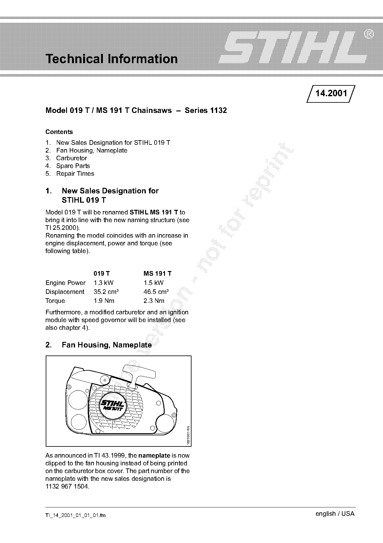
Model 019 T will be renamed STIHL MS 191 T to
bring it into line with the new naming structure (see
TI 25.2000).
Renaming the model coincides with an increase in
engine displacement, power and torque (see
following table).

                 019 T              MS 191 T
Engine Power     1.3 kW             1.5 kW
Displacement     35.2 cm³           46.5 cm³

Torque           1.9 Nm             2.3 Nm

Furthermore, a modified carburetor and an ignition
module with speed governor will be installed (see
also chapter 4).

2.    Fan Housing, Nameplate

                                                    163TI001 KN

As announced in TI 43.1999, the nameplate is now
clipped to the fan housing instead of being printed
on the carburetor box cover. The part number of the
nameplate with the new sales designation is
1132 967 1504.

TI_14_2001_01_01_01.fm                                                          english / USA
Page 2 of 4
Text of page 2 — search, copy, screen readers
Page 2                                                                                    Technical Information 14.2001

3.     Carburetor                                                    3.2     Function

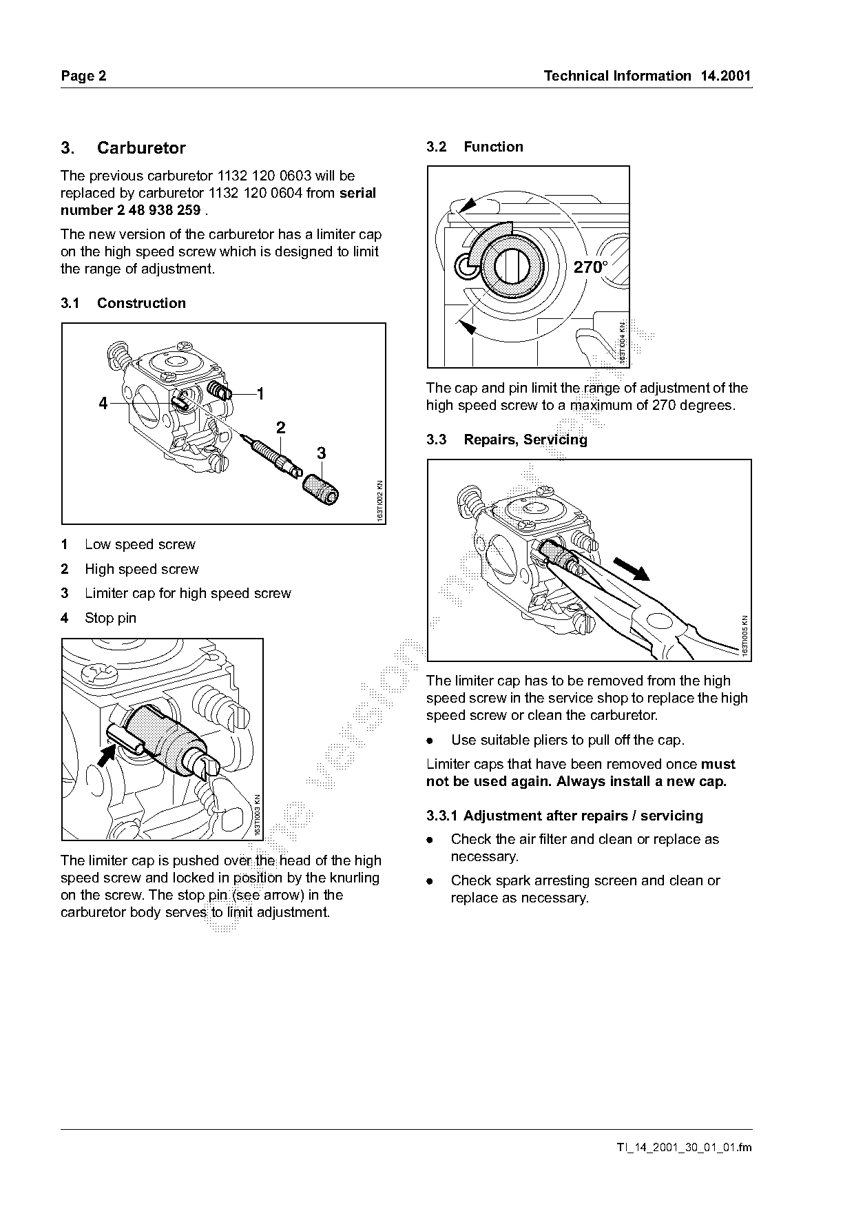
The previous carburetor 1132 120 0603 will be
replaced by carburetor 1132 120 0604 from serial
number 2 48 938 259 .
The new version of the carburetor has a limiter cap
on the high speed screw which is designed to limit
the range of adjustment.                                                                        270°

3.1    Construction

                                                                                                       163TI004 KN

                                   1                                 The cap and pin limit the range of adjustment of the
        4                                                            high speed screw to a maximum of 270 degrees.

                                              2
                                                                     3.3     Repairs, Servicing
                                                  3

                                                       163TI002 KN

1     Low speed screw
2     High speed screw
3     Limiter cap for high speed screw

4     Stop pin

                                                                                                                           163TI005 KN

                                                                     The limiter cap has to be removed from the high

                                                                     speed screw in the service shop to replace the high
                                                                     speed screw or clean the carburetor.
                                                                     .     Use suitable pliers to pull off the cap.

                                                                     Limiter caps that have been removed once must
                                                                     not be used again. Always install a new cap.
                                163TI003 KN

                                                                     3.3.1 Adjustment after repairs / servicing
                                                                     .     Check the air filter and clean or replace as

The limiter cap is pushed over the head of the high                        necessary.
speed screw and locked in position by the knurling                   .     Check spark arresting screen and clean or

on the screw. The stop pin (see arrow) in the                              replace as necessary.
carburetor body serves to limit adjustment.

                                                                                                       TI_14_2001_30_01_01.fm
Page 3 of 4
Text of page 3 — search, copy, screen readers
Technical Information 14.2001                                                                          Page 3

3.3.2 Standard setting of H screw                      3.3.4 Adjusting idle speed

                 H       L                                                      L

                                163TI006 KN

                                                                                         163TI008 KN
                                                                  LA

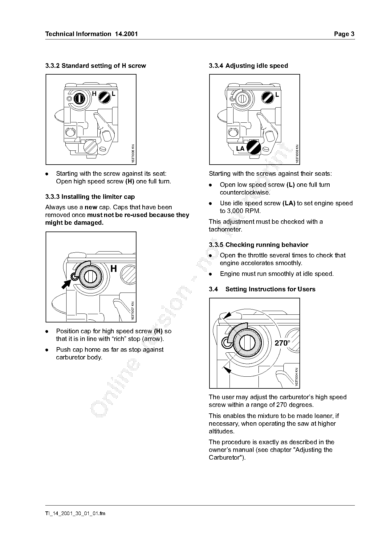
.   Starting with the screw against its seat:          Starting with the screws against their seats:
    Open high speed screw (H) one full turn.

                                                       .     Open low speed screw (L) one full turn
                                                             counterclockwise.
3.3.3 Installing the limiter cap
                                                       .     Use idle speed screw (LA) to set engine speed

Always use a new cap. Caps that have been
                                                             to 3,000 RPM.
removed once must not be re-used because they
might be damaged.                                      This adjustment must be checked with a
                                                       tachometer.

                                                       3.3.5 Checking running behavior
                                                       .     Open the throttle several times to check that
                                                             engine accelerates smoothly.

                         H                             .     Engine must run smoothly at idle speed.

                                                       3.4    Setting Instructions for Users
                                163TI007 KN

.   Position cap for high speed screw (H) so

    that it is in line with “rich” stop (arrow).
                                                                                270°
.   Push cap home as far as stop against

    carburetor body.
                                                                                        163TI004 KN

                                                       The user may adjust the carburetor’s high speed

                                                       screw within a range of 270 degrees.
                                                       This enables the mixture to be made leaner, if
                                                       necessary, when operating the saw at higher
                                                       altitudes.
                                                       The procedure is exactly as described in the
                                                       owner’s manual (see chapter "Adjusting the
                                                       Carburetor").

TI_14_2001_30_01_01.fm
Page 4 of 4
Text of page 4 — search, copy, screen readers
Page 4                                                                         Technical Information 14.2001

4.     Spare Parts
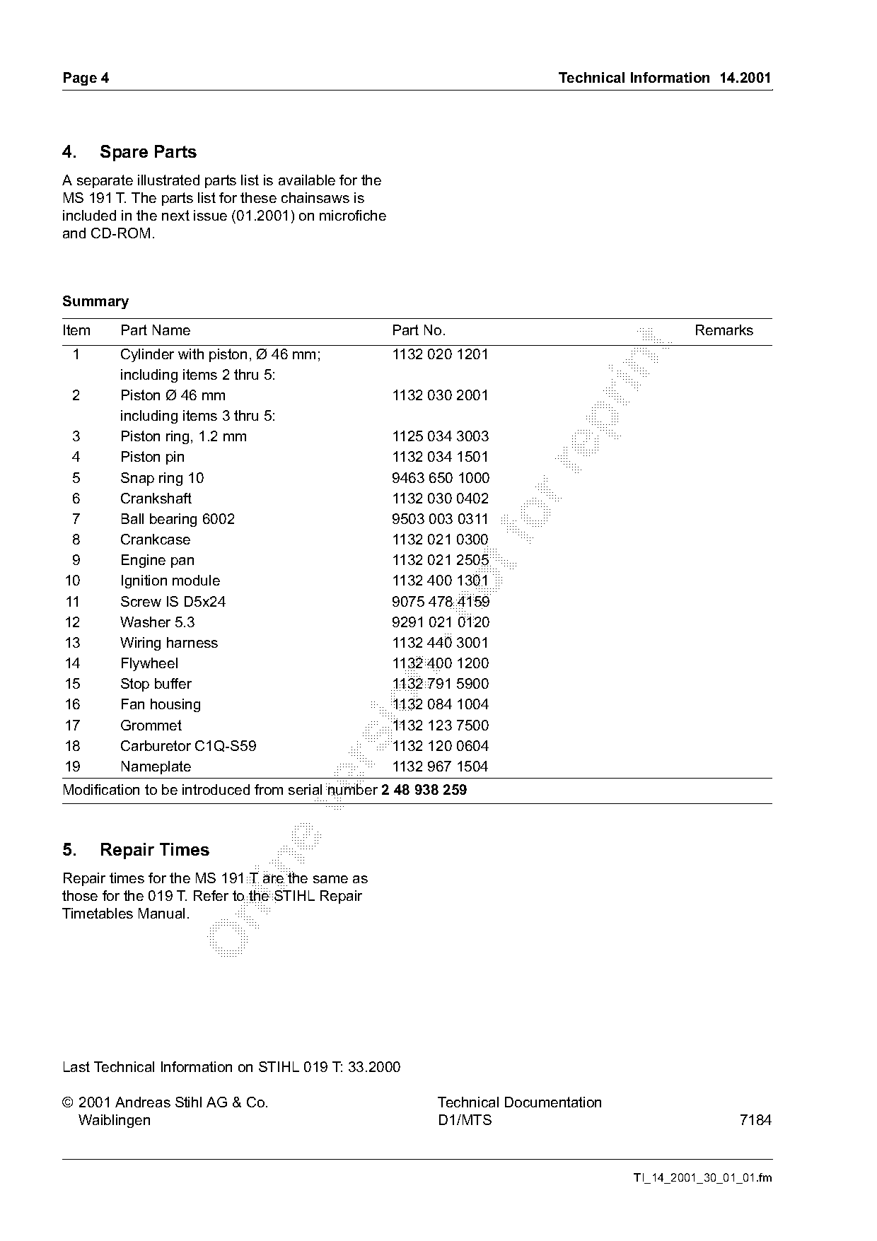
A separate illustrated parts list is available for the
MS 191 T. The parts list for these chainsaws is
included in the next issue (01.2001) on microfiche
and CD-ROM.

Summary

Item     Part Name                                       Part No.                                 Remarks

 1       Cylinder with piston, Ø 46 mm;                  1132 020 1201

         including items 2 thru 5:
 2       Piston Ø 46 mm                                  1132 030 2001
         including items 3 thru 5:

 3       Piston ring, 1.2 mm                             1125 034 3003
 4       Piston pin                                      1132 034 1501

 5       Snap ring 10                                    9463 650 1000
 6       Crankshaft                                      1132 030 0402
 7
 8
         Ball bearing 6002
         Crankcase
                                                         9503 003 0311
                                                         1132 021 0300
 9       Engine pan                                      1132 021 2505
10       Ignition module                                 1132 400 1301
11       Screw IS D5x24                                  9075 478 4159

12       Washer 5.3                                      9291 021 0120
13       Wiring harness                                  1132 440 3001
14       Flywheel                                        1132 400 1200

15       Stop buffer                                     1132 791 5900

16       Fan housing                                     1132 084 1004
17       Grommet                                         1132 123 7500
18       Carburetor C1Q-S59                              1132 120 0604

19       Nameplate                                       1132 967 1504
Modification to be introduced from serial number 2 48 938 259

5.     Repair Times

Repair times for the MS 191 T are the same as
those for the 019 T. Refer to the STIHL Repair
Timetables Manual.

Last Technical Information on STIHL 019 T: 33.2000

© 2001 Andreas Stihl AG & Co.                                  Technical Documentation
  Waiblingen                                                   D1/MTS                                    7184

                                                                                         TI_14_2001_30_01_01.fm
Most of these PDFs embed fonts with a shifted character map, so the text above was recovered rather than copied — read it as a faithful but imperfect transcription, and treat the page image above each block as the authority where the two disagree — the figures exist only there, because they are vector drawings that text extraction cannot keep.