Technical Information · issue 16 of 2001
Model Update; Cylinder; Carburetor; Ignition Module; Shroud; Nameplate; STIHL Logo; Fan Housing; Lightweight Shaft (FS 85); Lubricating the Drive Shaft
Model FH 75 Power Scythe – Series 4230
IssueTI 16/2001
Full text
Page 1 of 14
Text of page 1 — search, copy, screen readers
Technical Information

                                                                          16.2001
Model FH 75 Power Scythe                                  – Series 4230
Model HL 75, 75 K Hedge Trimmers                          – Series 4230
Model HT 70, 75 Pole Pruners                              – Series 4138
Model FC 75, 85 Power Edgers                              – Series 4137
Model KW 85 PowerSweep                                    – Series 4602

Model FS 75, 80, 85, 85 T Brushcutters                    – Series 4137

Contents

1. Model Update
2. Cylinder
    2.1 Parts Availability for Previous Machines

    2.2 Summary
3. Carburetor
    3.1 Primer Flange Mounting on Carburetor
         (Version with LD Screw)
    3.2 Carburetor with 3 Adjusting Screws
         and Caps
4. Ignition Module
    4.1 Parts Availability

    4.2 Service Notes
    4.3 STIHL BG 75 (Series 4227)
    4.4 Summary

5. Shroud
    5.1 Parts Availability

    5.2 Service Note
    5.3 Summary
6. Nameplate

7. STIHL Logo
    7.1 Service Note
    7.2 Summary

8. Fan Housing
9. Lightweight Shaft (FS 85)
    9.1 Service Note

    9.2 Summary
10. Lubricating the Drive Shaft

TI_16_2001_02_01_01.fm                                                    english / USA
Page 2 of 14
Text of page 2 — search, copy, screen readers
Page 2                                                                            Technical Information 16.2001

1.    Model Update                                             2.    Cylinder

                                                                                                                  392TI032 KN
                                                               Cylinder viewed from below
                                                               Left: Previous version

                                                               Right: New version

                                                 393TI019 KN

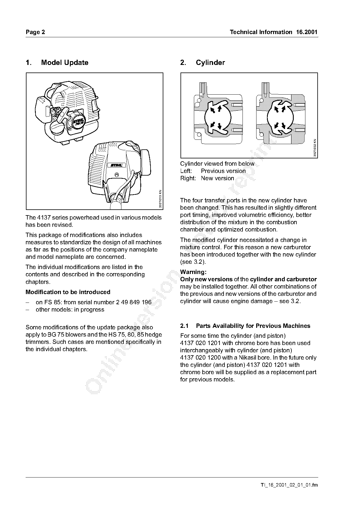
                                                               The four transfer ports in the new cylinder have
                                                               been changed. This has resulted in slightly different
The 4137 series powerhead used in various models
has been revised.
                                                               port timing, improved volumetric efficiency, better
                                                               distribution of the mixture in the combustion
                                                               chamber and optimized combustion.
This package of modifications also includes
measures to standardize the design of all machines             The modified cylinder necessitated a change in
as far as the positions of the company nameplate               mixture control. For this reason a new carburetor

and model nameplate are concerned.                             has been introduced together with the new cylinder
                                                               (see 3.2).
The individual modifications are listed in the
contents and described in the corresponding                    Warning:

chapters.                                                      Only new versions of the cylinder and carburetor
                                                               may be installed together. All other combinations of

Modification to be introduced                                  the previous and new versions of the carburetor and
–    on FS 85: from serial number 2 49 849 196                 cylinder will cause engine damage – see 3.2.
–    other models: in progress

Some modifications of the update package also                  2.1   Parts Availability for Previous Machines

apply to BG 75 blowers and the HS 75, 80, 85 hedge             For some time the cylinder (and piston)
trimmers. Such cases are mentioned specifically in             4137 020 1201 with chrome bore has been used
the individual chapters.                                       interchangeably with cylinder (and piston)

                                                               4137 020 1200 with a Nikasil bore. In the future only
                                                               the cylinder (and piston) 4137 020 1201 with
                                                               chrome bore will be supplied as a replacement part

                                                               for previous models.

                                                                                              TI_16_2001_02_01_01.fm
Page 3 of 14
Text of page 3 — search, copy, screen readers
Technical Information 16.2001                                                                                     Page 3

2.1.1 STIHL HS 75, 80, 85 (Series 4226)
This modification has been introduced on the
production line and in parts support for these
machines.

2.2    Summary

Item     Part Name                                         Previous               New                      Remarks
 1       Cylinder with piston                              4137 020 1200          4137 020 1201            1)2)
 2       Cylinder with piston                              ---                    4137 020 1202            3)

         including parts as before
Modification to be introduced: see chapter 1
Remarks

1) see 2.1
2) Previous version of part will be supplied from factory only as long as existing stocks last
3) New version cylinder only for use on machines with 3 carburetor adjustment screws and limiter caps.

3.     Carburetor

3.1    Primer Flange Mounting on Carburetor

       (Version with LD Screw)
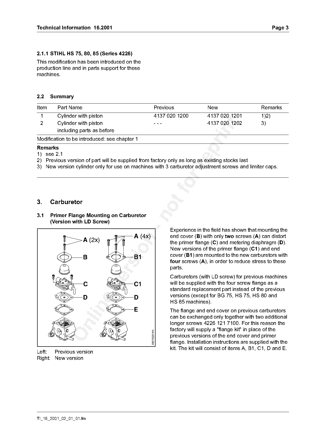
                                                                 Experience in the field has shown that mounting the
                                          A (4x)                 end cover (B) with only two screws (A) can distort

                     A (2x)                                      the primer flange (C) and metering diaphragm (D).
                                                                 New versions of the primer flange (C1) and end

                     B                     B1                    cover (B1) are mounted to the new carburetors with
                                                                 four screws (A), in order to reduce stress to these
                                                                 parts.

                                                                 Carburetors (with LD screw) for previous machines
                     C                     C1                    will be supplied with the four screw flange as a

                                                                 standard replacement part instead of the previous
                     D                     D                     versions (except for BG 75, HS 75, HS 80 and
                                                                 HS 85 machines).

                                           E                     The flange and end cover on previous carburetors
                                                                 can be exchanged only together with two additional
                                                                 longer screws 4226 121 7100. For this reason the

                                                                 factory will supply a "flange kit" in place of the
                                                   393TI020 KN

                                                                 previous versions of the end cover and primer
                                                                 flange. Installation instructions are supplied with the
                                                                 kit. The kit will consist of items A, B1, C1, D and E.
Left: Previous version
Right: New version

TI_16_2001_02_01_01.fm
Page 4 of 14
Text of page 4 — search, copy, screen readers
Page 4                                                                         Technical Information 16.2001

3.1.1 Parts availability                                  3.1.3 STIHL HS 75, 80 and 85 (Series 4226)
The new flanges are to be used as spare parts for all     The previous version carburetor for these models
Zama C1Q carburetors with LD adjusting screw              has not yet been changed over to the four-screw
(BIS carburetor).                                         flange.
                                                          However, for spare parts purposes, the factory only
                                                          supplies the new "flange kit“ for mounting the flange
3.1.2 BG 75 (Series 4227)                                 with four screws.
The replacement carburetor for this model was not
changed over to the four screw flange.
However, for spare parts purposes, a new "flange          3.1.4 Installation

kit" for mounting the flange with four screws is          Insert screws (see illustration, page 3, item A) until

available.                                                "finger tight", then finally tightened them down
                                                          alternately in a diagonal pattern.

3.1.5 Summary

Item     Part Name                                  Previous               New                     Remarks
         FC 75, 85, FH 75, FS 75, 80, 85, 85 T,
         HL 75, 75 K, HT 70, 75, KW 85
 1       Carburetor C1Q-S45                         4137 120 0603          use item 2               1)
         with 2 screw primer end cover;
         including items 4 to 9:

 2       Carburetor C1Q-S56                         ---                    4137 120 0604
         with 4 screw primer end cover;
         including item 3:

 3       Flange kit;                                ---                    4140 120 2250
         consisting of items 4 to 7 and 9:

 4       End cover                                  4226 121 0800          -*-                      2)3)
 5       Flange                                     4226 120 2200          use item 3               3)
 6       Metering diaphragm                         4129 121 4700          4129 121 4700

 7       Gasket                                     4129 129 0902          4129 129 0902
 8       Screw (2x)                                 1128 122 7100          ---

 9       Screw (4x)                                 4226 122 7100          4226 122 7100           4)

         BG 75

10       Carburetor C1Q-S30                         4227 120 0602          -*-                      5)
         with 2 screw primer end cover;

         including items 4, 6 to 9 and 12:
11       Flange kit;                                ---                    4227 120 2250
         consisting of items 4, 6, 7, 9, 12:
12       Flange                                     4227 120 2200          use item 11              3)
13       Support;                                   4227 700 8450          4227 700 8450            5)
         including item 11:

                                                                                          TI_16_2001_02_01_01.fm
Page 5 of 14
Text of page 5 — search, copy, screen readers
Technical Information 16.2001                                                                                        Page 5

Item       Part Name                                           Previous                  New                 Remarks
           HS 75, 80, 85
14         Carburetor C1Q-S29 (w/ governor                     4226 120 0602             ---                 5)6)
           valve) with 2 screw primer end cover;
           including items 4 to 9:
15         Carburetor C1Q-S42 (no governor                     4226 120 0604             -*-                 5)7)
           valve) with 2 screw primer end cover;
           including items 4 to 9:
16         Flange kit, see item 3:                             ---                       4140 120 2250
           all other parts as before

Remarks

1) Previous version of part will be supplied from factory only as long as existing stocks last
2) Previous version of part remains available as spare for other models
3) New version of part not available as separate item

4) Quantity increased from 2 to 4
5) Unmodified version of part will be supplied until existing stocks are exhausted
6) Version with governor valve

7) Version without governor valve

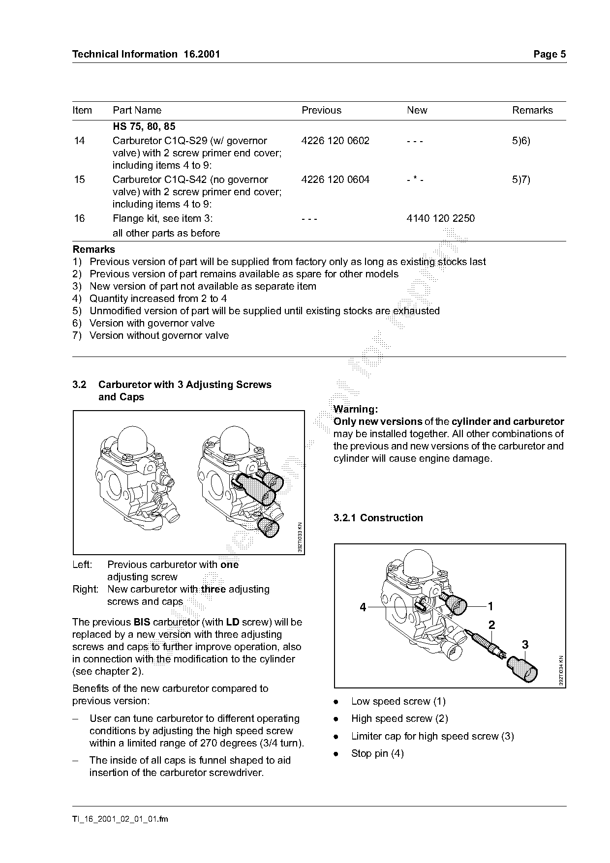
3.2     Carburetor with 3 Adjusting Screws
        and Caps
                                                                     Warning:
                                                                     Only new versions of the cylinder and carburetor

                                                                     may be installed together. All other combinations of
                                                                     the previous and new versions of the carburetor and
                                                                     cylinder will cause engine damage.

                                                                     3.2.1 Construction
                                                       392TI033 KN

Left:  Previous carburetor with one
       adjusting screw
Right: New carburetor with three adjusting

       screws and caps
                                                                           4                             1
The previous BIS carburetor (with LD screw) will be                                                      2
replaced by a new version with three adjusting

screws and caps to further improve operation, also                                                               3
in connection with the modification to the cylinder
                                                                                                                         392TI034 KN

(see chapter 2).
Benefits of the new carburetor compared to
previous version:                                                    .    Low speed screw (1)
–     User can tune carburetor to different operating                .    High speed screw (2)
      conditions by adjusting the high speed screw
                                                                     .    Limiter cap for high speed screw (3)
      within a limited range of 270 degrees (3/4 turn).
                                                                     .    Stop pin (4)
–     The inside of all caps is funnel shaped to aid
      insertion of the carburetor screwdriver.

TI_16_2001_02_01_01.fm
Page 6 of 14
Text of page 6 — search, copy, screen readers
Page 6                                                                  Technical Information 16.2001

                                                        3.2.3 Repairs, servicing

                                 295TI012 KN

                                                                                                                392TI036 KN
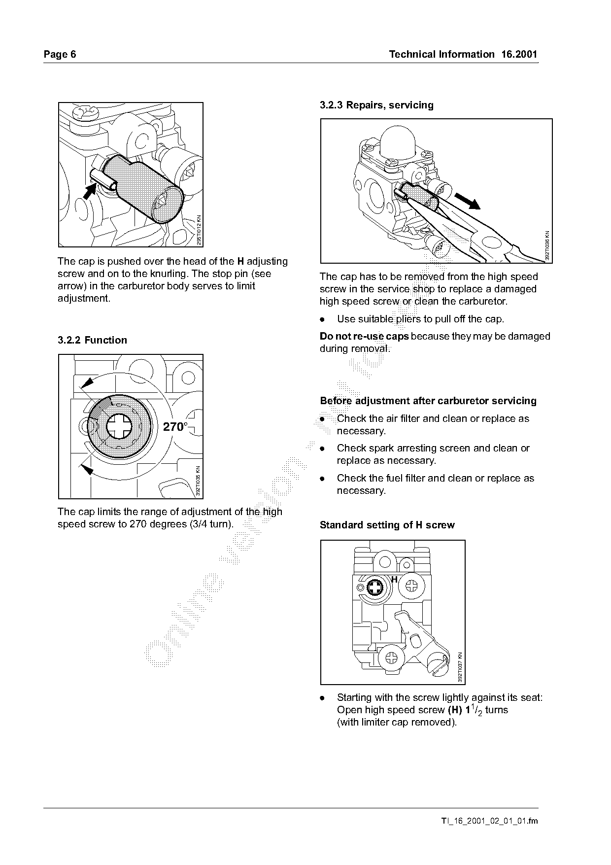
  The cap is pushed over the head of the H adjusting
  screw and on to the knurling. The stop pin (see       The cap has to be removed from the high speed
  arrow) in the carburetor body serves to limit         screw in the service shop to replace a damaged

  adjustment.                                           high speed screw or clean the carburetor.
                                                        .   Use suitable pliers to pull off the cap.

  3.2.2 Function                                        Do not re-use caps because they may be damaged
                                                        during removal.
                                                        Before adjustment after carburetor servicing
                                                        .   Check the air filter and clean or replace as

                         270°                               necessary.
                                                        .   Check spark arresting screen and clean or
                                                            replace as necessary.
                                392TI035 KN

                                                        .   Check the fuel filter and clean or replace as

                                                            necessary.

  The cap limits the range of adjustment of the high
  speed screw to 270 degrees (3/4 turn).                Standard setting of H screw


                                                                                        392TI037 KN

                                                        .   Starting with the screw lightly against its seat:
                                                            Open high speed screw (H) 11/2 turns
                                                            (with limiter cap removed).

                                                                                    TI_16_2001_02_01_01.fm
Page 7 of 14
Text of page 7 — search, copy, screen readers
Technical Information 16.2001                                                                                    Page 7

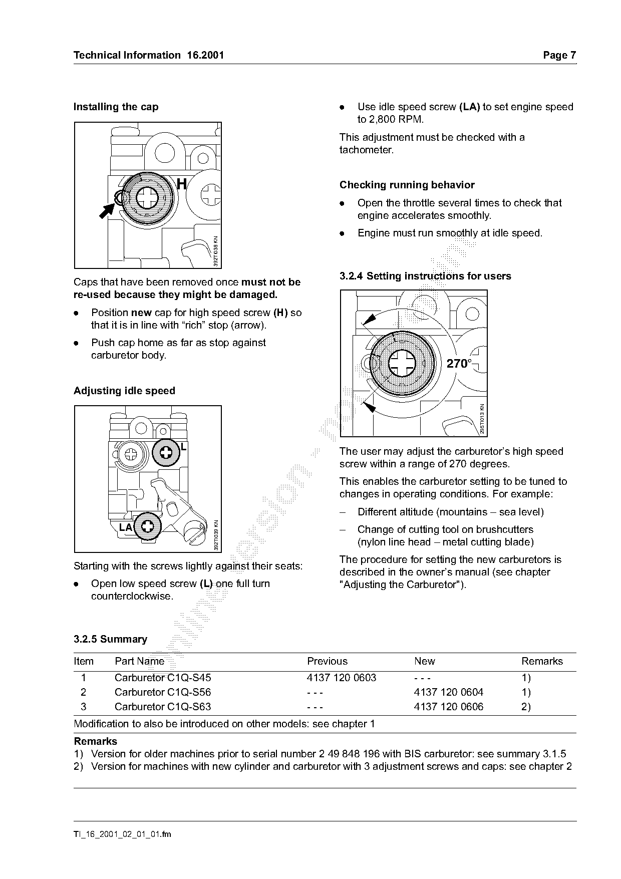
Installing the cap                                            .    Use idle speed screw (LA) to set engine speed
                                                                   to 2,800 RPM.
                                                              This adjustment must be checked with a
                                                              tachometer.

                          H                                   Checking running behavior
                                                              .    Open the throttle several times to check that
                                                                   engine accelerates smoothly.
                                                              .    Engine must run smoothly at idle speed.
                                 392TI038 KN

                                                              3.2.4 Setting instructions for users
Caps that have been removed once must not be
re-used because they might be damaged.

.       Position new cap for high speed screw (H) so
        that it is in line with “rich” stop (arrow).

.       Push cap home as far as stop against
        carburetor body.
                                                                  fo                   270°

Adjusting idle speed

                                                                                              295TI013 KN

                          L                                   The user may adjust the carburetor’s high speed
                                                              screw within a range of 270 degrees.

                                                              This enables the carburetor setting to be tuned to
                                                              changes in operating conditions. For example:

                                                              –    Different altitude (mountains – sea level)
                                  392TI039 KN

             LA                                               –    Change of cutting tool on brushcutters

                                                                   (nylon line head – metal cutting blade)
                                                              The procedure for setting the new carburetors is
Starting with the screws lightly against their seats:

                                                              described in the owner’s manual (see chapter
.       Open low speed screw (L) one full turn                "Adjusting the Carburetor").
        counterclockwise.

3.2.5 Summary

Item        Part Name                                   Previous               New                          Remarks
    1       Carburetor C1Q-S45                          4137 120 0603          ---                          1)
    2       Carburetor C1Q-S56                          ---                    4137 120 0604                1)
    3       Carburetor C1Q-S63                          ---                    4137 120 0606                2)
Modification to also be introduced on other models: see chapter 1
Remarks
1) Version for older machines prior to serial number 2 49 848 196 with BIS carburetor: see summary 3.1.5
2) Version for machines with new cylinder and carburetor with 3 adjustment screws and caps: see chapter 2

TI_16_2001_02_01_01.fm
Page 8 of 14
Text of page 8 — search, copy, screen readers
Page 8                                                                               Technical Information 16.2001

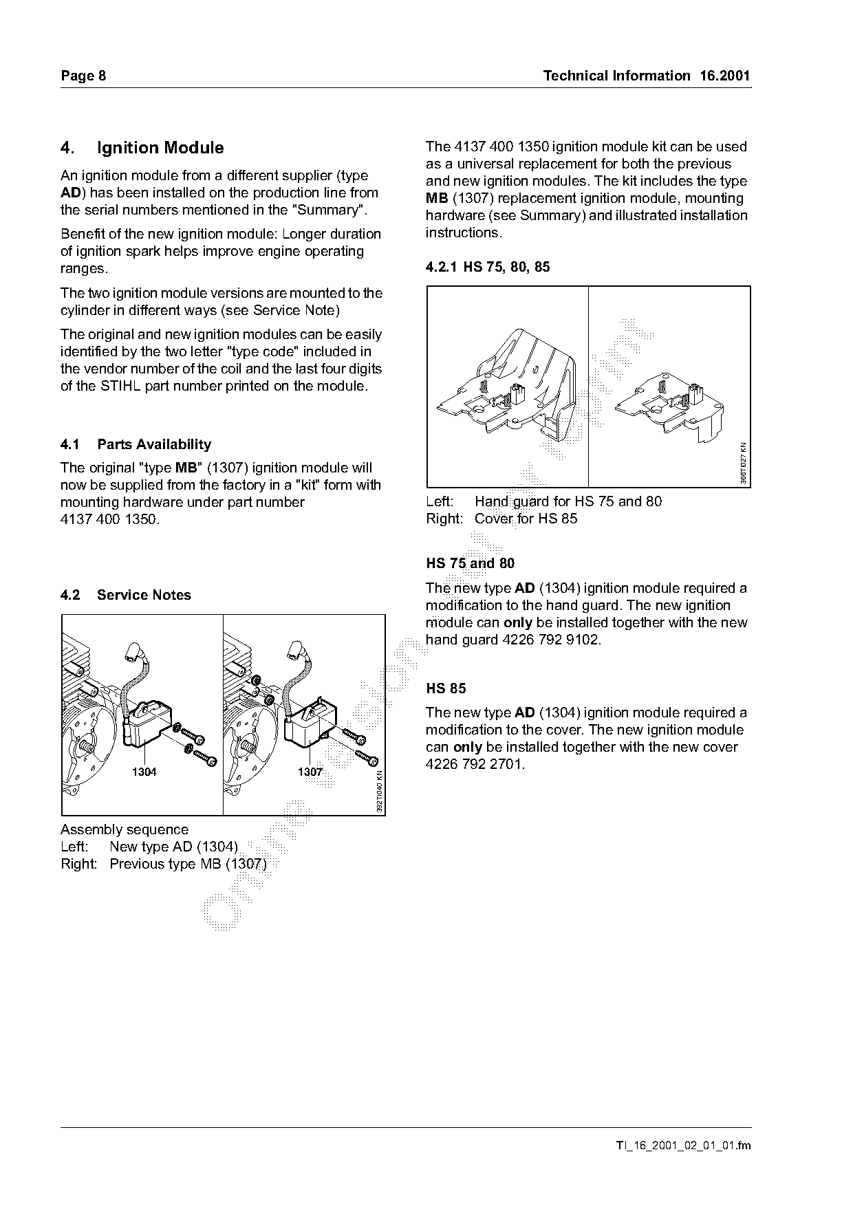
4.    Ignition Module                                              The 4137 400 1350 ignition module kit can be used
                                                                   as a universal replacement for both the previous
An ignition module from a different supplier (type                 and new ignition modules. The kit includes the type
AD) has been installed on the production line from                 MB (1307) replacement ignition module, mounting
the serial numbers mentioned in the "Summary".                     hardware (see Summary) and illustrated installation
Benefit of the new ignition module: Longer duration                instructions.
of ignition spark helps improve engine operating
ranges.                                                            4.2.1 HS 75, 80, 85
The two ignition module versions are mounted to the
cylinder in different ways (see Service Note)
The original and new ignition modules can be easily

identified by the two letter "type code" included in

the vendor number of the coil and the last four digits
of the STIHL part number printed on the module.

4.1   Parts Availability

                                                                                                                     366TI027 KN
The original "type MB" (1307) ignition module will
now be supplied from the factory in a "kit" form with
mounting hardware under part number
4137 400 1350.
                                                                   Left: Hand guard for HS 75 and 80
                                                                   Right: Cover for HS 85
                                                                   HS 75 and 80
                                                                   The new type AD (1304) ignition module required a

4.2   Service Notes
                                                                   modification to the hand guard. The new ignition
                                                                   module can only be installed together with the new
                                                                   hand guard 4226 792 9102.

                                                                   HS 85
                                                                   The new type AD (1304) ignition module required a
                                                                   modification to the cover. The new ignition module

                                                                   can only be installed together with the new cover
           1304                        1307
                                                                   4226 792 2701.
                                                     392TI040 KN

Assembly sequence

Left: New type AD (1304)
Right: Previous type MB (1307)

                                                                                                 TI_16_2001_02_01_01.fm
Page 9 of 14
Text of page 9 — search, copy, screen readers
Technical Information 16.2001                                                                        Page 9

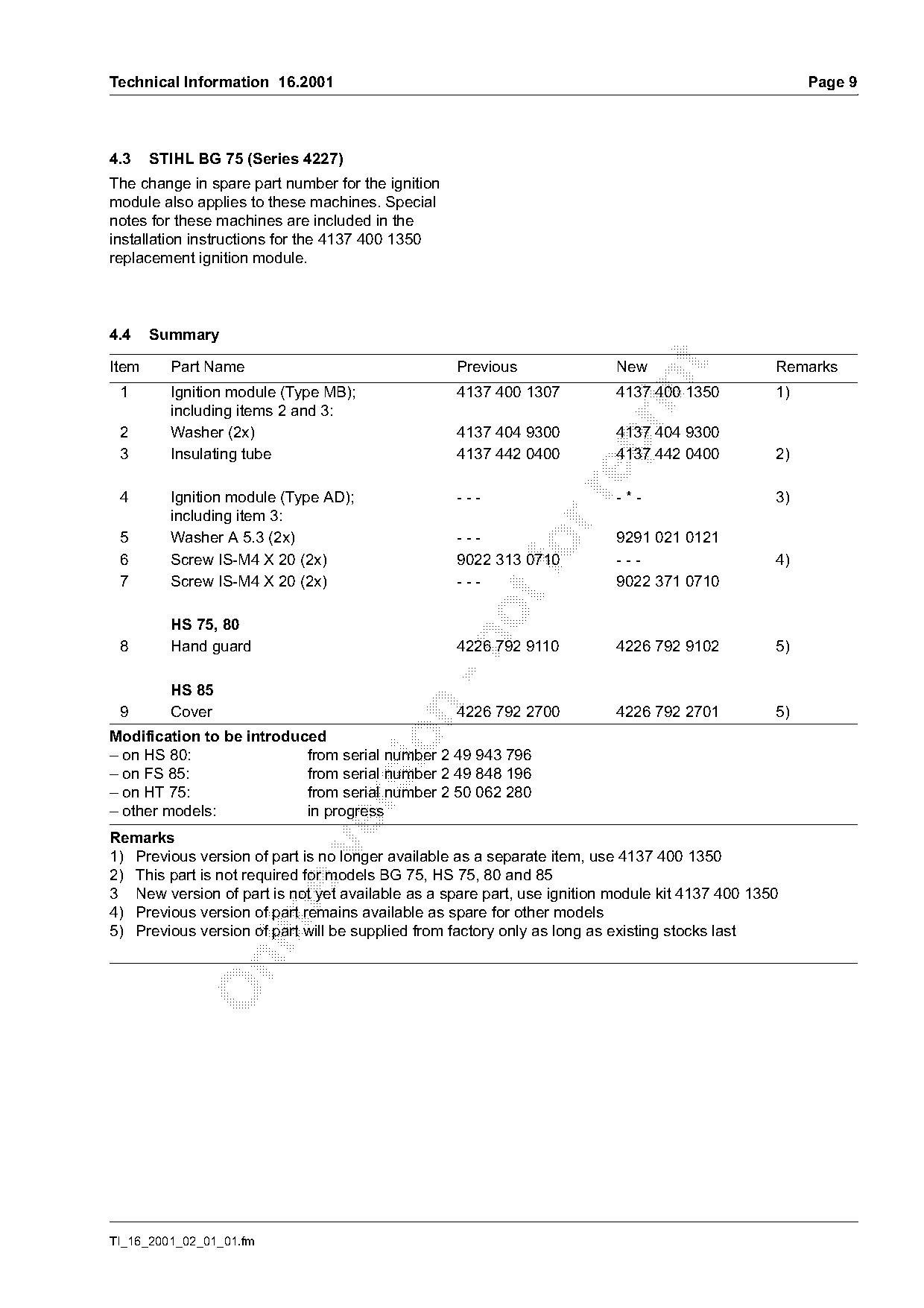
4.3    STIHL BG 75 (Series 4227)
The change in spare part number for the ignition
module also applies to these machines. Special
notes for these machines are included in the
installation instructions for the 4137 400 1350
replacement ignition module.

4.4    Summary

Item     Part Name                                 Previous              New                    Remarks

 1       Ignition module (Type MB);                4137 400 1307         4137 400 1350          1)
         including items 2 and 3:
 2       Washer (2x)                               4137 404 9300         4137 404 9300

 3       Insulating tube                           4137 442 0400         4137 442 0400          2)

 4       Ignition module (Type AD);                ---                   -*-                    3)
         including item 3:
 5       Washer A 5.3 (2x)                         ---                   9291 021 0121
 6       Screw IS-M4 X 20 (2x)
                                                   9022 313 0710         ---                    4)
 7       Screw IS-M4 X 20 (2x)                     ---                   9022 371 0710

         HS 75, 80

 8       Hand guard                                4226 792 9110         4226 792 9102          5)

         HS 85

 9       Cover                                     4226 792 2700         4226 792 2701          5)
Modification to be introduced

– on HS 80:                from serial number 2 49 943 796
– on FS 85:                from serial number 2 49 848 196
– on HT 75:                from serial number 2 50 062 280

– other models:            in progress
Remarks

1) Previous version of part is no longer available as a separate item, use 4137 400 1350
2) This part is not required for models BG 75, HS 75, 80 and 85
3 New version of part is not yet available as a spare part, use ignition module kit 4137 400 1350

4) Previous version of part remains available as spare for other models
5) Previous version of part will be supplied from factory only as long as existing stocks last

TI_16_2001_02_01_01.fm
Page 10 of 14
Text of page 10 — search, copy, screen readers
Page 10                                                                                  Technical Information 16.2001

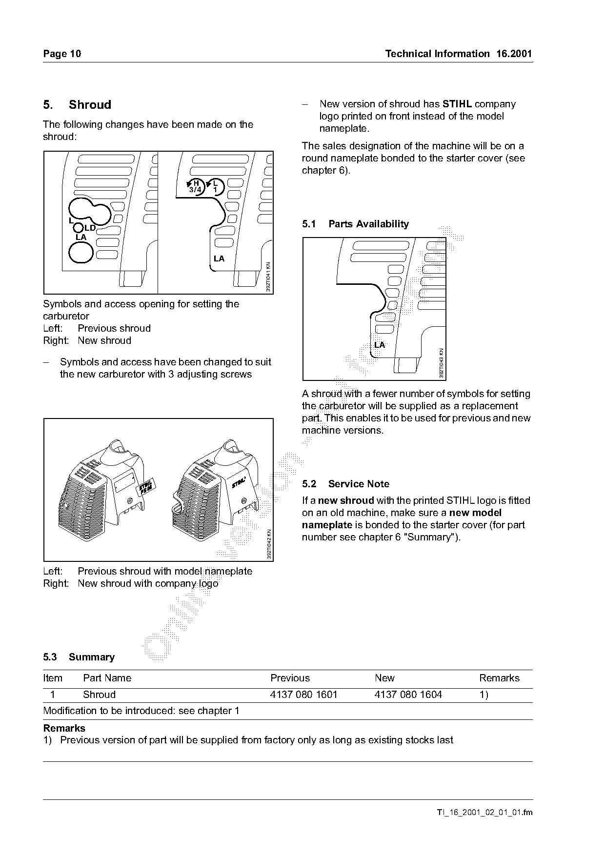
5.       Shroud                                                    –     New version of shroud has STIHL company
                                                                         logo printed on front instead of the model
The following changes have been made on the                              nameplate.
shroud:
                                                                   The sales designation of the machine will be on a
                                                                   round nameplate bonded to the starter cover (see
                                                                   chapter 6).
                                   H     L
                                  3 /4   1

         L                                                         5.1    Parts Availability
               LD
             LA

                                         LA
                                                   392TI041 KN

Symbols and access opening for setting the
carburetor

Left: Previous shroud
Right: New shroud                                                                   LA

                                                                                                   392TI043 KN
–       Symbols and access have been changed to suit
        the new carburetor with 3 adjusting screws
                                                                   A shroud with a fewer number of symbols for setting
                                                                   the carburetor will be supplied as a replacement
                                                                   part. This enables it to be used for previous and new

                                                                   machine versions.

                                                                   5.2    Service Note
                                                                   If a new shroud with the printed STIHL logo is fitted
                                                                   on an old machine, make sure a new model
                                                                   nameplate is bonded to the starter cover (for part
                                                     392TI042 KN

                                                                   number see chapter 6 "Summary").

Left: Previous shroud with model nameplate
Right: New shroud with company logo

5.3      Summary

Item          Part Name                                     Previous                New                          Remarks
    1         Shroud                                         4137 080 1601          4137 080 1604                1)
Modification to be introduced: see chapter 1
Remarks
1) Previous version of part will be supplied from factory only as long as existing stocks last

                                                                                                   TI_16_2001_02_01_01.fm
Page 11 of 14
Text of page 11 — search, copy, screen readers
Technical Information 16.2001                                                                             Page 11

6.     Nameplate
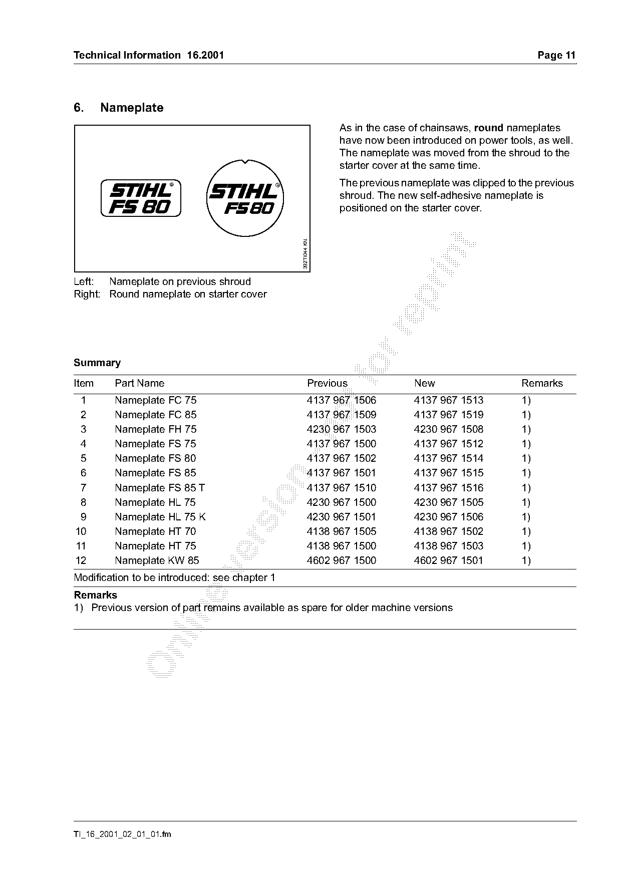
                                                               As in the case of chainsaws, round nameplates
                                                               have now been introduced on power tools, as well.
                                                               The nameplate was moved from the shroud to the
                                                               starter cover at the same time.
                                                               The previous nameplate was clipped to the previous
                                                               shroud. The new self-adhesive nameplate is
                                                               positioned on the starter cover.

                                                 392TI044 KN

Left: Nameplate on previous shroud
Right: Round nameplate on starter cover

Summary

Item     Part Name
                                                         Previous             New                    Remarks
 1       Nameplate FC 75                                 4137 967 1506        4137 967 1513          1)
 2       Nameplate FC 85                                 4137 967 1509        4137 967 1519          1)
 3       Nameplate FH 75                                 4230 967 1503        4230 967 1508          1)

 4       Nameplate FS 75                                 4137 967 1500        4137 967 1512          1)
 5       Nameplate FS 80                                 4137 967 1502        4137 967 1514          1)
 6       Nameplate FS 85                                 4137 967 1501        4137 967 1515          1)

 7       Nameplate FS 85 T                               4137 967 1510        4137 967 1516          1)

 8       Nameplate HL 75                                 4230 967 1500        4230 967 1505          1)
 9       Nameplate HL 75 K                               4230 967 1501        4230 967 1506          1)
10       Nameplate HT 70                                 4138 967 1505        4138 967 1502          1)

11       Nameplate HT 75                                 4138 967 1500        4138 967 1503          1)
12       Nameplate KW 85                                 4602 967 1500        4602 967 1501          1)

Modification to be introduced: see chapter 1
Remarks
1) Previous version of part remains available as spare for older machine versions

TI_16_2001_02_01_01.fm
Page 12 of 14
Text of page 12 — search, copy, screen readers
Page 12                                                                             Technical Information 16.2001

7.      STIHL Logo
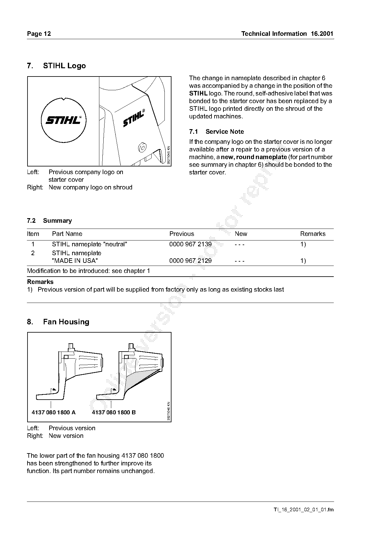
                                                                 The change in nameplate described in chapter 6
                                                                 was accompanied by a change in the position of the
                                                                 STIHL logo. The round, self-adhesive label that was
                                                                 bonded to the starter cover has been replaced by a
                                                                 STIHL logo printed directly on the shroud of the
                                                                 updated machines.

                                                                 7.1   Service Note
                                                                 If the company logo on the starter cover is no longer
                                                                 available after a repair to a previous version of a

                                                   392TI045 KN

                                                                 machine, a new, round nameplate (for part number

                                                                 see summary in chapter 6) should be bonded to the
Left:  Previous company logo on                                  starter cover.
       starter cover

Right: New company logo on shroud

7.2     Summary

Item      Part Name                                       Previous
                                                                         fo      New                      Remarks
 1        STIHL nameplate "neutral"                       0000 967 2139          ---                      1)
 2        STIHL nameplate
          "MADE IN USA"                                   0000 967 2129          ---                      1)

Modification to be introduced: see chapter 1
Remarks
1) Previous version of part will be supplied from factory only as long as existing stocks last

8.      Fan Housing

                                                   392TI046 KN

  4137 080 1800 A      4137 080 1800 B

Left: Previous version
Right: New version

The lower part of the fan housing 4137 080 1800
has been strengthened to further improve its
function. Its part number remains unchanged.

                                                                                                TI_16_2001_02_01_01.fm
Page 13 of 14
Text of page 13 — search, copy, screen readers
Technical Information 16.2001                                                                                     Page 13

Summary

Item     Part Name                                           Previous               New                      Remarks
 1       Fan housing                                         4137 080 1800          4137 080 1800            1)
Modification to be introduced: see chapter 1
Remarks
1) Only modified version of part is available from factory

9.     Lightweight Shaft (FS 85)
                                                                   As a result of the larger diameter of the lightweight

                                                                   shaft, this model will feature a new bearing tube
                                                                   (previous part name: "flexible liner“) from the serial
                                                 1
                                                                   number mentioned in chapter 1.

                6 mm (0.236")

                                                 2
                                                                   9.1   Service Note
                                                                   The new drive shaft can only be installed in previous
                                                                   versions together with the new version of "flexible
                                                     392TI047 KN

           8 mm (0.315")                                           liner" (bearing tube).

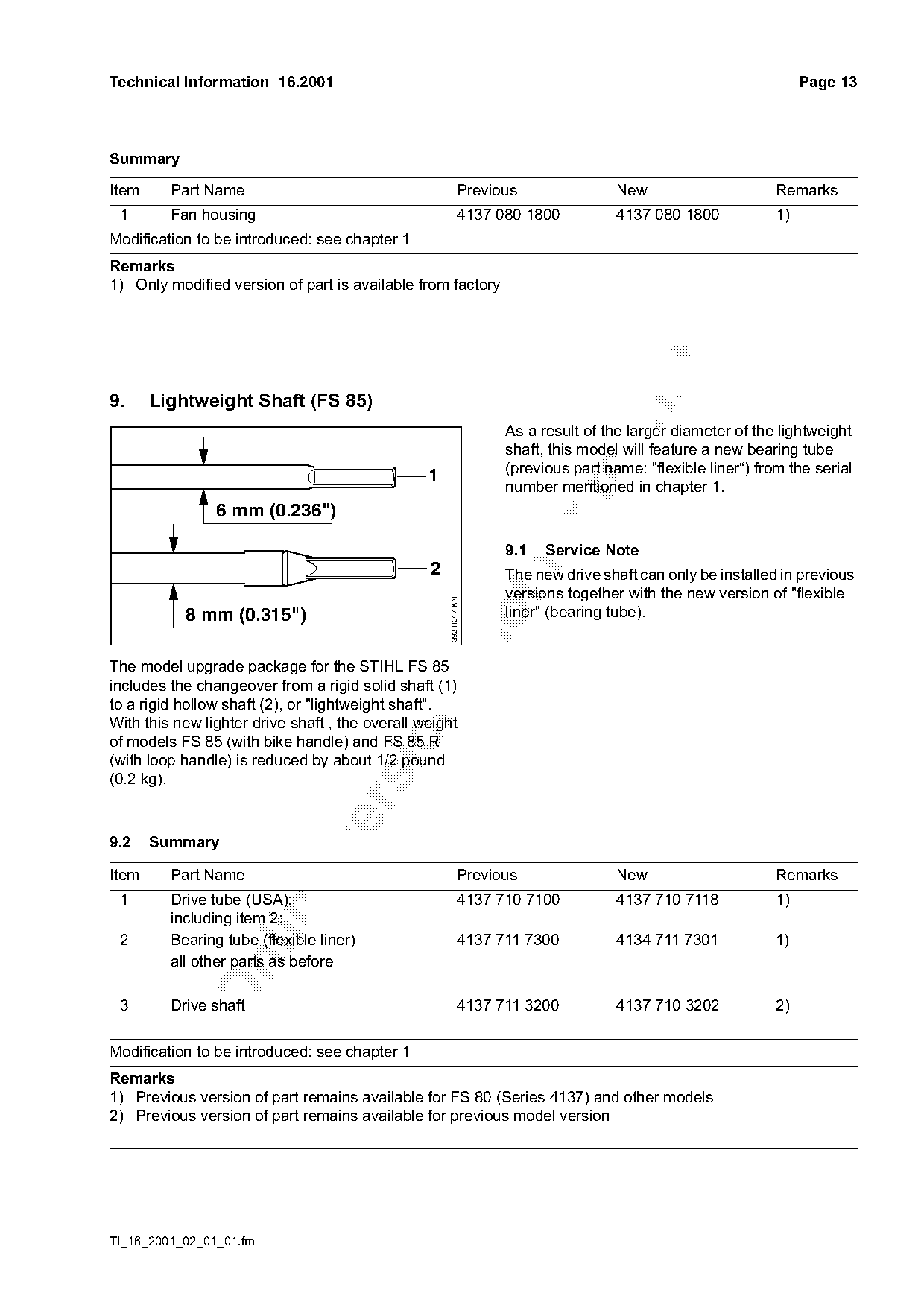
The model upgrade package for the STIHL FS 85
includes the changeover from a rigid solid shaft (1)
to a rigid hollow shaft (2), or "lightweight shaft".

With this new lighter drive shaft , the overall weight

of models FS 85 (with bike handle) and FS 85 R
(with loop handle) is reduced by about 1/2 pound
(0.2 kg).

9.2    Summary

Item     Part Name                                           Previous               New                      Remarks
 1       Drive tube (USA):                                   4137 710 7100          4137 710 7118            1)

         including item 2:
 2       Bearing tube (flexible liner)                       4137 711 7300          4134 711 7301            1)
         all other parts as before

 3       Drive shaft                                         4137 711 3200          4137 710 3202            2)

Modification to be introduced: see chapter 1
Remarks
1) Previous version of part remains available for FS 80 (Series 4137) and other models
2) Previous version of part remains available for previous model version

TI_16_2001_02_01_01.fm
Page 14 of 14
Text of page 14 — search, copy, screen readers
Page 14                                                                   Technical Information 16.2001

10. Lubricating the Drive Shaft
In the service workshop it is necessary to lubricate
or relubricate the drive shaft after performing repairs
in the area of the drive tube.
Important:
STIHL recommends using only STIHL gear
lubricant for hedge trimmers when lubricating the
drive shaft and internal bore of the bearing tube
(flexible liner).

Available sizes

– 3 oz (80 g) tube                   0781 120 1109
– 8 oz (225 g) tube                  0781 120 1110

© 2001 Andreas Stihl AG & Co.                             Technical Documentation
  Waiblingen                                              D1/MTK-na                                 7280

                                                                                    TI_16_2001_02_01_01.fm
Most of these PDFs embed fonts with a shifted character map, so the text above was recovered rather than copied — read it as a faithful but imperfect transcription, and treat the page image above each block as the authority where the two disagree — the figures exist only there, because they are vector drawings that text extraction cannot keep.