Technical Information · issue 19 of 2001
Ignition Module; Crankcase; Fan Housing; Control H
Model BR / SR 320, 340, 400, 420 Blowers and Sprayers – Series 4203
IssueTI 19/2001
Part changes (1)
| Was | Becomes | What the bulletin says |
|---|---|---|
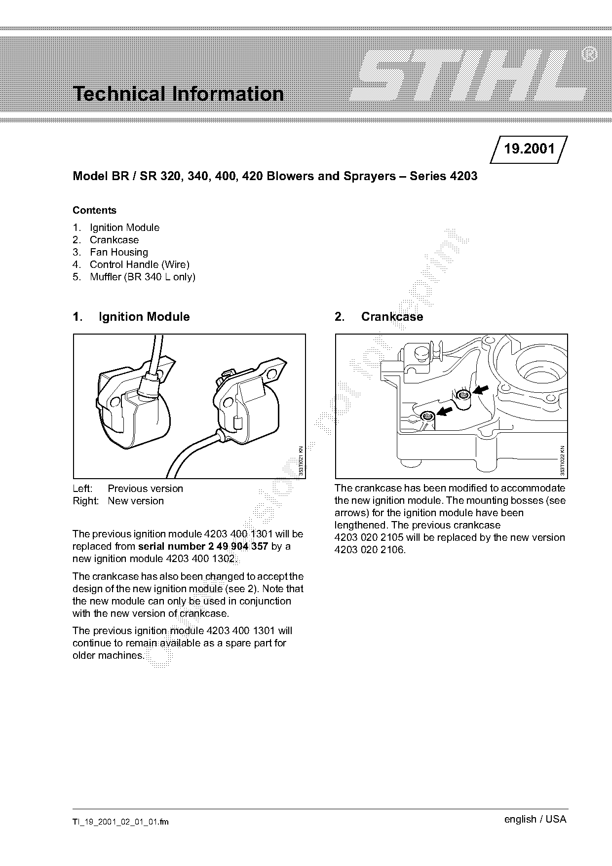
| 4203 400 1301 | 4203 020 2106 | The previous ignition module 4203 400 1301 will be 4203 020 2105 will be replaced by the new version replaced from serial number 2 49 904 357 by a 4203 020 2106. |
Full text
Page 1 of 3
Text of page 1 — search, copy, screen readers
Technical Information

                                                                                                    19.2001
Model BR / SR 320, 340, 400, 420 Blowers and Sprayers – Series 4203

Contents
1.   Ignition Module
2.   Crankcase

3.   Fan Housing

4.   Control Handle (Wire)
5.   Muffler (BR 340 L only)

1.    Ignition Module                                            2.   Crankcase

                                                                                                                353TI022 KN
                                                   353TI021 KN

Left: Previous version                                           The crankcase has been modified to accommodate

Right: New version                                               the new ignition module. The mounting bosses (see
                                                                 arrows) for the ignition module have been
                                                                 lengthened. The previous crankcase

The previous ignition module 4203 400 1301 will be               4203 020 2105 will be replaced by the new version
replaced from serial number 2 49 904 357 by a                    4203 020 2106.
new ignition module 4203 400 1302.

The crankcase has also been changed to accept the
design of the new ignition module (see 2). Note that
the new module can only be used in conjunction

with the new version of crankcase.
The previous ignition module 4203 400 1301 will

continue to remain available as a spare part for
older machines.

TI_19_2001_02_01_01.fm                                                                              english / USA
Page 2 of 3
Text of page 2 — search, copy, screen readers
Page 2                                                                                Technical Information 19.2001

                                                                    4.   Control Handle (Wire)

                                                                                                                       353TI025 KN
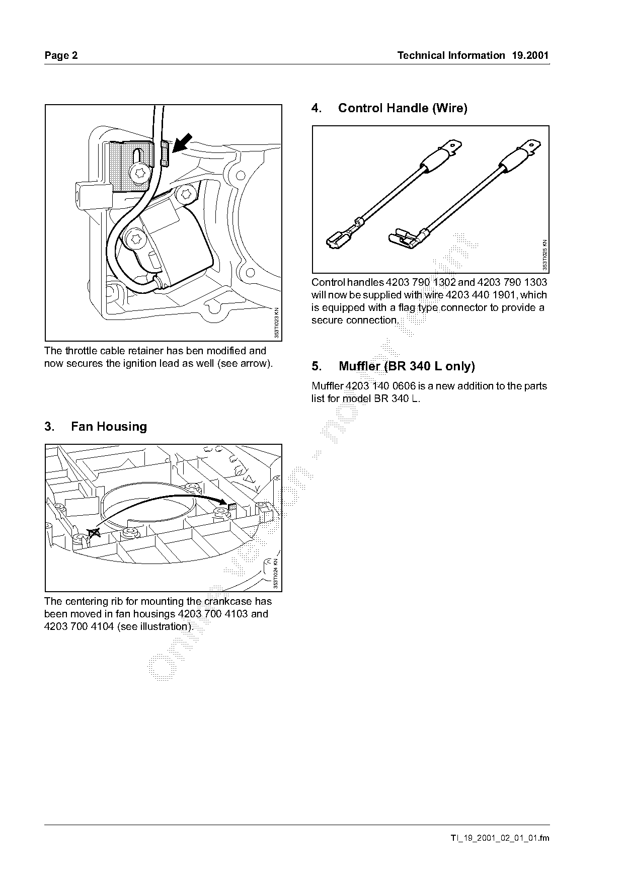
                                                                    Control handles 4203 790 1302 and 4203 790 1303
                                                                    will now be supplied with wire 4203 440 1901, which

                                                                    is equipped with a flag type connector to provide a
                                                      353TI023 KN

                                                                    secure connection.

The throttle cable retainer has ben modified and
now secures the ignition lead as well (see arrow).                  5.   Muffler (BR 340 L only)
                                                                    Muffler 4203 140 0606 is a new addition to the parts
                                                                    list for model BR 340 L.

3.   Fan Housing
                                                     353TI024 KN

The centering rib for mounting the crankcase has
been moved in fan housings 4203 700 4103 and

4203 700 4104 (see illustration).

                                                                                                  TI_19_2001_02_01_01.fm
Page 3 of 3
Text of page 3 — search, copy, screen readers
Technical Information 19.2001                                                                Page 3

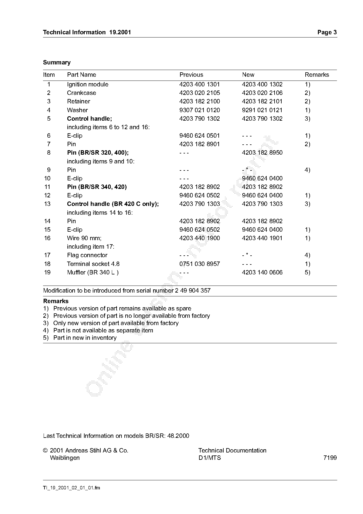
Summary

Item     Part Name                                 Previous             New             Remarks
 1       Ignition module                           4203 400 1301        4203 400 1302   1)
 2       Crankcase                                 4203 020 2105        4203 020 2106   2)
 3       Retainer                                  4203 182 2100        4203 182 2101   2)
 4       Washer                                    9307 021 0120        9291 021 0121   1)
 5       Control handle;                           4203 790 1302        4203 790 1302   3)
         including items 6 to 12 and 16:
 6       E-clip                                    9460 624 0501        ---             1)
 7       Pin                                       4203 182 8901        ---             2)

 8       Pin (BR/SR 320, 400);                     ---                  4203 182 8950
         including items 9 and 10:
 9       Pin                                       ---                  -*-             4)

10       E-clip                                    ---                  9460 624 0400
11       Pin (BR/SR 340, 420)                      4203 182 8902        4203 182 8902

12       E-clip                                    9460 624 0502        9460 624 0400   1)
13       Control handle (BR 420 C only);           4203 790 1303        4203 790 1303   3)
         including items 14 to 16:
14       Pin
                                                   4203 182 8902        4203 182 8902
15       E-clip                                    9460 624 0502        9460 624 0400   1)
16       Wire 90 mm;                               4203 440 1900        4203 440 1901   1)
         including item 17:

17       Flag connector                            ---                  -*-             4)
18       Terminal socket 4.8                       0751 030 8957        ---             1)
19       Muffler (BR 340 L )                       ---                  4203 140 0606   5)

Modification to be introduced from serial number 2 49 904 357
Remarks
1) Previous version of part remains available as spare
2) Previous version of part is no longer available from factory

3) Only new version of part available from factory
4) Part is not available as separate item

5) Part in new in inventory

Last Technical Information on models BR/SR: 48.2000

© 2001 Andreas Stihl AG & Co.                             Technical Documentation
  Waiblingen                                              D1/MTS                              7199

TI_19_2001_02_01_01.fm
Most of these PDFs embed fonts with a shifted character map, so the text above was recovered rather than copied — read it as a faithful but imperfect transcription, and treat the page image above each block as the authority where the two disagree — the figures exist only there, because they are vector drawings that text extraction cannot keep.