Technical Information · issue 22 of 2001
Model Update; Reinforced Drive Tube; Carburetor Mo
Model BT 120 C Earth Auger – Series 4313
IssueTI 22/2001
Part changes (3)
| Was | Becomes | What the bulletin says |
|---|---|---|
| 4134 190 0600 | 4134 190 0601 | 1 Scope of Modification The previous rewind spring 4134 190 0600 (1) will be replaced by the new version 4134 190 0601 (2) with an enclosed spring housing, which is mounted in the fan housing with two screws. |
| 4134 080 1800 | 4134 080 1801 | 1 Fan Housing / Spring Housing 5 The fan housing 4134 080 1800 has been replaced by the new version 4134 080 1801 to accommodate Previous and new versions of the fan housing and the spring housing. |
| 4134 400 1306 | 4134 400 1301 | The previous ignition module 4134 400 1306 will be replaced by the new version 4134 400 1301. |
Full text
Page 1 of 12
Text of page 1 — search, copy, screen readers
Technical Information

                                                                                            22.2001
Model BT 120 C Earth Auger                                                – Series 4313
Model FS 120, FS 200 Clearing Saws                                        – Series 4134
Model FS 350 Clearing Saw                                                 – Series 4134

Contents
1. Model Update

2. Reinforced Drive Tube
3. Carburetor Mounting
    (Carburetor Housing, Cylinder)

4. Carburetor
    (Idle Speed Screw)
5. Rewind Starter / Fan Housing
    5.1 Scope of Modification
    5.2 Service Notes
    5.3 Summary
6. Model Plates on Shroud
7. Ignition Module

8. Muffler
9. Clutch Shroud (FS 120, FS 200)
10. Clutch Housing (FS 350)

11. Throttle Cable Retainer

1.   Model Update

The modifications described here are part of a        In some cases the modifications involve several
complex model update package and are being            assemblies and are interrelated in functional terms.
implemented in conjunction with the introduction of   Appropriate references are given in such cases.

the new FS 250.                                       Example: The modification to the fan housing is
All the new parts in the modifications described      connected to the rewind starter and re-positioning of
below have been, with a few exceptions, included in   the model plates.
the new FS 250 since the start of production.

TI_22_2001_02_01_01.fm                                                                      english / USA
Page 2 of 12
Text of page 2 — search, copy, screen readers
Page 2                                                                                 Technical Information 22.2001

2.     Reinforced Drive Tube
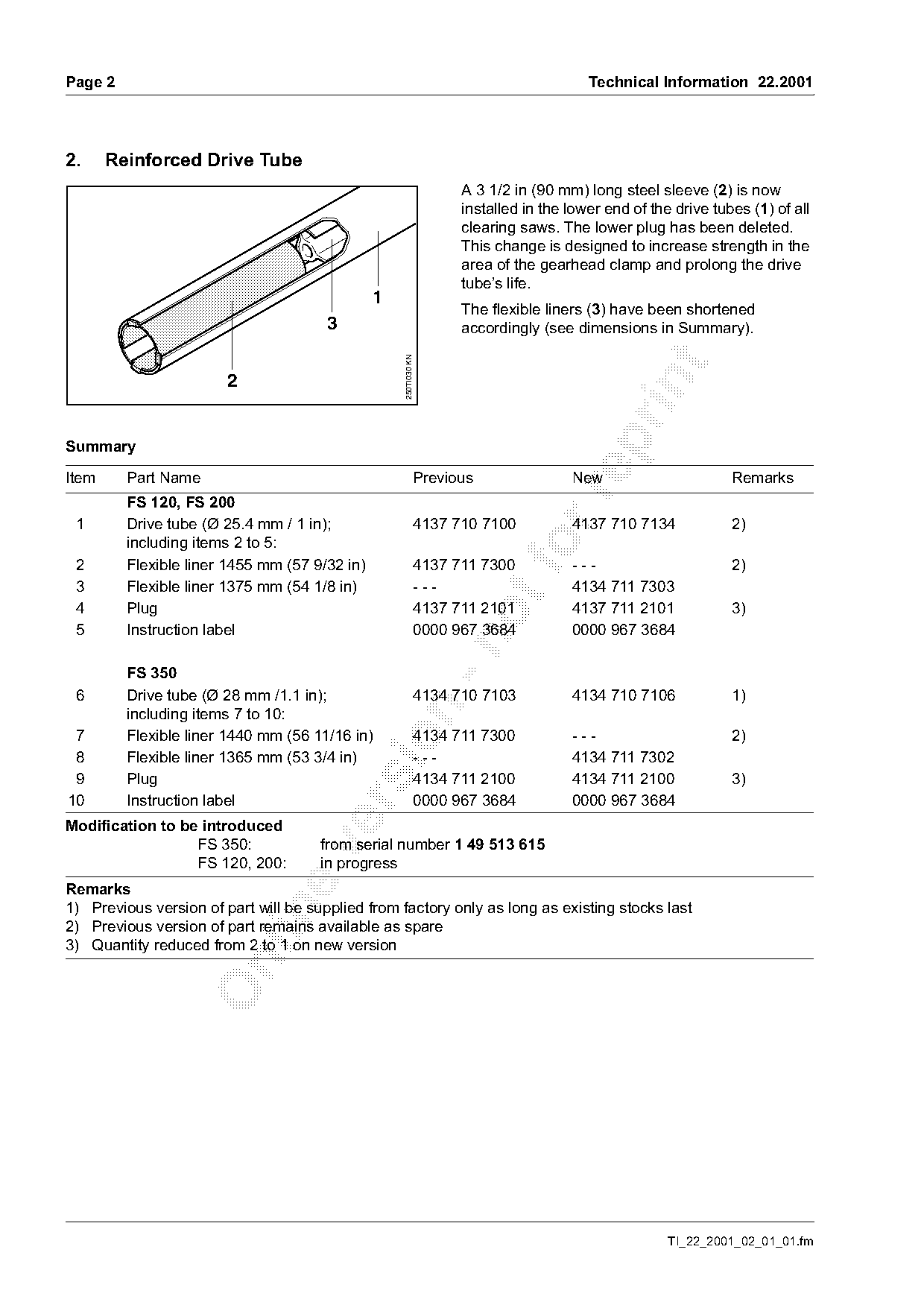
                                                                   A 3 1/2 in (90 mm) long steel sleeve (2) is now
                                                                   installed in the lower end of the drive tubes (1) of all
                                                                   clearing saws. The lower plug has been deleted.
                                                                   This change is designed to increase strength in the
                                                                   area of the gearhead clamp and prolong the drive
                                                                   tube’s life.
                                               1
                                                                   The flexible liners (3) have been shortened
                                       3                           accordingly (see dimensions in Summary).

                                                   250TI030 KN


Summary

Item     Part Name                                           Previous               New                       Remarks

         FS 120, FS 200
 1       Drive tube (Ø 25.4 mm / 1 in);                      4137 710 7100          4137 710 7134             2)
         including items 2 to 5:                                           fo
 2       Flexible liner 1455 mm (57 9/32 in)                 4137 711 7300          ---                       2)
 3       Flexible liner 1375 mm (54 1/8 in)                  ---                    4134 711 7303
 4       Plug                                                4137 711 2101          4137 711 2101             3)
 5       Instruction label                                   0000 967 3684          0000 967 3684

         FS 350
 6       Drive tube (Ø 28 mm /1.1 in);                       4134 710 7103          4134 710 7106             1)

         including items 7 to 10:
 7       Flexible liner 1440 mm (56 11/16 in)                4134 711 7300          ---                       2)

 8       Flexible liner 1365 mm (53 3/4 in)                  ---                    4134 711 7302
 9       Plug                                                4134 711 2100          4134 711 2100             3)
10       Instruction label                                   0000 967 3684          0000 967 3684

Modification to be introduced
                  FS 350:             from serial number 1 49 513 615

                  FS 120, 200:        in progress
Remarks
1) Previous version of part will be supplied from factory only as long as existing stocks last

2) Previous version of part remains available as spare
3) Quantity reduced from 2 to 1 on new version

                                                                                                    TI_22_2001_02_01_01.fm
Page 3 of 12
Text of page 3 — search, copy, screen readers
Technical Information 22.2001                                                                                   Page 3

3.     Carburetor Mounting
       (Carburetor Housing, Cylinder)
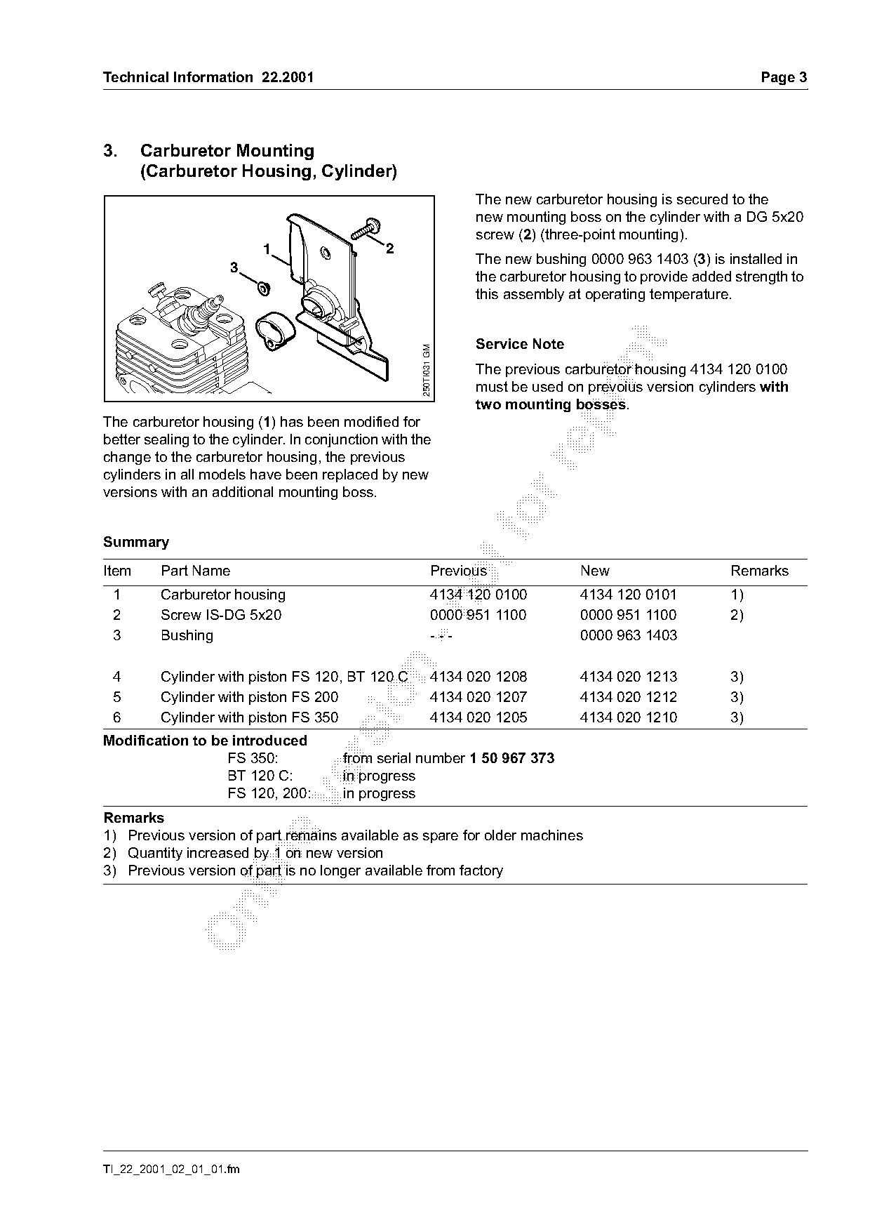
                                                                    The new carburetor housing is secured to the
                                                                    new mounting boss on the cylinder with a DG 5x20
                                                                    screw (2) (three-point mounting).
                          1                    2
                                                                    The new bushing 0000 963 1403 (3) is installed in
                     3
                                                                    the carburetor housing to provide added strength to
                                                                    this assembly at operating temperature.

                                                                    Service Note

                                                     250TI031 GM

                                                                    The previous carburetor housing 4134 120 0100
                                                                    must be used on prevoius version cylinders with
                                                                    two mounting bosses.

The carburetor housing (1) has been modified for
better sealing to the cylinder. In conjunction with the
change to the carburetor housing, the previous

cylinders in all models have been replaced by new
versions with an additional mounting boss.

Summary
Item     Part Name                                            Previous              New                    Remarks
 1       Carburetor housing                                   4134 120 0100         4134 120 0101          1)

 2       Screw IS-DG 5x20                                     0000 951 1100         0000 951 1100          2)
 3       Bushing                                              ---                   0000 963 1403

 4       Cylinder with piston FS 120, BT 120 C                4134 020 1208         4134 020 1213          3)

 5       Cylinder with piston FS 200                          4134 020 1207         4134 020 1212          3)
 6       Cylinder with piston FS 350                          4134 020 1205         4134 020 1210          3)
Modification to be introduced

                  FS 350:               from serial number 1 50 967 373
                  BT 120 C:             in progress
                  FS 120, 200:          in progress

Remarks
1) Previous version of part remains available as spare for older machines
2) Quantity increased by 1 on new version

3) Previous version of part is no longer available from factory

TI_22_2001_02_01_01.fm
Page 4 of 12
Text of page 4 — search, copy, screen readers
Page 4                                                                            Technical Information 22.2001

4.       Carburetor
         (Idle Speed Screw)
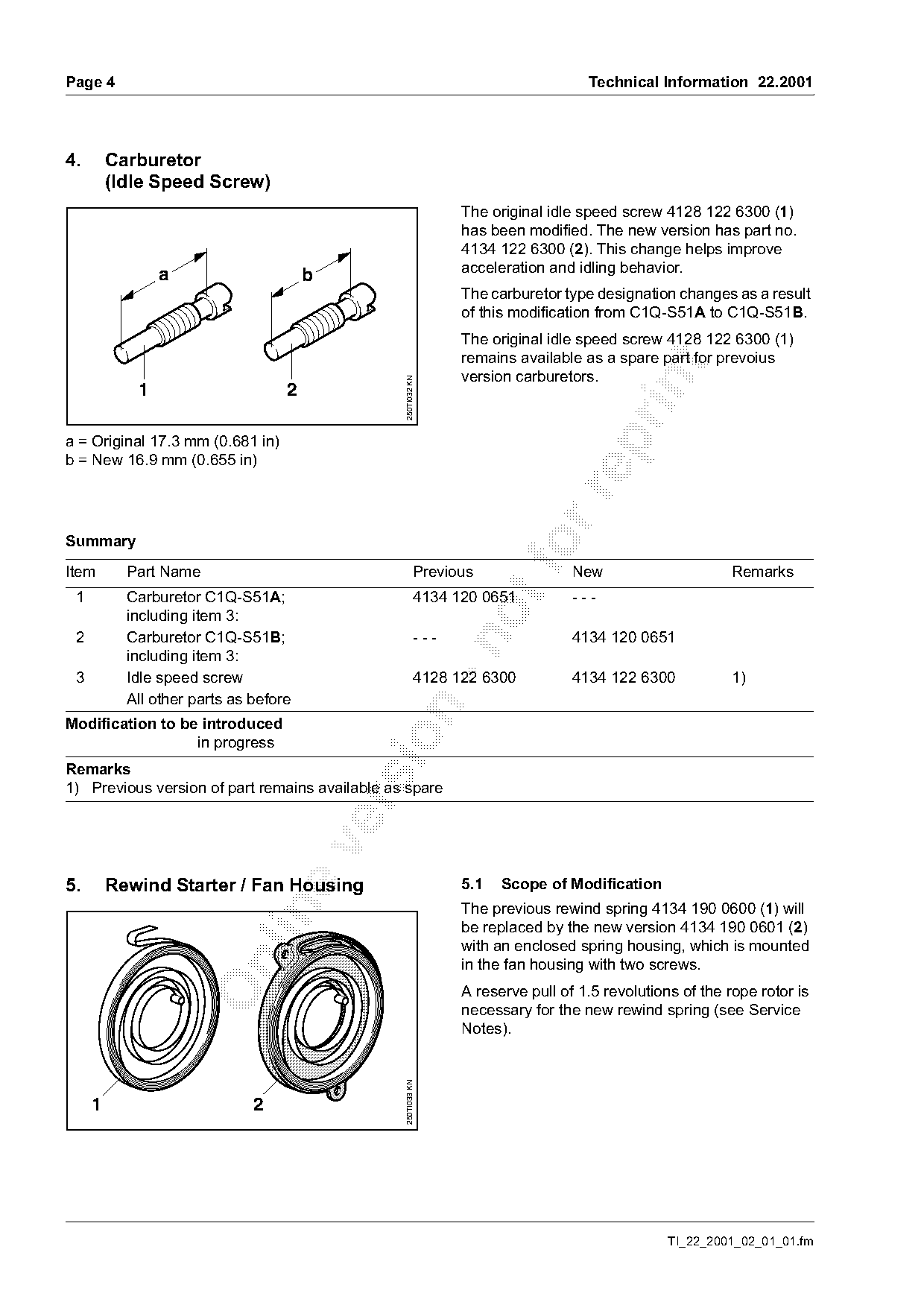
                                                               The original idle speed screw 4128 122 6300 (1)
                                                               has been modified. The new version has part no.
                                                               4134 122 6300 (2). This change helps improve
                a                                              acceleration and idling behavior.
                                       b
                                                               The carburetor type designation changes as a result
                                                               of this modification from C1Q-S51A to C1Q-S51B.
                                                               The original idle speed screw 4128 122 6300 (1)
                                                               remains available as a spare part for prevoius

                                                               version carburetors.

                                                250TI032 KN
            1                      2

a = Original 17.3 mm (0.681 in)

b = New 16.9 mm (0.655 in)

Summary

Item       Part Name                                     Previous
                                                                       fo       New                     Remarks
 1         Carburetor C1Q-S51A;                          4134 120 0651          ---
           including item 3:
 2         Carburetor C1Q-S51B;                          ---                    4134 120 0651

           including item 3:
 3         Idle speed screw                              4128 122 6300          4134 122 6300            1)
           All other parts as before

Modification to be introduced

                  in progress
Remarks
1) Previous version of part remains available as spare

5.       Rewind Starter / Fan Housing                          5.1   Scope of Modification
                                                               The previous rewind spring 4134 190 0600 (1) will

                                                               be replaced by the new version 4134 190 0601 (2)
                                                               with an enclosed spring housing, which is mounted

                                                               in the fan housing with two screws.
                                                               A reserve pull of 1.5 revolutions of the rope rotor is
                                                               necessary for the new rewind spring (see Service
                                                               Notes).
                                                250TI033 KN

     1                        2

                                                                                               TI_22_2001_02_01_01.fm
Page 5 of 12
Text of page 5 — search, copy, screen readers
Technical Information 22.2001                                                                                 Page 5

                                                                 5.2   Service Notes

                                                                 5.2.1 Fan Housing


                                                   250TI034 KN
                                                                   4

                                                                                                                    250TI035 KN
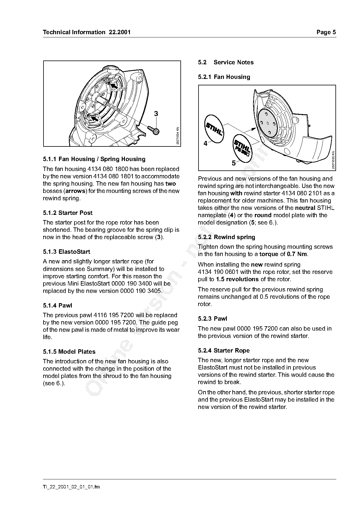
5.1.1 Fan Housing / Spring Housing
                                                                              5
The fan housing 4134 080 1800 has been replaced

by the new version 4134 080 1801 to accommodate                  Previous and new versions of the fan housing and
the spring housing. The new fan housing has two                  rewind spring are not interchangeable. Use the new
bosses (arrows) for the mounting screws of the new               fan housing with rewind starter 4134 080 2101 as a

rewind spring.                                                   replacement for older machines. This fan housing
                                                                 takes either the new versions of the neutral STIHL
5.1.2 Starter Post                                                fo
                                                                 nameplate (4) or the round model plate with the
The starter post for the rope rotor has been                     model designation (5; see 6.).
shortened. The bearing groove for the spring clip is
now in the head of the replaceable screw (3).                    5.2.2 Rewind spring
                                                                 Tighten down the spring housing mounting screws
5.1.3 ElastoStart

                                                                 in the fan housing to a torque of 0.7 Nm.
A new and slightly longer starter rope (for
                                                                 When installing the new rewind spring
dimensions see Summary) will be installed to                     4134 190 0601 with the rope rotor, set the reserve
improve starting comfort. For this reason the

                                                                 pull to 1.5 revolutions of the rotor.
previous Mini ElastoStart 0000 190 3400 will be
                                                                 The reserve pull for the previous rewind spring

replaced by the new version 0000 190 3405.
                                                                 remains unchanged at 0.5 revolutions of the rope
5.1.4 Pawl                                                       rotor.
The previous pawl 4116 195 7200 will be replaced

                                                                 5.2.3 Pawl
by the new version 0000 195 7200. The guide peg
of the new pawl is made of metal to improve its wear             The new pawl 0000 195 7200 can also be used in

life.                                                            the previous version of the rewind starter.

5.1.5 Model Plates                                               5.2.4 Starter Rope

The introduction of the new fan housing is also                  The new, longer starter rope and the new
connected with the change in the position of the                 ElastoStart must not be installed in previous
model plates from the shroud to the fan housing                  versions of the rewind starter. This would cause the

(see 6.).                                                        rewind to break.
                                                                 On the other hand, the previous, shorter starter rope
                                                                 and the previous ElastoStart may be installed in the
                                                                 new version of the rewind starter.

TI_22_2001_02_01_01.fm
Page 6 of 12
Text of page 6 — search, copy, screen readers
Page 6                                                                        Technical Information 22.2001

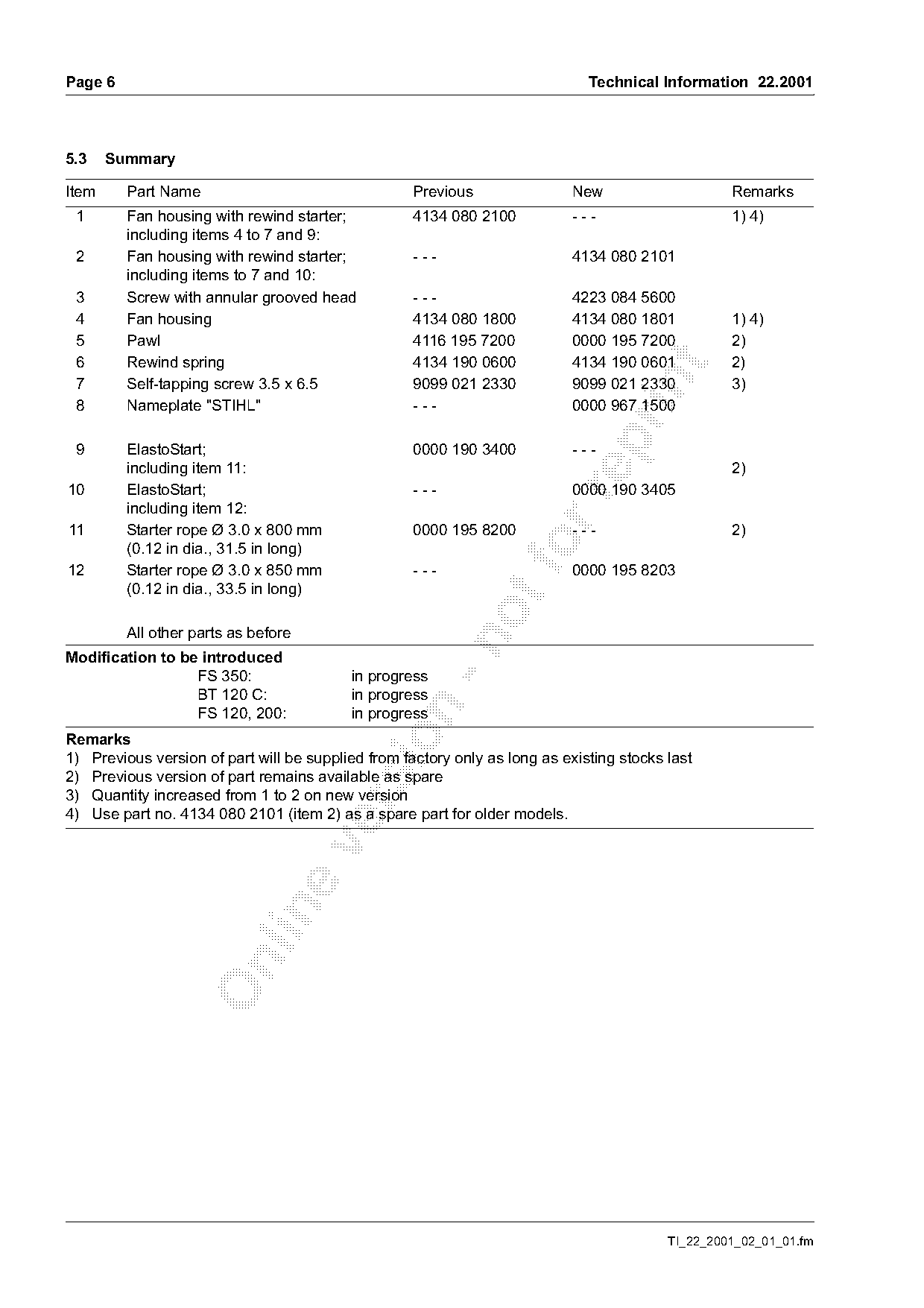
5.3    Summary

Item     Part Name                                  Previous                New                    Remarks
 1       Fan housing with rewind starter;           4134 080 2100           ---                    1) 4)
         including items 4 to 7 and 9:
 2       Fan housing with rewind starter;           ---                     4134 080 2101
         including items to 7 and 10:
 3       Screw with annular grooved head            ---                     4223 084 5600
 4       Fan housing                                4134 080 1800           4134 080 1801          1) 4)
 5       Pawl                                       4116 195 7200           0000 195 7200          2)
 6       Rewind spring                              4134 190 0600           4134 190 0601          2)

 7       Self-tapping screw 3.5 x 6.5               9099 021 2330           9099 021 2330          3)
 8       Nameplate "STIHL"                          ---                     0000 967 1500

 9       ElastoStart;                               0000 190 3400           ---
         including item 11:                                                                        2)
10       ElastoStart;                               ---                     0000 190 3405

         including item 12:
11       Starter rope Ø 3.0 x 800 mm                0000 195 8200           ---                    2)

12
         (0.12 in dia., 31.5 in long)
         Starter rope Ø 3.0 x 850 mm                ---
                                                                   fo       0000 195 8203
         (0.12 in dia., 33.5 in long)

         All other parts as before

Modification to be introduced
                  FS 350:                 in progress
                  BT 120 C:               in progress

                  FS 120, 200:            in progress

Remarks
1) Previous version of part will be supplied from factory only as long as existing stocks last
2) Previous version of part remains available as spare
3) Quantity increased from 1 to 2 on new version

4) Use part no. 4134 080 2101 (item 2) as a spare part for older models.

                                                                                          TI_22_2001_02_01_01.fm
Page 7 of 12
Text of page 7 — search, copy, screen readers
Technical Information 22.2001                                                                                       Page 7

6.      Model Plates on Shroud                                     Service Note


                                                     250TI036 KN

                                                                                                   2
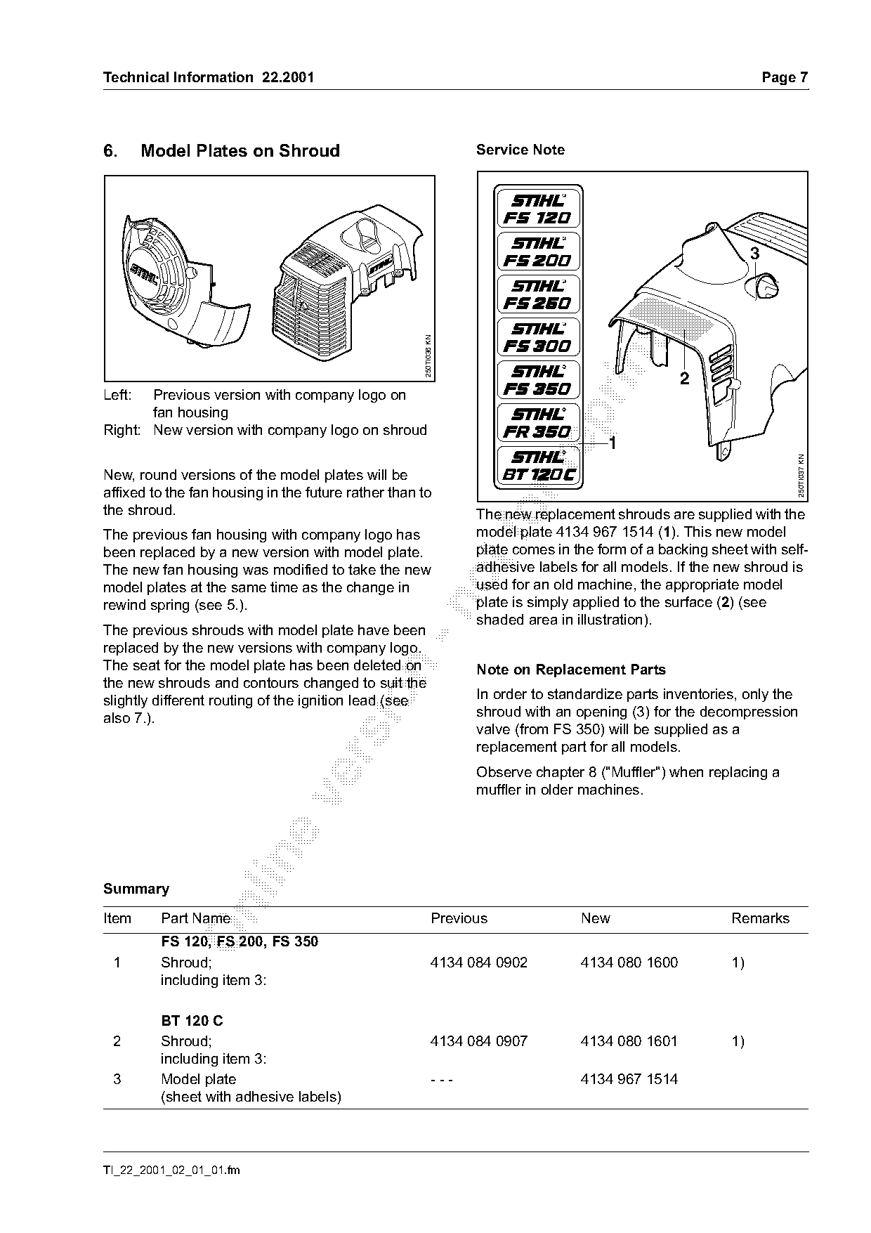
Left:  Previous version with company logo on
       fan housing

Right: New version with company logo on shroud
                                                                                        1

                                                                                                                        250TI037 KN
New, round versions of the model plates will be
affixed to the fan housing in the future rather than to
the shroud.
The previous fan housing with company logo has
                                                                   The new replacement shrouds are supplied with the
                                                                   model plate 4134 967 1514 (1). This new model
been replaced by a new version with model plate.                   plate comes in the form of a backing sheet with self-
The new fan housing was modified to take the new                   adhesive labels for all models. If the new shroud is
model plates at the same time as the change in                     used for an old machine, the appropriate model
rewind spring (see 5.).                                            plate is simply applied to the surface (2) (see

                                                                   shaded area in illustration).
The previous shrouds with model plate have been
replaced by the new versions with company logo.
The seat for the model plate has been deleted on                   Note on Replacement Parts

the new shrouds and contours changed to suit the
                                                                   In order to standardize parts inventories, only the

slightly different routing of the ignition lead (see
also 7.).                                                          shroud with an opening (3) for the decompression
                                                                   valve (from FS 350) will be supplied as a
                                                                   replacement part for all models.

                                                                   Observe chapter 8 ("Muffler") when replacing a
                                                                   muffler in older machines.

Summary

Item      Part Name                                          Previous              New                     Remarks
          FS 120, FS 200, FS 350
 1        Shroud;                                            4134 084 0902         4134 080 1600           1)
          including item 3:

          BT 120 C
 2        Shroud;                                            4134 084 0907         4134 080 1601           1)
          including item 3:
 3        Model plate                                        ---                   4134 967 1514
          (sheet with adhesive labels)

TI_22_2001_02_01_01.fm
Page 8 of 12
Text of page 8 — search, copy, screen readers
Page 8                                                                                Technical Information 22.2001

Item     Part Name                                           Previous              New                     Remarks
 4       Model plate FS 120                                  4134 967 1503         4134 967 1511           2)
 5       Model plate FS 200                                  4134 967 1502         4134 967 1510           2)
 7       Model plate FS 350                                  4134 967 1500         4134 967 1507           2)
 9       Model plate BT 120 C                                4313 967 1500         4313 967 1501           2)
Modification to be introduced: see Summary 5.3
Remarks
1) Previous version of part is no longer available from factory
2) Previous version of part will be supplied from factory only as long as existing stocks last

7.     Ignition Module

                     XXXX XXXX X

                                     4134 1301 A
                                                   250TI038 KN

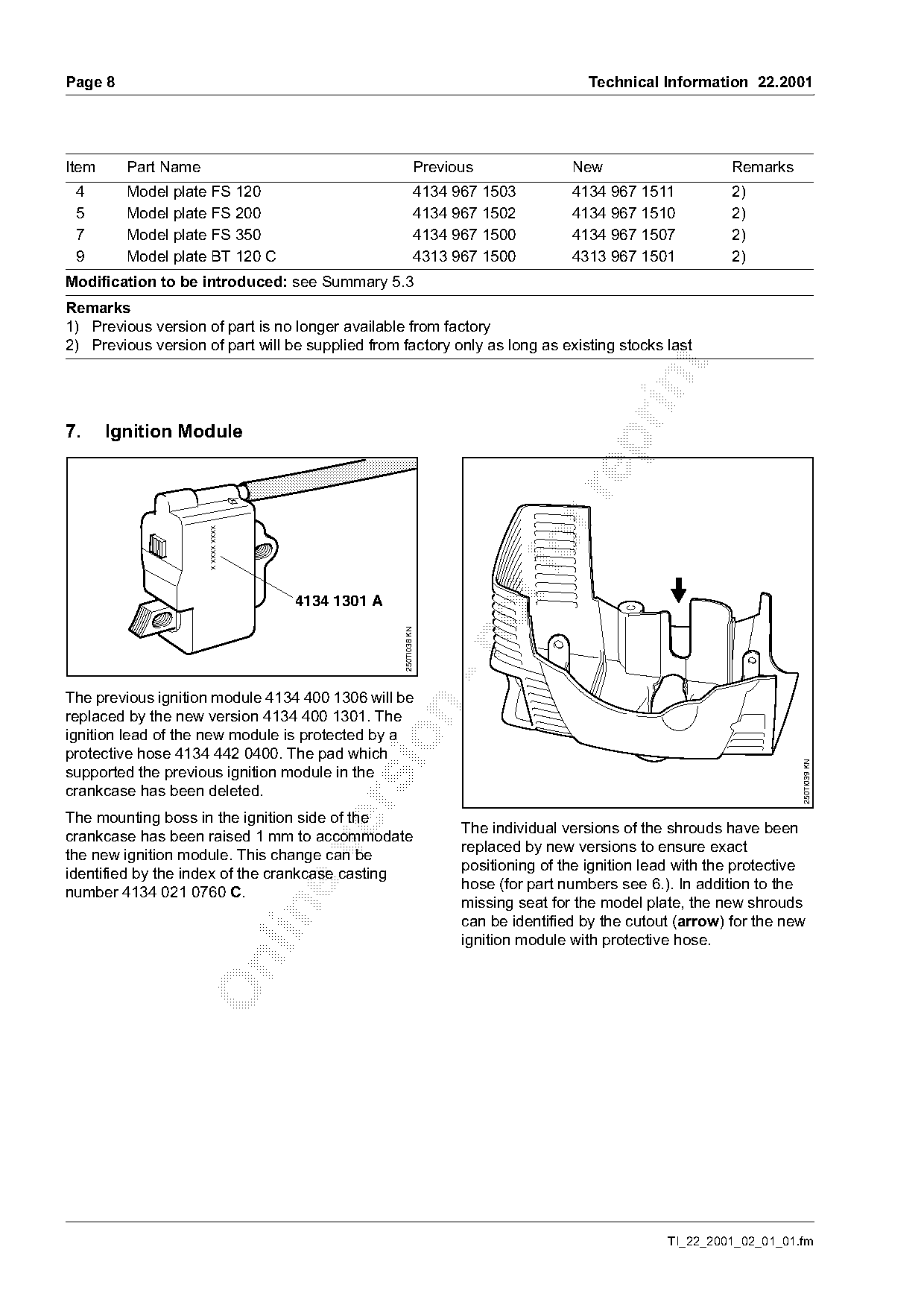
The previous ignition module 4134 400 1306 will be

replaced by the new version 4134 400 1301. The
ignition lead of the new module is protected by a

protective hose 4134 442 0400. The pad which

                                                                                                                      250TI039 KN
supported the previous ignition module in the
crankcase has been deleted.

The mounting boss in the ignition side of the
crankcase has been raised 1 mm to accommodate                      The individual versions of the shrouds have been
                                                                   replaced by new versions to ensure exact

the new ignition module. This change can be
identified by the index of the crankcase casting                   positioning of the ignition lead with the protective
number 4134 021 0760 C.                                            hose (for part numbers see 6.). In addition to the
                                                                   missing seat for the model plate, the new shrouds

                                                                   can be identified by the cutout (arrow) for the new
                                                                   ignition module with protective hose.

                                                                                                  TI_22_2001_02_01_01.fm
Page 9 of 12
Text of page 9 — search, copy, screen readers
Technical Information 22.2001                                                                        Page 9

Service Note
When installing a previous version of the crankcase     The new ignition module may only be installed
(casting number 4134 021 0760), in combination          together with new shrouds (see chapter 6 and
with the new ignition module, place an A 5.3 washer     service note chapter 9).
between the mounting boss and core stack at both
mounting points. An A 5.3 washer must also be
assembled under the screw heads in all cases.

Summary
Item     Part Name                                Previous              New                     Remarks

 1       Ignition module;                         4134 400 1306         ---                     1)
         including items 4 and 5:
 2       Ignition module;                         ---                   4134 400 1301

         including items 3 to 5:
 3       Protective hose                          ---                   4137 442 0400
 4
 5
         Spark plug boot
         Leg spring
                                                  4128 405 1000
                                                  0000 998 0604
                                                                        4128 405 1000
                                                                        0000 998 0604
 6       Pad                                      4134 028 1300         ---                     1)
 7       Washer A 5.3 (2x)                        ---                   9291 021 0121
Modification to be introduced: see Summary 5.3

Remarks
1) Previous version of part remains available as spare for older machines

8.     Muffler

The muffler with shroud sets will be replaced by        The new sets include a model plate 4134 967 1514.
new versions. The shroud included in the sets has       This new model plate comes in the form of a backing

been modified in connection with the change in the      sheet with self-adhesive labels for all models. If a
ignition module and the positioning of the model        new shroud is used for an old machine, the
plates (see 6. and 7.).                                 appropriate model plate is simply applied to the
                                                        shroud.

Summary

Item     Part Name                                Previous              New                     Remarks
         FS 120, 200, 350
 1       Muffler;                                 4134 140 0650         4134 140 0652           1)
         including item 2:
 2       Shroud;                                  4134 084 0902         4134 080 1600           1)
         including item 3:
 3       Model plate
         (sheet with adhesive labels)             ---                   4134 967 1514

TI_22_2001_02_01_01.fm
Page 10 of 12
Text of page 10 — search, copy, screen readers
Page 10                                                                               Technical Information 22.2001

Item      Part Name                                         Previous               New                      Remarks
          BT 120 C
 4        Muffler;                                           4134 140 0651         4134 140 0653            1
          including item 5:
 5        Shroud;                                            4134 084 0907         4134 080 1601            1
          including item 3:
Modification to be introduced: see Summary 5.3
Remarks
1) Previous version of part is no longer available from factory

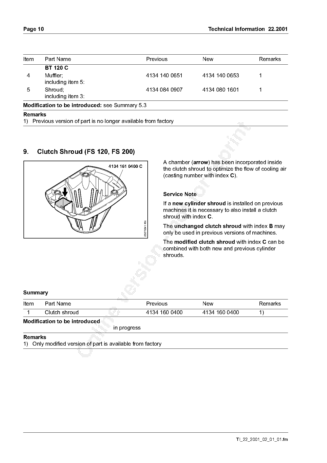
9.     Clutch Shroud (FS 120, FS 200)

                                                                   A chamber (arrow) has been incorporated inside
                                   4134 161 0400 C
                                                                   the clutch shroud to optimize the flow of cooling air

                                                                   (casting number with index C).
                                     xx
                                     xxx
                                      xx
                                          xx
                                           xxx

                                                                   Service Note
                                                                   If a new cylinder shroud is installed on previous
                                                                   machines it is necessary to also install a clutch
                                                                   shroud with index C.
                                                     250TI041 KN

                                                                   The unchanged clutch shroud with index B may

                                                                   only be used in previous versions of machines.
                                                                   The modified clutch shroud with index C can be
                                                                   combined with both new and previous cylinder

                                                                   shrouds.

Summary

Item      Part Name                                         Previous               New                      Remarks
 1        Clutch shroud                                      4134 160 0400         4134 160 0400            1)
Modification to be introduced

                                     in progress
Remarks

1) Only modified version of part is available from factory

                                                                                                  TI_22_2001_02_01_01.fm
Page 11 of 12
Text of page 11 — search, copy, screen readers
Technical Information 22.2001                                                                                          Page 11

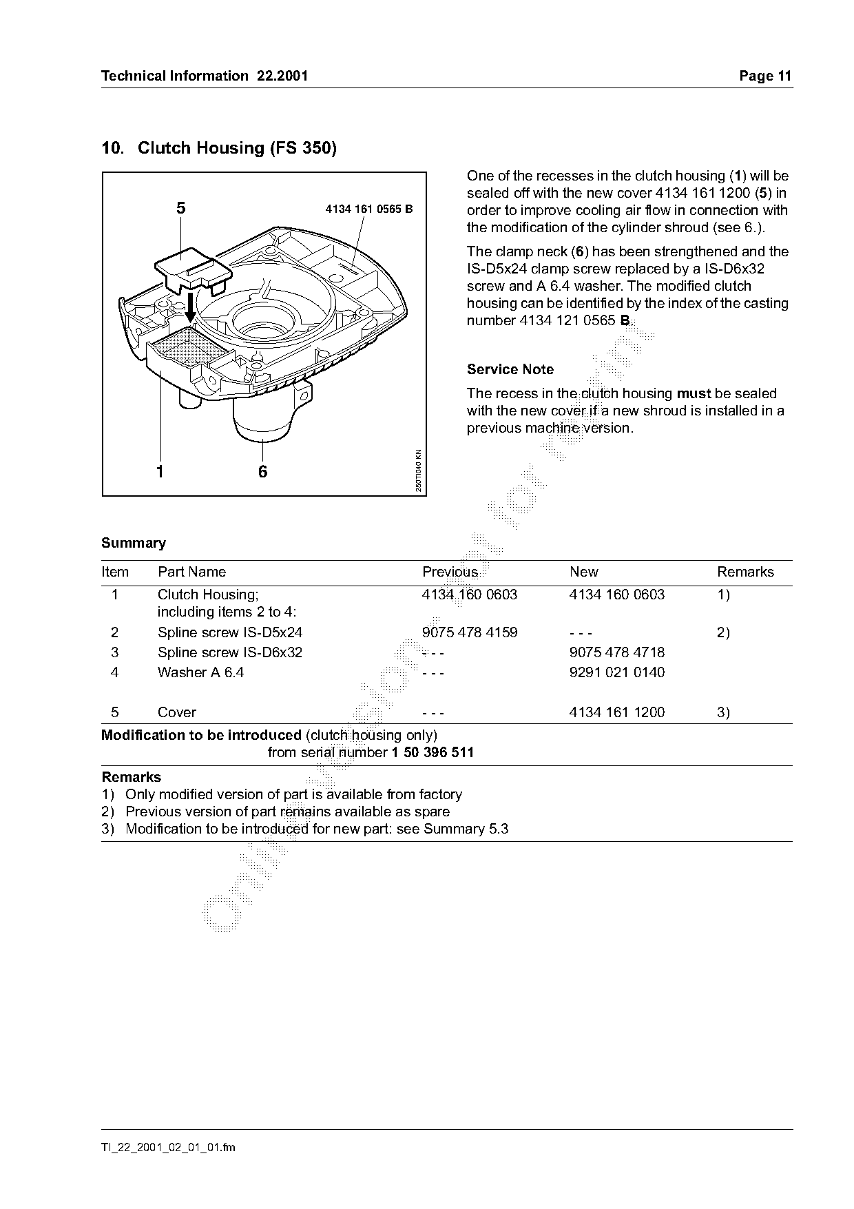
10. Clutch Housing (FS 350)
                                                                         One of the recesses in the clutch housing (1) will be
                                                                         sealed off with the new cover 4134 161 1200 (5) in
            5                      4134 161 0565 B                       order to improve cooling air flow in connection with
                                                                         the modification of the cylinder shroud (see 6.).
                                                                         The clamp neck (6) has been strengthened and the
                                                                         IS-D5x24 clamp screw replaced by a IS-D6x32
                                          x
                                     xxxx          xxx
                                              xxxx

                                                                         screw and A 6.4 washer. The modified clutch
                                                                         housing can be identified by the index of the casting
                                                                         number 4134 121 0565 B.

                                                                         Service Note
                                                                         The recess in the clutch housing must be sealed

                                                                         with the new cover if a new shroud is installed in a
                                                                         previous machine version.

                                                         250TI040 KN

        1                6

Summary
Item     Part Name                                                 Previous              New                      Remarks

 1       Clutch Housing;                                           4134 160 0603         4134 160 0603            1)
         including items 2 to 4:
 2       Spline screw IS-D5x24                                     9075 478 4159         ---                      2)
 3       Spline screw IS-D6x32                                     ---                   9075 478 4718

 4       Washer A 6.4                                              ---                   9291 021 0140

 5       Cover                                                     ---                   4134 161 1200            3)
Modification to be introduced (clutch housing only)

                         from serial number 1 50 396 511
Remarks

1) Only modified version of part is available from factory
2) Previous version of part remains available as spare
3) Modification to be introduced for new part: see Summary 5.3

TI_22_2001_02_01_01.fm
Page 12 of 12
Text of page 12 — search, copy, screen readers
Page 12                                                                             Technical Information 22.2001

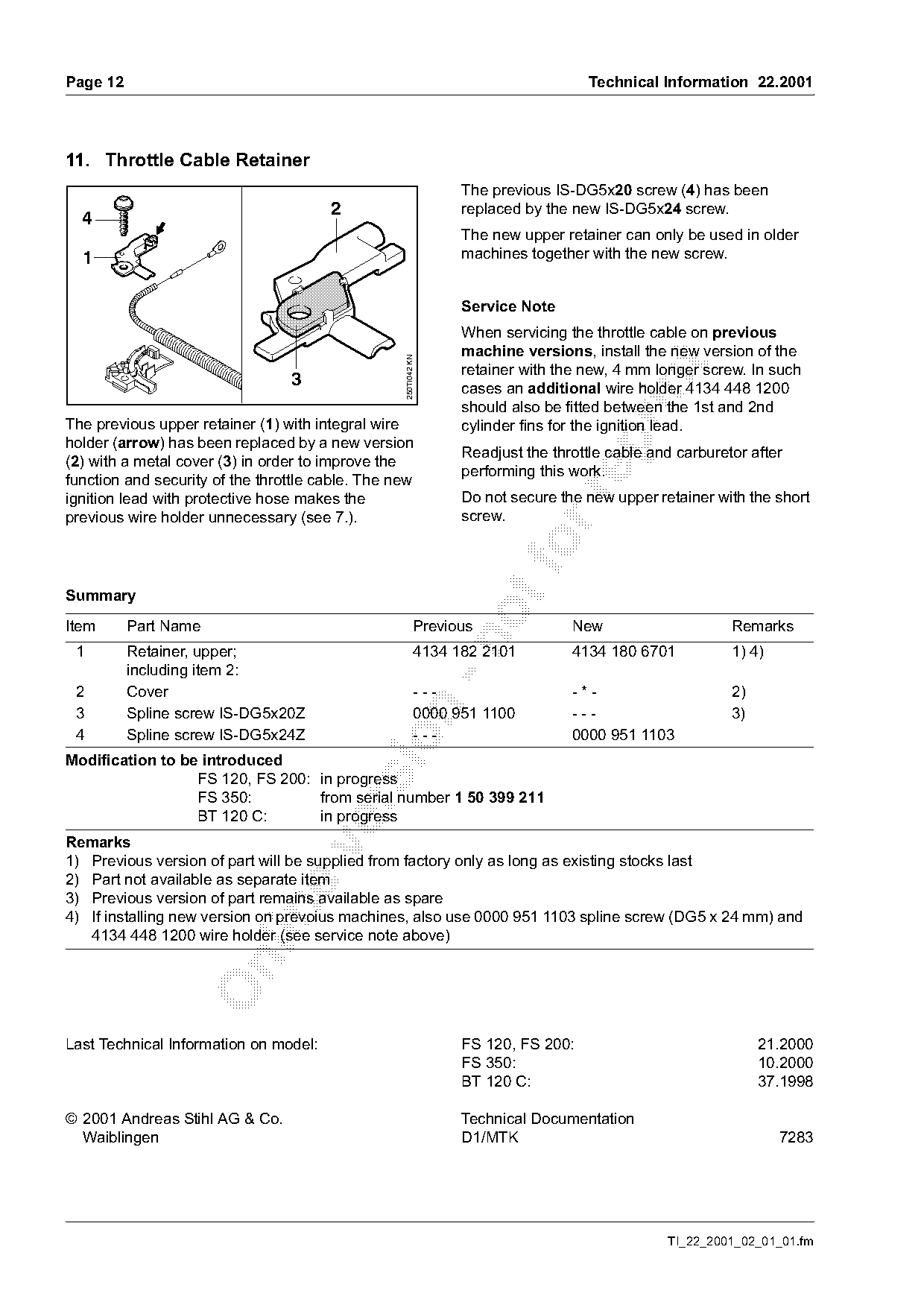
11. Throttle Cable Retainer
                                                                 The previous IS-DG5x20 screw (4) has been
                                       2                         replaced by the new IS-DG5x24 screw.
  4
                                                                 The new upper retainer can only be used in older
  1                                                              machines together with the new screw.

                                                                 Service Note
                                                                 When servicing the throttle cable on previous
                                                                 machine versions, install the new version of the

                                                  250TI042 KN

                                                                 retainer with the new, 4 mm longer screw. In such
                                 3

                                                                 cases an additional wire holder 4134 448 1200
                                                                 should also be fitted between the 1st and 2nd
The previous upper retainer (1) with integral wire               cylinder fins for the ignition lead.

holder (arrow) has been replaced by a new version
                                                                 Readjust the throttle cable and carburetor after
(2) with a metal cover (3) in order to improve the
                                                                 performing this work.
function and security of the throttle cable. The new

ignition lead with protective hose makes the                     Do not secure the new upper retainer with the short
previous wire holder unnecessary (see 7.).                       screw.

Summary

Item      Part Name                                        Previous              New                     Remarks

 1        Retainer, upper;                                 4134 182 2101         4134 180 6701           1) 4)
          including item 2:
 2        Cover                                            ---                   -*-                     2)

 3        Spline screw IS-DG5x20Z                          0000 951 1100         ---                     3)
 4        Spline screw IS-DG5x24Z                          ---                   0000 951 1103

Modification to be introduced
                  FS 120, FS 200: in progress
                  FS 350:         from serial number 1 50 399 211

                  BT 120 C:       in progress
Remarks

1) Previous version of part will be supplied from factory only as long as existing stocks last
2) Part not available as separate item
3) Previous version of part remains available as spare

4) If installing new version on prevoius machines, also use 0000 951 1103 spline screw (DG5 x 24 mm) and
   4134 448 1200 wire holder (see service note above)

Last Technical Information on model:                             FS 120, FS 200:                              21.2000
                                                                 FS 350:                                      10.2000
                                                                 BT 120 C:                                    37.1998

© 2001 Andreas Stihl AG & Co.                                    Technical Documentation
  Waiblingen                                                     D1/MTK                                          7283

                                                                                               TI_22_2001_02_01_01.fm
Most of these PDFs embed fonts with a shifted character map, so the text above was recovered rather than copied — read it as a faithful but imperfect transcription, and treat the page image above each block as the authority where the two disagree — the figures exist only there, because they are vector drawings that text extraction cannot keep.