Technical Information · issue 26 of 2001
Gearbox (Gasket); Handlebar with Hand Guard; Carbu
Model HS 45 Hedge Trimmers – Series 4228
IssueTI 26/2001
Part changes (3)
| Was | Becomes | What the bulletin says |
|---|---|---|
| 4228 791 0100 | 4228 791 0101 | Handlebar with Hand Guard The previous handlebar (front handle) with hand guard 4228 791 0100 will be replaced by a fully interchangeable version 4228 791 0101 in order to further optimize component strength. |
| 4140 121 1600 | 4140 121 1605 | The previous spacer flange 4140 121 1600 will be replaced by the new version 4140 121 1605 when the new carburetor is introduced (chapter 4. |
| 4140 182 7600 | 4140 182 7602 | LA The previous tensioner 4140 182 7600 will be replaced by tensioner 4140 182 7602. |
Full text
Page 1 of 7
Text of page 1 — search, copy, screen readers
Technical Information

                                                                                                    26.2001
Model HS 45 Hedge Trimmers – Series 4228

Contents
1. Gearbox (Gasket)
2. Handlebar with Hand Guard
3. Carburetor with LD Screw
   (Flange and End Cover Mounting)
4. Model Update Package
   4.1 Carburetor with 3 Adjusting Screws
   4.2 Spacer Flange, Tensioner
   4.3 Filter Housing (Choke Shutter), Filter Cover
   4.4 Ignition Module, Crankshaft
   4.5 Summary

1.     Gearbox (Gasket)
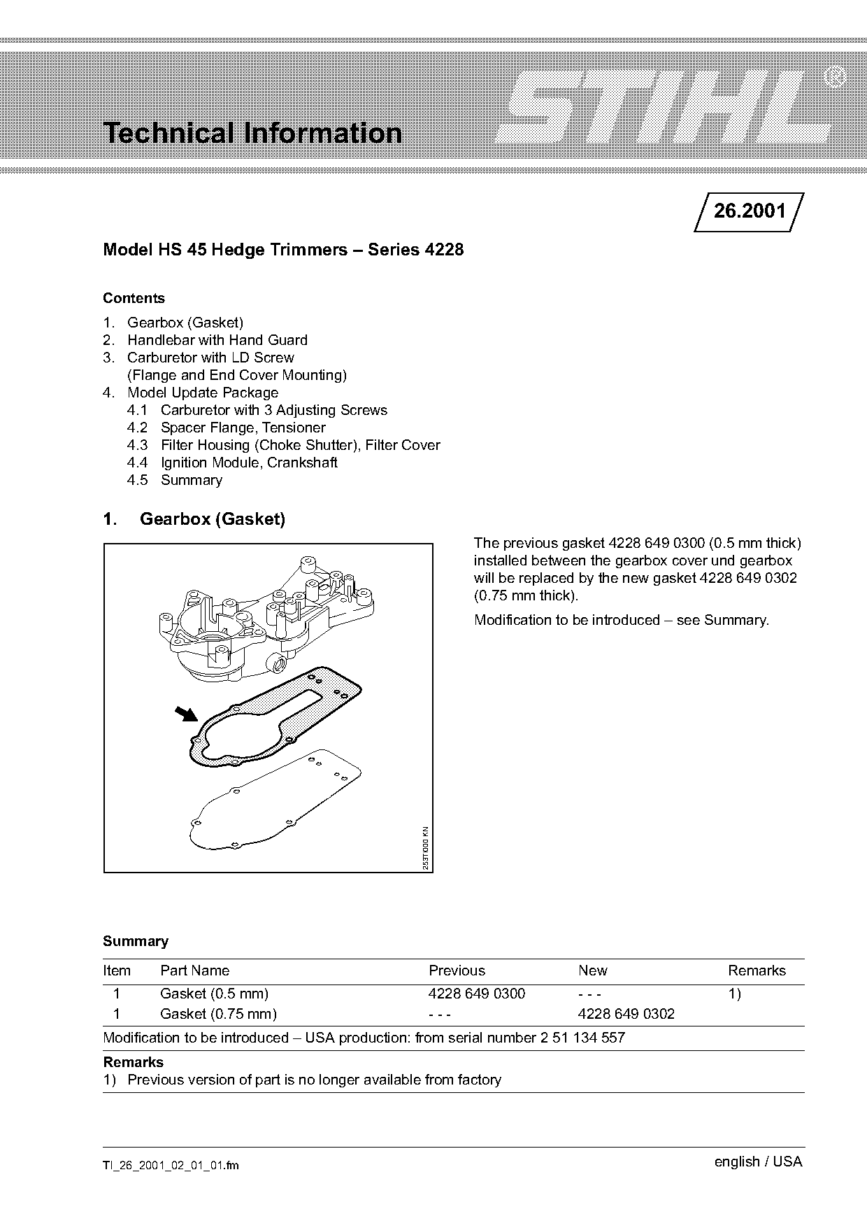
                                                                 The previous gasket 4228 649 0300 (0.5 mm thick)
                                                                 installed between the gearbox cover und gearbox
                                                                 will be replaced by the new gasket 4228 649 0302
                                                                 (0.75 mm thick).
                                                                 Modification to be introduced – see Summary.
                                                  253TI000 KN

Summary

Item     Part Name                                         Previous             New                   Remarks
 1       Gasket (0.5 mm)                                   4228 649 0300        ---                   1)
 1       Gasket (0.75 mm)                                  ---                  4228 649 0302
Modification to be introduced – USA production: from serial number 2 51 134 557
Remarks
1) Previous version of part is no longer available from factory

TI_26_2001_02_01_01.fm                                                                              english / USA
Page 2 of 7
Text of page 2 — search, copy, screen readers
Page 2                                                                                Technical Information 26.2001

2.       Handlebar with Hand Guard
The previous handlebar (front handle) with hand
guard 4228 791 0100 will be replaced by a fully
interchangeable version 4228 791 0101 in order to
further optimize component strength.

Summary

Item       Part Name                                       Previous              New                     Remarks
 1         Handlebar with hand guard                       4228 791 0100         4228 791 0101           1)

Remarks
1) Previous version of part is no longer available from factory

3.       Carburetor with LD Screw
         (Flange and End Cover Mounting)

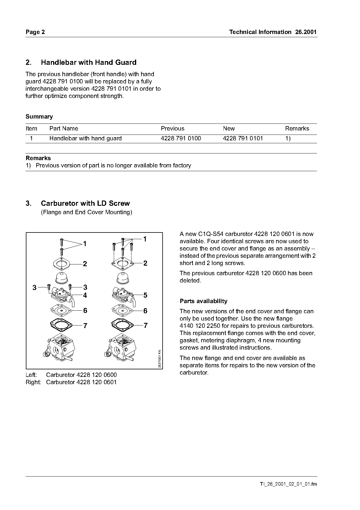
                                                                 A new C1Q-S54 carburetor 4228 120 0601 is now
                                            1                    available. Four identical screws are now used to
                       1
                                                                 secure the end cover and flange as an assembly –
                                                                 instead of the previous separate arrangement with 2
                       2                    2                    short and 2 long screws.
                                                                 The previous carburetor 4228 120 0600 has been
                                                                 deleted.
     3                 3
                       4                    5
                                                                 Parts availability
                       6                    6                    The new versions of the end cover and flange can
                                                                 only be used together. Use the new flange
                       7                    7                    4140 120 2250 for repairs to previous carburetors.
                                                                 This replacement flange comes with the end cover,
                                                                 gasket, metering diaphragm, 4 new mounting
                                                                 screws and illustrated instructions.
                                                  253TI001 KN

                                                                 The new flange and end cover are available as
                                                                 separate items for repairs to the new version of the
Left: Carburetor 4228 120 0600                                   carburetor.
Right: Carburetor 4228 120 0601

                                                                                                TI_26_2001_02_01_01.fm
Page 3 of 7
Text of page 3 — search, copy, screen readers
Technical Information 26.2001                                                                                 Page 3

Summary

Item     Part Name                                         Previous              New                     Remarks
         Carburetor C1Q-S49B;                              4228 120 0600         ---                     1)
         including items 1 to 4, 6, 7:
         Carburetor C1Q-S54;                               ---                   4228 120 0601
         including items 1, 2, 5 to 7:
 1       Screw                                             4226 122 7100         4226 122 7100           2)
 2       End cover                                         4226 121 0800         4140 121 0800           3)
 3       Screw (2x)                                        1128 122 7100         ---                     3)
 4       Flange                                            4226 120 2200         ---                     3)
 5       Flange                                            ---                   4140 120 2200
 6       Metering diaphragm                                4129 121 4700         4129 121 4700
 7       Gasket                                            1129 129 0900         4129 129 0902           3)
 8       Flange; including                                 ---                   4140 120 2250           4)
         items 1, 2, 5 to 7

Remarks
1) Previous version of part is no longer available from factory
2) Quantity changed from 2 to 4
3) Previous version of part remains available for other models
4) Replacement part for carburetor 4228 120 0600

4.     Model Update Package
Modifications will come on line in the near future to further optimize functionality. The parts and assemblies
affected (carburetor with 3 adjusting screws, spacer flange, tensioner, filter housing, filter cover, ignition
module, crankshaft) are described in chapters 4.1. to 4.5.

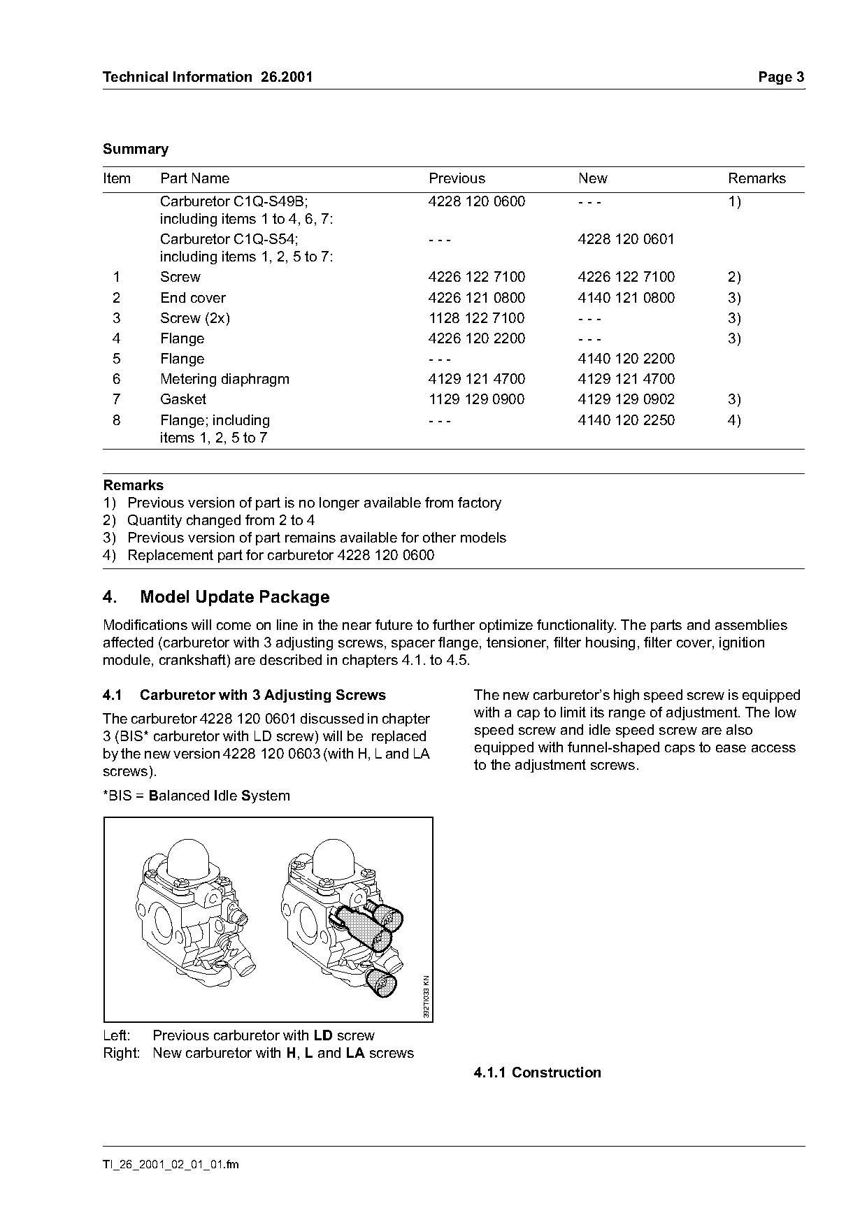
4.1    Carburetor with 3 Adjusting Screws                        The new carburetor’s high speed screw is equipped
The carburetor 4228 120 0601 discussed in chapter                with a cap to limit its range of adjustment. The low
3 (BIS* carburetor with LD screw) will be replaced               speed screw and idle speed screw are also
by the new version 4228 120 0603 (with H, L and LA               equipped with funnel-shaped caps to ease access
screws).                                                         to the adjustment screws.

*BIS = Balanced Idle System
                                                   392TI033 KN

Left: Previous carburetor with LD screw
Right: New carburetor with H, L and LA screws
                                                                 4.1.1 Construction

TI_26_2001_02_01_01.fm
Page 4 of 7
Text of page 4 — search, copy, screen readers
Page 4                                                                                 Technical Information 26.2001

                                                                   4.1.3 Repairs / servicing

     4                                       1
                                             2
                                                 3

                                                     392TI034 KN

                                                                                                                           392TI036 KN
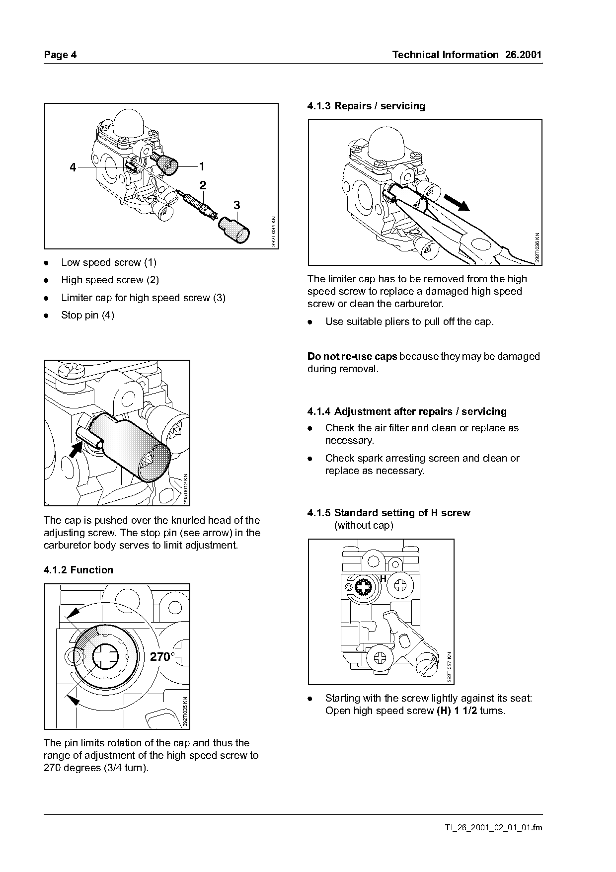
.   Low speed screw (1)
.   High speed screw (2)                                           The limiter cap has to be removed from the high
                                                                   speed screw to replace a damaged high speed
.   Limiter cap for high speed screw (3)
                                                                   screw or clean the carburetor.
.   Stop pin (4)
                                                                   .   Use suitable pliers to pull off the cap.

                                                                   Do not re-use caps because they may be damaged
                                                                   during removal.

                                                                   4.1.4 Adjustment after repairs / servicing
                                                                   .   Check the air filter and clean or replace as
                                                                       necessary.
                                                                   .   Check spark arresting screen and clean or
                                                                       replace as necessary.
                               295TI012 KN

                                                                   4.1.5 Standard setting of H screw
The cap is pushed over the knurled head of the
                                                                         (without cap)
adjusting screw. The stop pin (see arrow) in the
carburetor body serves to limit adjustment.

4.1.2 Function
                                                                                   H
                                                                                                   392TI037 KN

                       270°

                                                                   .   Starting with the screw lightly against its seat:
                              392TI035 KN

                                                                       Open high speed screw (H) 1 1/2 turns.

The pin limits rotation of the cap and thus the
range of adjustment of the high speed screw to
270 degrees (3/4 turn).

                                                                                                   TI_26_2001_02_01_01.fm
Page 5 of 7
Text of page 5 — search, copy, screen readers
Technical Information 26.2001                                                                        Page 5

4.1.6 Installing the cap                                4.1.9 Setting instructions for users
                                                        The user may adjust the carburetor’s high speed
                                                        screw within a range of 270 degrees.
                                                        This enables the user to make the mixture leaner if
                                                        necessary, e.g. for operation at high altitude.
                         H                              The procedure for setting the new carburetor is as
                                                        described in the owner’s manual (see chapter
                                                        "Adjusting the Carburetor").

                                                        4.2     Spacer Flange, Tensioner
                                392TI038 KN

                                                        The previous spacer flange 4140 121 1600 will be
                                                        replaced by the new version 4140 121 1605 when
                                                        the new carburetor is introduced (chapter 4.1). The
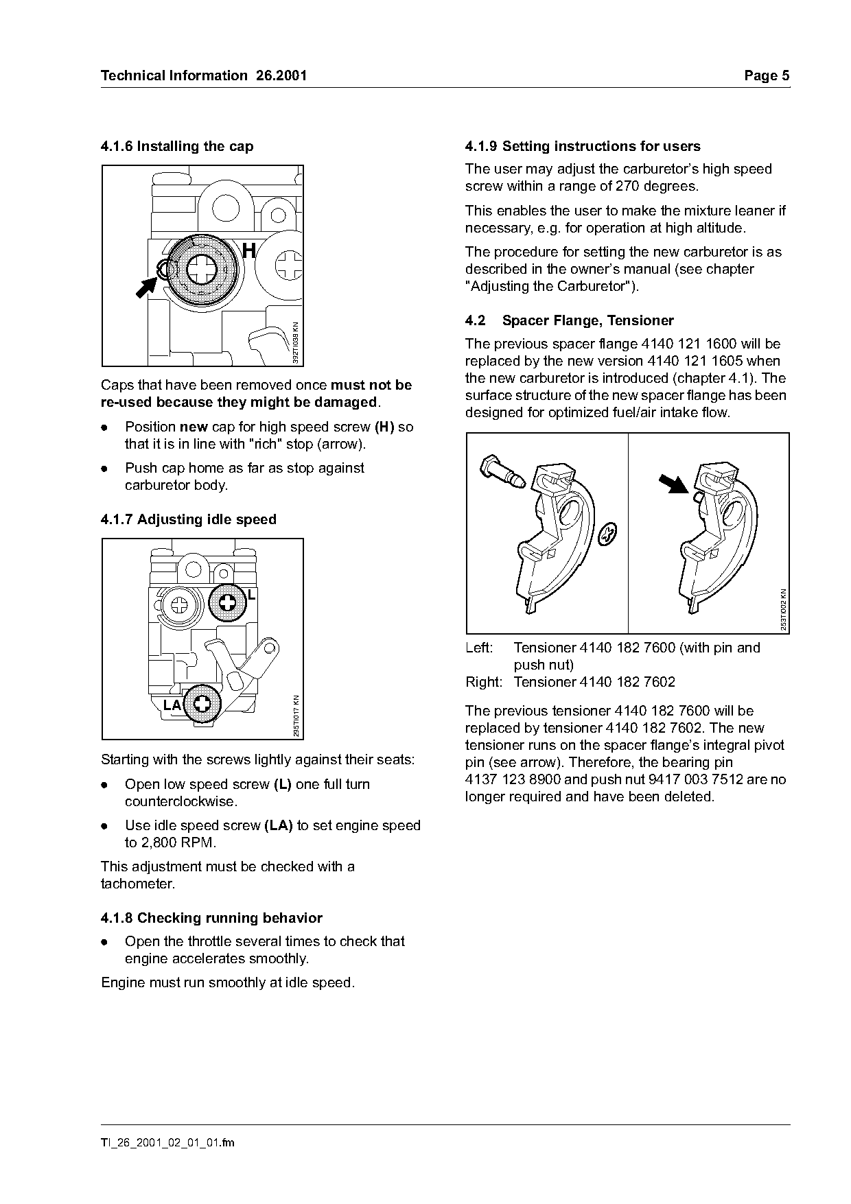
Caps that have been removed once must not be
                                                        surface structure of the new spacer flange has been
re-used because they might be damaged.
                                                        designed for optimized fuel/air intake flow.
.   Position new cap for high speed screw (H) so
    that it is in line with "rich" stop (arrow).
.   Push cap home as far as stop against
    carburetor body.

4.1.7 Adjusting idle speed

                                                                                                           253TI002 KN

                                                        Left:  Tensioner 4140 182 7600 (with pin and
                                                               push nut)
                                                        Right: Tensioner 4140 182 7602
                                 295TI017 KN

          LA                                            The previous tensioner 4140 182 7600 will be
                                                        replaced by tensioner 4140 182 7602. The new
                                                        tensioner runs on the spacer flange’s integral pivot
Starting with the screws lightly against their seats:   pin (see arrow). Therefore, the bearing pin
.   Open low speed screw (L) one full turn              4137 123 8900 and push nut 9417 003 7512 are no
    counterclockwise.                                   longer required and have been deleted.

.   Use idle speed screw (LA) to set engine speed
    to 2,800 RPM.
This adjustment must be checked with a
tachometer.

4.1.8 Checking running behavior
.   Open the throttle several times to check that
    engine accelerates smoothly.
Engine must run smoothly at idle speed.

TI_26_2001_02_01_01.fm
Page 6 of 7
Text of page 6 — search, copy, screen readers
Page 6                                                                                 Technical Information 26.2001

4.3   Filter Housing (Choke Shutter), Filter                       4.4   Ignition Module, Crankshaft
      Cover
Modified versions of the filter housing, choke shutter
and the filter cover will be installed at the same time
as the new carburetor described in chapter 4.1.

                                    H    L
                                   3/4   1

                                                                                                                        253TI004 KN
                 LD

                                                                   Position of slot for flywheel
                                                                   Left: Crankshaft 4228 030 0400
                                                     253TI003 KN

                                                                   Right: Crankshaft 4228 030 0402

                                                                   Ignition timing and cut-off speed range have been
                                                                   optimized. For this reason the previous ignition
                                                                   module 4140 400 1300 has been replaced by
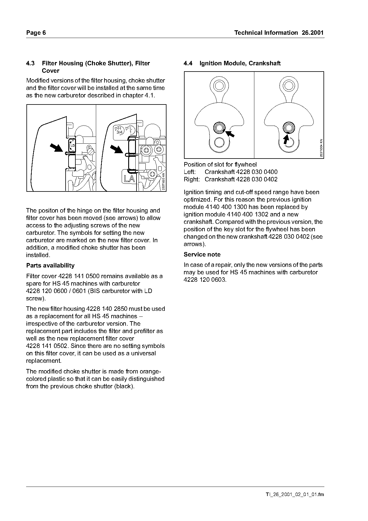
The positon of the hinge on the filter housing and
                                                                   ignition module 4140 400 1302 and a new
filter cover has been moved (see arrows) to allow
                                                                   crankshaft. Compared with the previous version, the
access to the adjusting screws of the new
                                                                   position of the key slot for the flywheel has been
carburetor. The symbols for setting the new
                                                                   changed on the new crankshaft 4228 030 0402 (see
carburetor are marked on the new filter cover. In
                                                                   arrows).
addition, a modified choke shutter has been
installed.                                                         Service note
Parts availability                                                 In case of a repair, only the new versions of the parts
                                                                   may be used for HS 45 machines with carburetor
Filter cover 4228 141 0500 remains available as a
                                                                   4228 120 0603.
spare for HS 45 machines with carburetor
4228 120 0600 / 0601 (BIS carburetor with LD
screw).
The new filter housing 4228 140 2850 must be used
as a replacement for all HS 45 machines –
irrespective of the carburetor version. The
replacement part includes the filter and prefilter as
well as the new replacement filter cover
4228 141 0502. Since there are no setting symbols
on this filter cover, it can be used as a universal
replacement.
The modified choke shutter is made from orange-
colored plastic so that it can be easily distinguished
from the previous choke shutter (black).

                                                                                                   TI_26_2001_02_01_01.fm
Page 7 of 7
Text of page 7 — search, copy, screen readers
Technical Information 26.2001                                                                         Page 7

4.5    Summary

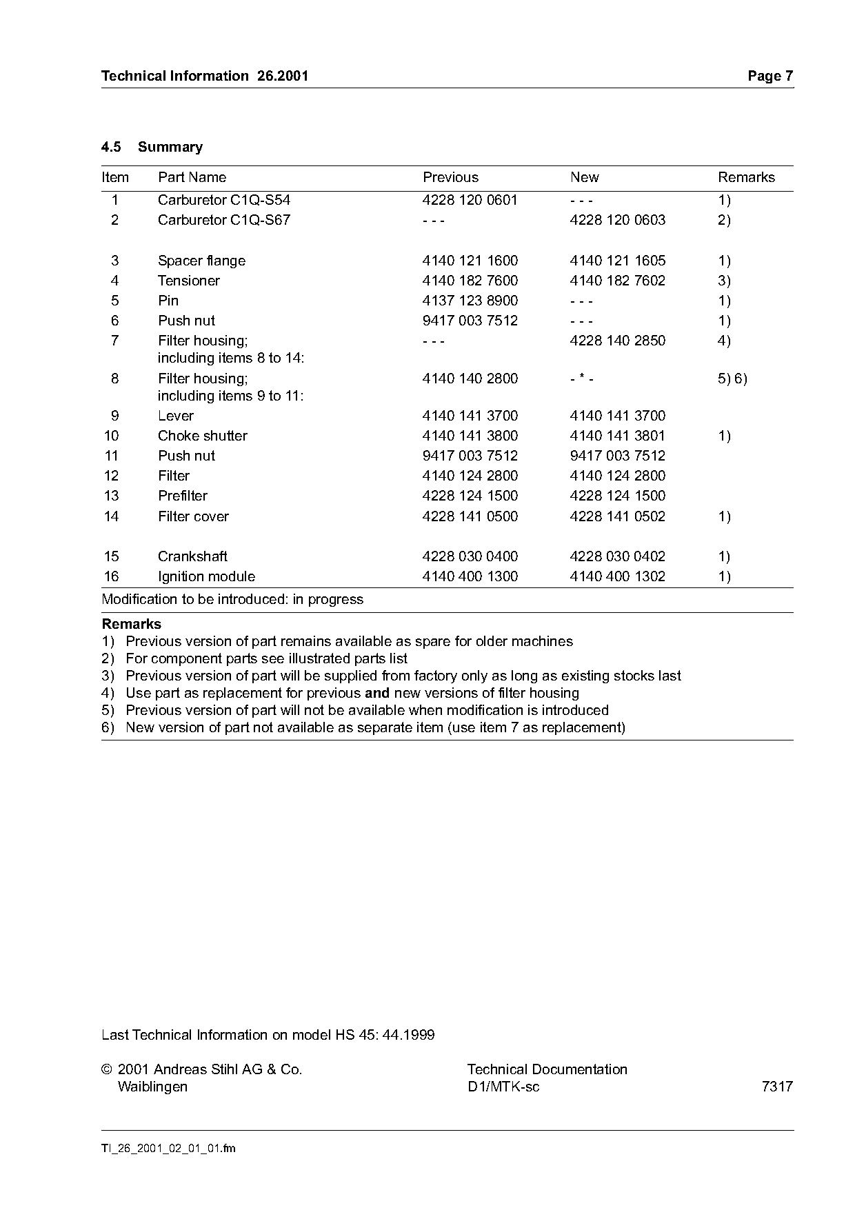
Item     Part Name                                  Previous                New                  Remarks
 1       Carburetor C1Q-S54                         4228 120 0601           ---                  1)
 2       Carburetor C1Q-S67                         ---                     4228 120 0603        2)

 3       Spacer flange                              4140 121 1600           4140 121 1605        1)
 4       Tensioner                                  4140 182 7600           4140 182 7602        3)
 5       Pin                                        4137 123 8900           ---                  1)
 6       Push nut                                   9417 003 7512           ---                  1)
 7       Filter housing;                            ---                     4228 140 2850        4)
         including items 8 to 14:
 8       Filter housing;                            4140 140 2800           -*-                  5) 6)
         including items 9 to 11:
 9       Lever                                      4140 141 3700           4140 141 3700
10       Choke shutter                              4140 141 3800           4140 141 3801        1)
11       Push nut                                   9417 003 7512           9417 003 7512
12       Filter                                     4140 124 2800           4140 124 2800
13       Prefilter                                  4228 124 1500           4228 124 1500
14       Filter cover                               4228 141 0500           4228 141 0502        1)

15       Crankshaft                                 4228 030 0400           4228 030 0402        1)
16       Ignition module                            4140 400 1300           4140 400 1302        1)
Modification to be introduced: in progress
Remarks
1) Previous version of part remains available as spare for older machines
2) For component parts see illustrated parts list
3) Previous version of part will be supplied from factory only as long as existing stocks last
4) Use part as replacement for previous and new versions of filter housing
5) Previous version of part will not be available when modification is introduced
6) New version of part not available as separate item (use item 7 as replacement)

Last Technical Information on model HS 45: 44.1999

© 2001 Andreas Stihl AG & Co.                              Technical Documentation
  Waiblingen                                               D1/MTK-sc                                     7317

TI_26_2001_02_01_01.fm
Most of these PDFs embed fonts with a shifted character map, so the text above was recovered rather than copied — read it as a faithful but imperfect transcription, and treat the page image above each block as the authority where the two disagree — the figures exist only there, because they are vector drawings that text extraction cannot keep.