Technical Information · issue 29 of 2001
Drive System
IssueTI 29/2001
Full text
Page 1 of 5
Text of page 1 — search, copy, screen readers
Technical Information

                                                                                              29.2001
SP 85, SP 85 K Special Harvesters – Series 4231

Contents
1. Drive System
   1.1 General Service Note

   1.2 Interchangeability and Features

   1.3 Clutch Drum / Drive Shaft
   1.4 Gearbox (ball bearings)
   1.5 Spring Damper

   1.6 Drive Tube Mounting on Gear Housing
   1.7 Summary

1.    Drive System
The drive system has been revised to further
                                                         The new assemblies or kits listed below should be
increase the durability and reliability of SP 85 and     installed when carrying out repairs to the drive
SP 85 K olive harvesters. This involved                  system of the machines described as new in
modifications and improvements in the area of the        TI 43.2000.
clutch and spring damper.

One of the modifications is not interchangeable, i.e.
cannot be combined with parts of earlier versions of     1.2   Interchangeability and Features
the machines.

                                                         1.2.1 Interchangeability
In order to ensure interchangeability in spare parts,

a kit will be supplied from the factory instead of the   The non-interchangeable modification in the area of
previous individual spare parts.                         the clutch and drive shaft (see 1.3) means that
                                                         earlier, previous and new versions of the powerhead
To guarantee the interchangeability of the
                                                         and attachment cannot always be combined with

powerhead and attachment: See chapter 1.2
                                                         each other.
“Interchangeability and Features”.

                                                         It was necessary to change the part numbers for
1.1   General Service Note                               powerheads and attachments because they may be
                                                         supplied separately to dealers and service, and the

Always observe the explanations and notes in
                                                         attachments have no serial numbers. Using the part
TI 43.2000 when carrying out repair work on earlier
                                                         numbers of the previous and new versions it is
versions of the machines. The notes in this technical

                                                         possible to correctly assign powerheads to the
information bulletin on interchangeability refer only
                                                         respective attachments.
to the new versions in TI 43.2000.

TI_29_2001_01_01_01.fm                                                                    englisch / english
Page 2 of 5
Text of page 2 — search, copy, screen readers
Page 2                                                                                       Technical Information 29.2001

 1.2.2 Features                                                          Attachment
 The new versions of the attachment and powerhead                        The new attachments can be identified with the aid
 can be identified with the help of the characteristic                   of the following features:
 features described below.
                                                                         .   Splined drive shaft which projects from the
 Powerhead                                                                   drive tube (see 1.3).


                                                                                                                            410TI009 KN
                                                                         .   The date of manufacture is shown as a
                                                                             two-letter code on the gear housing.
                                                                         Key to letter code:
                                                         410TI008 KN

                                                                         1st letter = year           2nd letter = month
                                              2                          A = 2000                    A = January
                                                                         B = 2001                    B = February
 Left: Previous powerhead

 Right: New powerhead                                                    C = 2002                    C = March
                                                                         D = etc.                    D = etc.

 The new powerhead can be easily identified by the

 following features, also described in TI 16.2001                        The date of manufacture of the new attachments

 (model update):                                                         began with BG (July 2001).
 .       The underside of the fan housing (arrow 1) is                   The date of manufacture of previous machines was
         reinforced.                                                     engraved on the gear housing as follows: 19/10/00

 .       The model nameplate (arrow 2) is now on the                     (19 October 2000, i.e. model year 2000).
         cover of the rewind starter.

 1.2.3 Summary

 Item         Part Name                                           Previous               New                      Remarks
     1        Powerhead SP 85 / SP 85 K                            4231 011 1800         4231 011 1804            1)

     2        Attachment SP 85 (2 m)                               4231 740 4100         4231 740 4104            2)
     3        Attachment SP 85 K (1m)                              4231 740 4103         4231 740 4105            2)
 Modification to be introduced: in progress
 Remarks
 1) Only the previous version is available from the factory
 2) Only the new version is available from the factory

                                                                                                       TI_29_2001_01_01_01.fm
Page 3 of 5
Text of page 3 — search, copy, screen readers
Technical Information 29.2001                                                                                       Page 3

1.3   Clutch Drum / Drive Shaft
                                                                  It is also advisable to install the drive shaft kit on new
                                                                  machine versions because the contact areas of the
                                                                  clutch drum and drive shaft wear at the same rate.

                                                                  1.3.2 Note on Spare Parts (drive shaft)
                                                                  For production reasons drive shaft 4231 710 3201
                                                                  was supplied as a replacement part for an interim
                                                                  period in place of drive shaft 4231 711 3201. Both
                                                                  these shafts are fully interchangeable (square

                                                                  section). All references to drive shaft 4231 711 3201

                                                                  in this publication also apply to 4231 710 3201.

                                                    409TI011 KN
                                                                  1.4   Gearbox (ball bearings)

Clutch drum and drive shaft
Left: Previous version
Right: New version
                                                                                                               1
The connection between the clutch drum and drive
shaft has been changed from a square section to a

splined section in order to improve fatigue strength.
New versions of the clutch drum and drive shaft may
only be used in previous machine versions as

matching pairs.                                                                                                1
A drive shaft kit 4231 710 3250 is available from the

factory to ensure troublefree installation in previous
machine versions. This kit contains the new

                                                                                                                          410TI010 KN
versions of the clutch drum and drive shaft.

1.3.1 Service Note                                                The ball bearing 9503 003 9543 (1), which was not
When performing repairs on previous and new                       previously available as a separate item, is now
machine versions, check the wear in the hub of the                supplied as a spare part from the factory.

clutch drum and on the end of the drive shaft and                 This ball bearing can be used for all versions of the
replace if necessary. On previous machine versions,               gear housing and cover.
use the drive shaft kit 4231 710 3250 for this

purpose.

TI_29_2001_01_01_01.fm
Page 4 of 5
Text of page 4 — search, copy, screen readers
Page 4                                                                                 Technical Information 29.2001

1.5   Spring Damper
                                                                    Service Note
                                                                    When carrying out general servicing work in the
                                                                    area of the drive tube and spring damper, install new
                         1                                          blue dampers in place of all four black dampers (3).

                                                                    1.6   Drive Tube Mounting on Gear Housing


          3                                                                                        2    1

                                                  409TI015 KN

                               3
                                                                                3

                                                                                                                       409TI016 KN
Spring damper (1) with a detailed view of left-hand
half. There are also two dampers (3) in the right-
hand half.
                                                                    The previous screws (1) used to secure the drive
The rating of the spring damper (1) has been                        tube (2) to the gear housing (3) have been replaced
changed by modifying the material properties of the                 by screws with different strength properties.

springs (2) and the four dampers (3; sleeve).
                                                                    Previous and new versions of the screws are fully
The part numbers of the modified the springs and                    interchangeable in both previous and new machine
dampers remain unchanged.                                           versions.

The previous and new versions of the damper (3)                     Note:

can be identified by their different colors:                        This change was described in TI 43.2000,
Version          Color             Material                         1.4 Summary, items 32 and 33t, but was only
                                                                    implemented with the introduction of the new
Previous         black             NBR
                                                                    attachments. the wrong screw type was listed in the

New version      blue              polyurethane                     Summary of TI 43.2000 (item 33).

                                                                                                   TI_29_2001_01_01_01.fm
Page 5 of 5
Text of page 5 — search, copy, screen readers
Technical Information 29.2001                                                                             Page 5

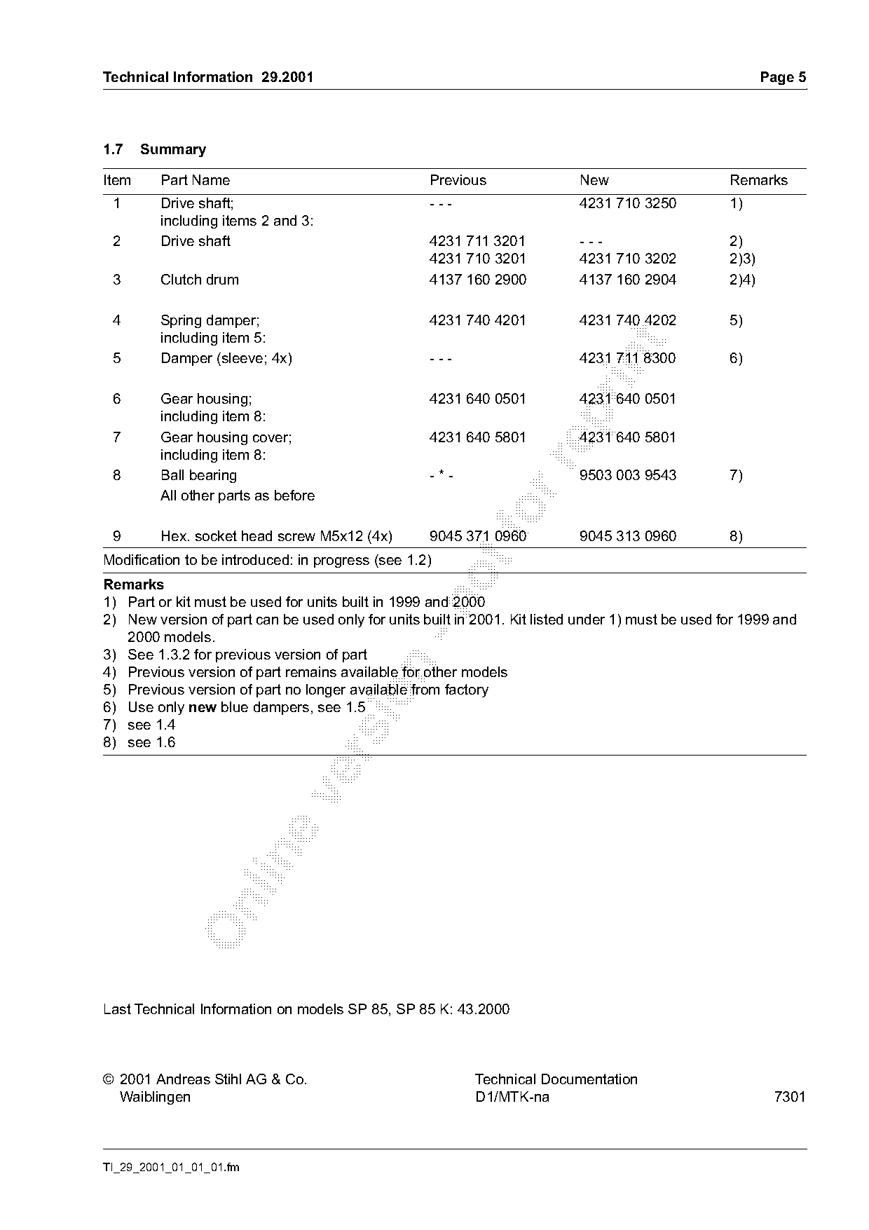
1.7    Summary

Item     Part Name                                 Previous                New                     Remarks
 1       Drive shaft;                              ---                     4231 710 3250           1)
         including items 2 and 3:
 2       Drive shaft                               4231 711 3201           ---                     2)
                                                   4231 710 3201           4231 710 3202           2)3)
 3       Clutch drum                               4137 160 2900           4137 160 2904           2)4)

 4       Spring damper;                            4231 740 4201           4231 740 4202           5)
         including item 5:

 5       Damper (sleeve; 4x)                       ---                     4231 711 8300           6)

 6       Gear housing;                             4231 640 0501           4231 640 0501

         including item 8:
 7       Gear housing cover;                       4231 640 5801           4231 640 5801
         including item 8:

 8       Ball bearing                              -*-                     9503 003 9543           7)
         All other parts as before

 9       Hex. socket head screw M5x12 (4x)
                                                   9045 371 0960           9045 313 0960           8)
Modification to be introduced: in progress (see 1.2)
Remarks
1) Part or kit must be used for units built in 1999 and 2000

2) New version of part can be used only for units built in 2001. Kit listed under 1) must be used for 1999 and
   2000 models.
3) See 1.3.2 for previous version of part

4) Previous version of part remains available for other models
5) Previous version of part no longer available from factory

6) Use only new blue dampers, see 1.5
7) see 1.4
8) see 1.6

Last Technical Information on models SP 85, SP 85 K: 43.2000

© 2001 Andreas Stihl AG & Co.                              Technical Documentation
  Waiblingen                                               D1/MTK-na                                       7301

TI_29_2001_01_01_01.fm
Most of these PDFs embed fonts with a shifted character map, so the text above was recovered rather than copied — read it as a faithful but imperfect transcription, and treat the page image above each block as the authority where the two disagree — the figures exist only there, because they are vector drawings that text extraction cannot keep.