Technical Information · issue 41 of 2001
Great Britain and New Zealand only - Technical Des
Model FS 55 RT is included in the illustrated parts Arbor Bearings
IssueTI 41/2001
Full text
Page 1 of 12
Text of page 1 — search, copy, screen readers
Technical Information

                                                                                           41.2001
New Model FS 55 RT Brushcutter – Series 4140

Contents
1.   Technical Description
2.   Specifications

3.   Tools

4.   User Accessories
5.   Service Accessories
6.   Repairs

7.   Spare Parts

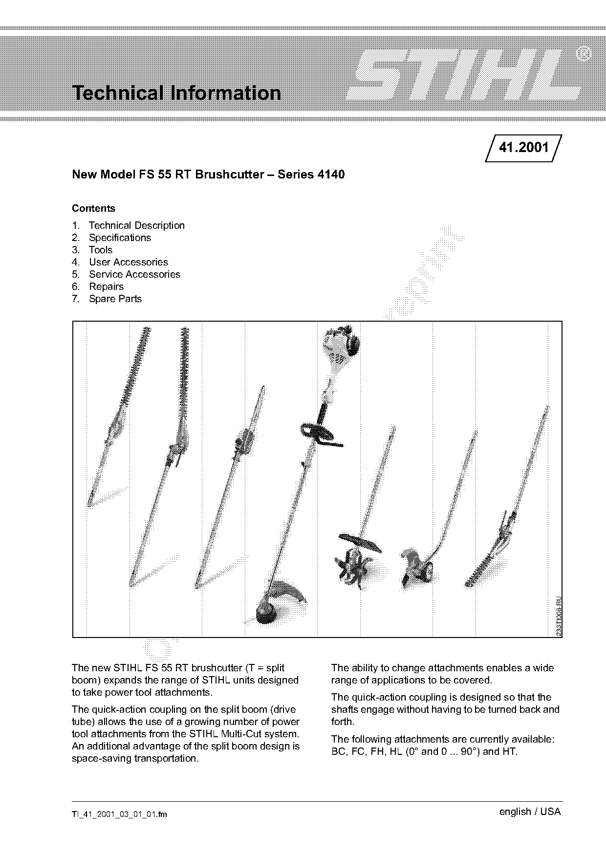
The new STIHL FS 55 RT brushcutter (T = split         The ability to change attachments enables a wide
boom) expands the range of STIHL units designed       range of applications to be covered.
to take power tool attachments.
                                                      The quick-action coupling is designed so that the
The quick-action coupling on the split boom (drive    shafts engage without having to be turned back and
tube) allows the use of a growing number of power     forth.
tool attachments from the STIHL Multi-Cut system.
                                                      The following attachments are currently available:
An additional advantage of the split boom design is
                                                      BC, FC, FH, HL (0° and 0 ... 90°) and HT.
space-saving transportation.

TI_41_2001_03_01_01.fm                                                                     english / USA
Page 2 of 12
Text of page 2 — search, copy, screen readers
Page 2                                                               Technical Information 41.2001

The engine (series 4140 powerhead) and
ergonomically designed controls are exactly the
same as those of the loop-handle FS 55.
This means that the brushcutter is the basic power
unit for numerous attachments with a broad range of
applications.

1.     Technical Description

Engine, controls and handle system same as
loop-handle FS 55

Split Boom / Drive Shafts
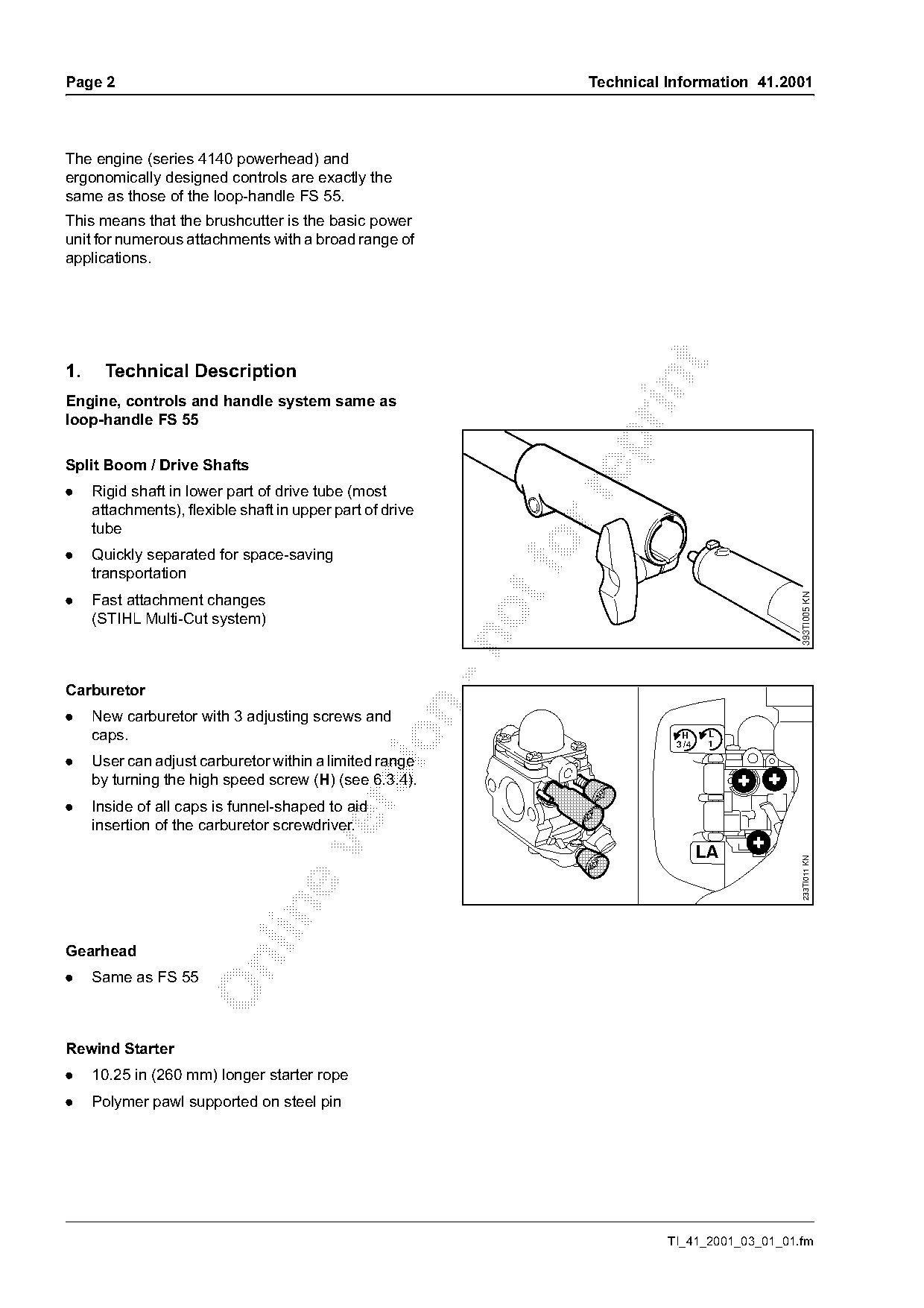
.    Rigid shaft in lower part of drive tube (most

     attachments), flexible shaft in upper part of drive
     tube
.    Quickly separated for space-saving
     transportation
.    Fast attachment changes

                                                                                                   393TI005 KN
     (STIHL Multi-Cut system)

Carburetor

.    New carburetor with 3 adjusting screws and
     caps.

                                                                                 H      L
                                                                                3 /4    1

.    User can adjust carburetor within a limited range
     by turning the high speed screw (H) (see 6.3.4).

.    Inside of all caps is funnel-shaped to aid
     insertion of the carburetor screwdriver.

                                                                                       LA
                                                                                                   233TI011 KN

Gearhead

.    Same as FS 55

Rewind Starter
.    10.25 in (260 mm) longer starter rope
.    Polymer pawl supported on steel pin

                                                                               TI_41_2001_03_01_01.fm
Page 3 of 12
Text of page 3 — search, copy, screen readers
Technical Information 41.2001                                                                 Page 3

2.    Specifications

2.1   Powerhead

2.1.1 Engine

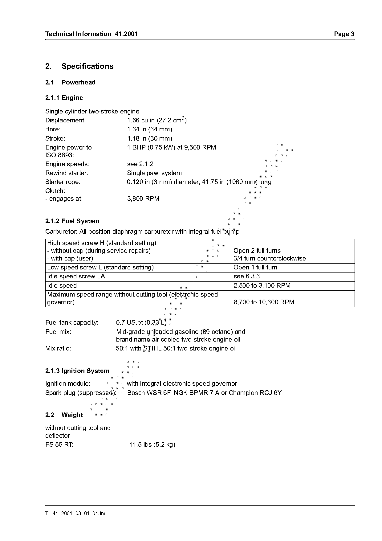
Single cylinder two-stroke engine
Displacement:                1.66 cu.in (27.2 cm3)
Bore:                        1.34 in (34 mm)
Stroke:                      1.18 in (30 mm)
Engine power to              1 BHP (0.75 kW) at 9,500 RPM

ISO 8893:

Engine speeds:               see 2.1.2
Rewind starter:              Single pawl system
Starter rope:                0.120 in (3 mm) diameter, 41.75 in (1060 mm) long

Clutch:
- engages at:                3,800 RPM

2.1.2 Fuel System
Carburetor: All position diaphragm carburetor with integral fuel pump
High speed screw H (standard setting)
- without cap (during service repairs)                            Open 2 full turns
- with cap (user)                                                 3/4 turn counterclockwise

Low speed screw L (standard setting)                              Open 1 full turn
Idle speed screw LA                                               see 6.3.3
Idle speed                                                        2,500 to 3,100 RPM

Maximum speed range without cutting tool (electronic speed
governor)                                                         8,700 to 10,300 RPM

Fuel tank capacity:        0.7 US.pt (0.33 L)
Fuel mix:                  Mid-grade unleaded gasoline (89 octane) and

                           brand.name air cooled two-stroke engine oil
Mix ratio:                 50:1 with STIHL 50:1 two-stroke engine oi

2.1.3 Ignition System

Ignition module:              with integral electronic speed governor
Spark plug (suppressed):      Bosch WSR 6F, NGK BPMR 7 A or Champion RCJ 6Y

2.2   Weight

without cutting tool and
deflector
FS 55 RT:                      11.5 lbs (5.2 kg)

TI_41_2001_03_01_01.fm
Page 4 of 12
Text of page 4 — search, copy, screen readers
Page 4                                                       Technical Information 41.2001

3.      Tools

3.1     FS Cutting Tools
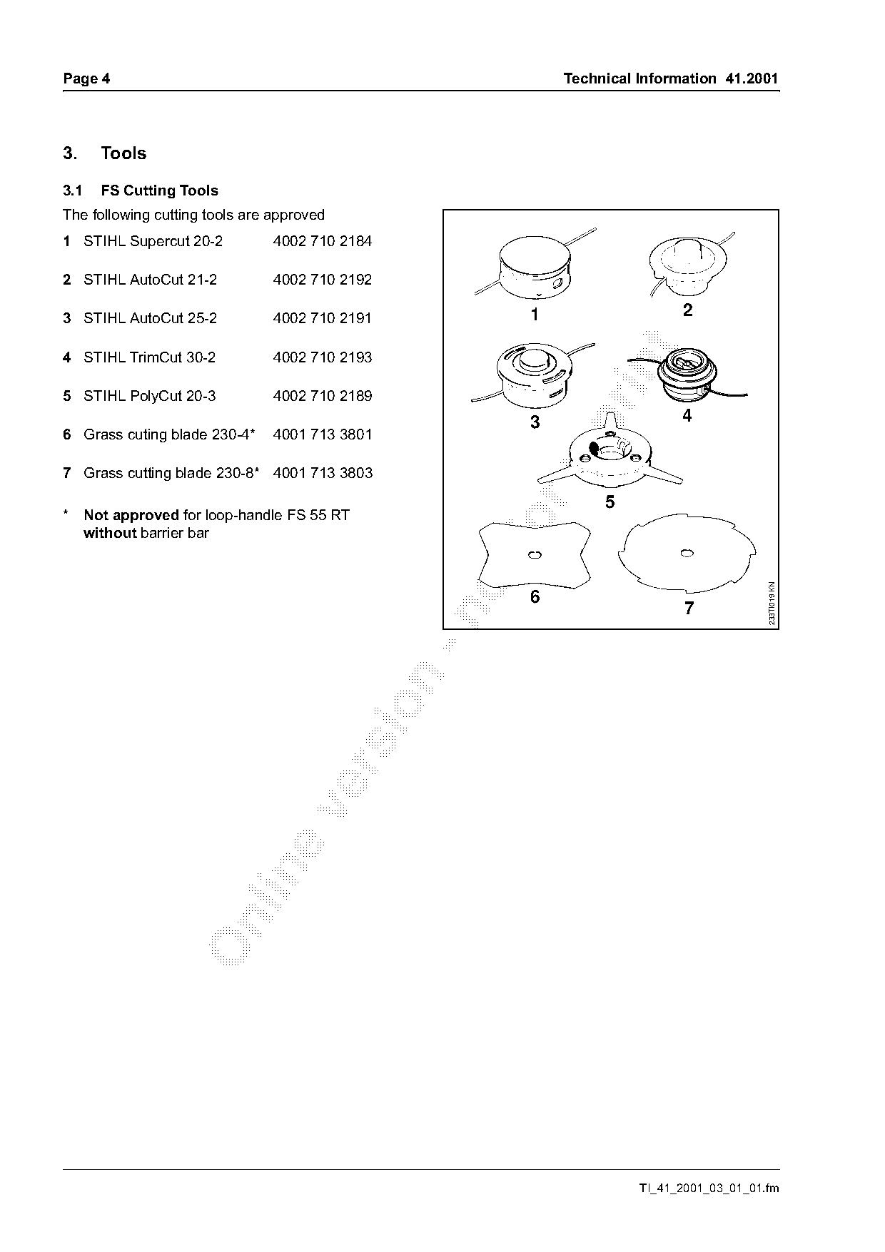
The following cutting tools are approved
1 STIHL Supercut 20-2           4002 710 2184

2 STIHL AutoCut 21-2            4002 710 2192

3 STIHL AutoCut 25-2            4002 710 2191            1                   2

4 STIHL TrimCut 30-2            4002 710 2193

5 STIHL PolyCut 20-3            4002 710 2189
                                                                             4

                                                         3
6 Grass cuting blade 230-4*     4001 713 3801

7 Grass cutting blade 230-8* 4001 713 3803

                                                                  5
*     Not approved for loop-handle FS 55 RT
      without barrier bar                            fo

                                                                                           233TI019 KN
                                                         6
                                                                              7

                                                                       TI_41_2001_03_01_01.fm
Page 5 of 12
Text of page 5 — search, copy, screen readers
Technical Information 41.2001                                               Page 5

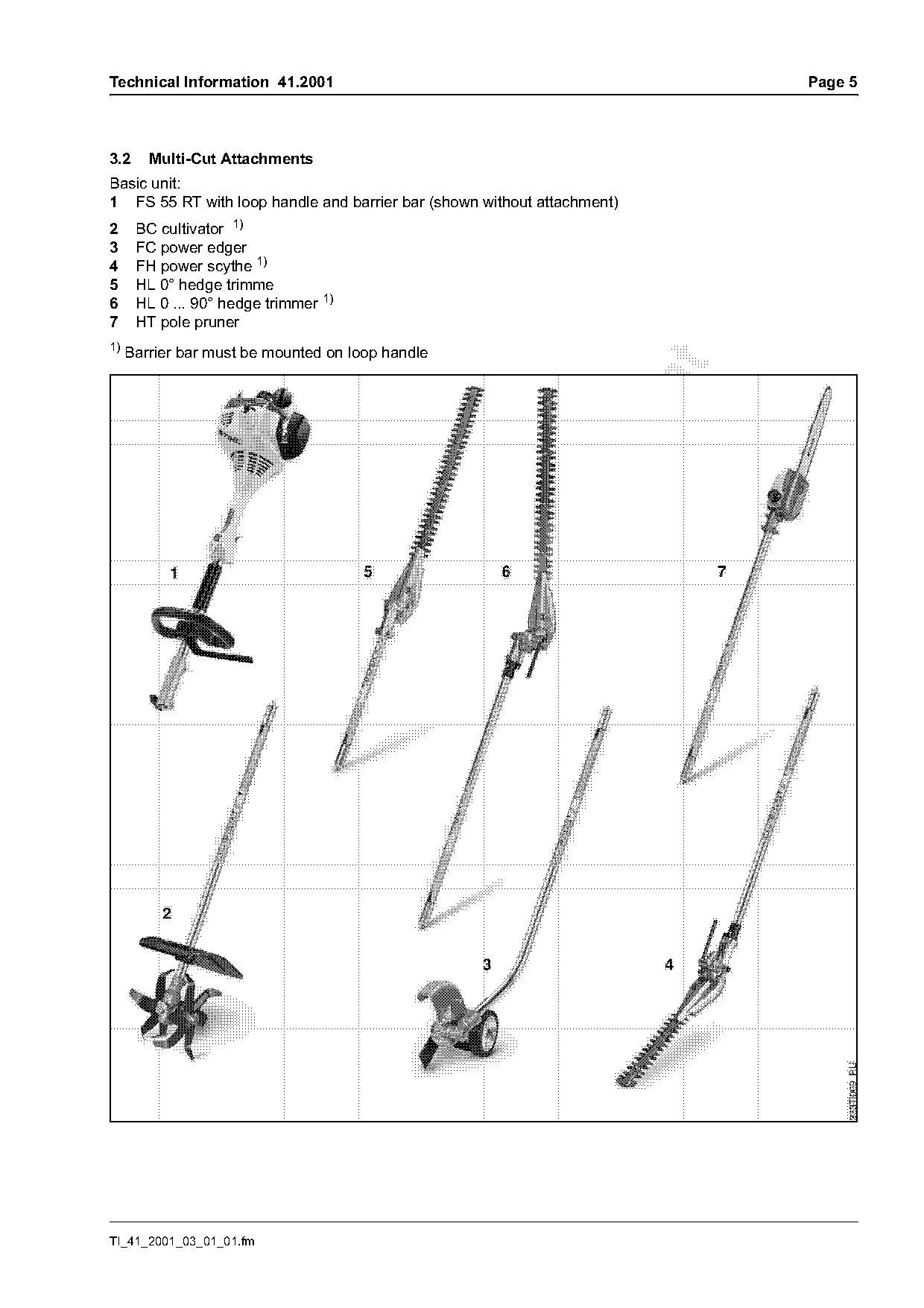
3.2     Multi-Cut Attachments
Basic unit:
1 FS 55 RT with loop handle and barrier bar (shown without attachment)
2     BC cultivator 1)
3     FC power edger
4     FH power scythe 1)
5     HL 0° hedge trimme
6     HL 0 ... 90° hedge trimmer 1)
7     HT pole pruner
1)
     Barrier bar must be mounted on loop handle

TI_41_2001_03_01_01.fm
Page 6 of 12
Text of page 6 — search, copy, screen readers
Page 6                                                                      Technical Information 41.2001

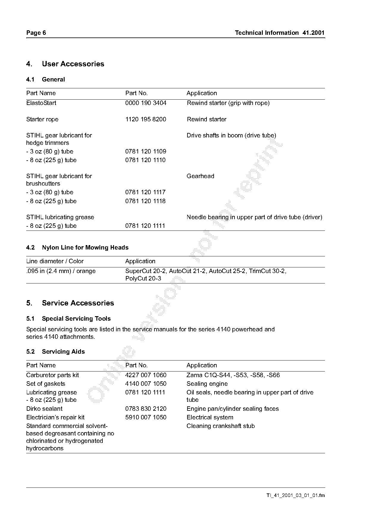
4.    User Accessories

4.1   General

Part Name                           Part No.              Application
ElastoStart                         0000 190 3404         Rewind starter (grip with rope)

Starter rope                        1120 195 8200         Rewind starter

STIHL gear lubricant for                                  Drive shafts in boom (drive tube)
hedge trimmers

- 3 oz (80 g) tube                  0781 120 1109

- 8 oz (225 g) tube                 0781 120 1110

STIHL gear lubricant for                                  Gearhead

brushcutters
- 3 oz (80 g) tube                  0781 120 1117

- 8 oz (225 g) tube                 0781 120 1118

STIHL lubricating grease
- 8 oz (225 g) tube                 0781 120 1111
                                                          Needle bearing in upper part of drive tube (driver)
4.2   Nylon Line for Mowing Heads

Line diameter / Color               Application
.095 in (2.4 mm) / orange           SuperCut 20-2, AutoCut 21-2, AutoCut 25-2, TrimCut 30-2,
                                    PolyCut 20-3

5.    Service Accessories

5.1   Special Servicing Tools

Special servicing tools are listed in the service manuals for the series 4140 powerhead and
series 4140 attachments.

5.2   Servicing Aids

Part Name                           Part No.              Application
Carburetor parts kit                4227 007 1060         Zama C1Q-S44, -S53, -S58, -S66
Set of gaskets                      4140 007 1050         Sealing engine

Lubricating grease                  0781 120 1111         Oil seals, needle bearing in upper part of drive
- 8 oz (225 g) tube                                       tube
Dirko sealant                       0783 830 2120         Engine pan/cylinder sealing faces
Electrician’s repair kit            5910 007 1050         Electrical system
Standard commercial solvent-                              Cleaning crankshaft stub
based degreasant containing no
chlorinated or hydrogenated
hydrocarbons

                                                                                        TI_41_2001_03_01_01.fm
Page 7 of 12
Text of page 7 — search, copy, screen readers
Technical Information 41.2001                                                                          Page 7

6.      Repairs
If the unit is started up in the course of repairs, it is essential to strictly observe all country-specific
safety regulations and the safety precautions outlined in the owner’s manual.

6.1     Replacing and Lubricating the Shafts

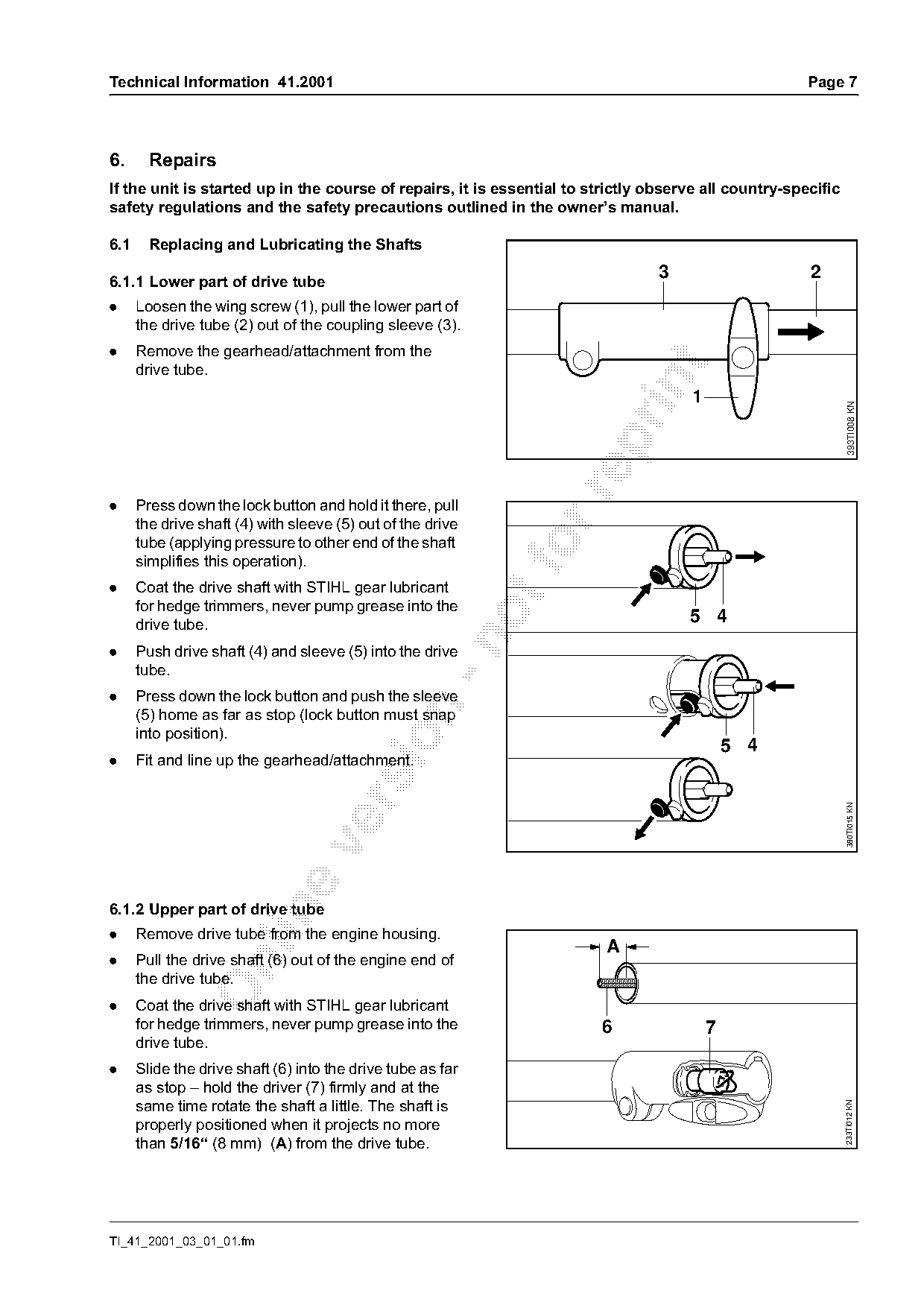
6.1.1 Lower part of drive tube
                                                                                 3                     2
.     Loosen the wing screw (1), pull the lower part of
      the drive tube (2) out of the coupling sleeve (3).
.     Remove the gearhead/attachment from the

      drive tube.


                                                                                                                393TI008 KN
.     Press down the lock button and hold it there, pull
      the drive shaft (4) with sleeve (5) out of the drive
      tube (applying pressure to other end of the shaft       fo
      simplifies this operation).
.     Coat the drive shaft with STIHL gear lubricant
      for hedge trimmers, never pump grease into the
      drive tube.                                                                    5 4

.     Push drive shaft (4) and sleeve (5) into the drive
      tube.
.     Press down the lock button and push the sleeve

      (5) home as far as stop (lock button must snap
      into position).

                                                                                              5 4
.     Fit and line up the gearhead/attachment.

                                                                                                                380TI015 KN

6.1.2 Upper part of drive tube

.     Remove drive tube from the engine housing.
                                                                         A
.     Pull the drive shaft (6) out of the engine end of

      the drive tube.
.     Coat the drive shaft with STIHL gear lubricant
      for hedge trimmers, never pump grease into the                    6                 7
      drive tube.
.     Slide the drive shaft (6) into the drive tube as far
      as stop – hold the driver (7) firmly and at the
      same time rotate the shaft a little. The shaft is
                                                                                                               233TI012 KN

      properly positioned when it projects no more
      than 5/16“ (8 mm) (A) from the drive tube.

TI_41_2001_03_01_01.fm
Page 8 of 12
Text of page 8 — search, copy, screen readers
Page 8                                                                 Technical Information 41.2001

.     Install drive tube in engine housing.
.     Finally, refit lower part of drive tube with
      gearhead/attachment.

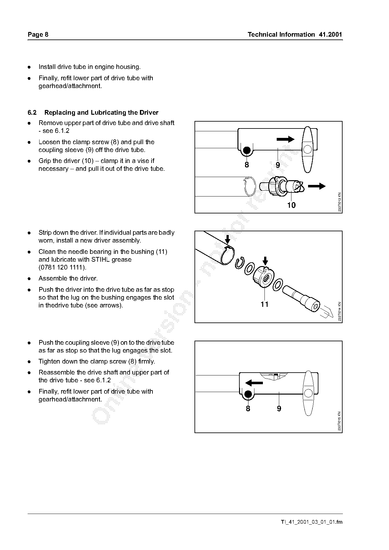
6.2     Replacing and Lubricating the Driver
.     Remove upper part of drive tube and drive shaft
      - see 6.1.2
.     Loosen the clamp screw (8) and pull the
      coupling sleeve (9) off the drive tube.

.     Grip the driver (10) – clamp it in a vise if

      necessary – and pull it out of the drive tube.
                                                                       8        9

                                                                                                         233TI013 KN
                                                                                      10

.     Strip down the driver. If individual parts are badly
      worn, install a new driver assembly.
.     Clean the needle bearing in the bushing (11)
      and lubricate with STIHL grease
      (0781 120 1111).

.     Assemble the driver.
.     Push the driver into the drive tube as far as stop
      so that the lug on the bushing engages the slot

      in thedrive tube (see arrows).                                       11

                                                                                                         233TI014 KN

.     Push the coupling sleeve (9) on to the drive tube
      as far as stop so that the lug engages the slot.

.     Tighten down the clamp screw (8) firmly.
.     Reassemble the drive shaft and upper part of
      the drive tube - see 6.1.2

.     Finally, refit lower part of drive tube with
      gearhead/attachment.

                                                                       8        9
                                                                                                        233TI015 KN

                                                                                    TI_41_2001_03_01_01.fm
Page 9 of 12
Text of page 9 — search, copy, screen readers
Technical Information 41.2001                                                                                          Page 9

6.3    Carburetor

6.3.1 Construction                                                      6.3.3 Repairs / Servicing

       4                                        1
                                                2


                                                          233TI016 KN

                                                                                                                                392TI036 KN
                             5

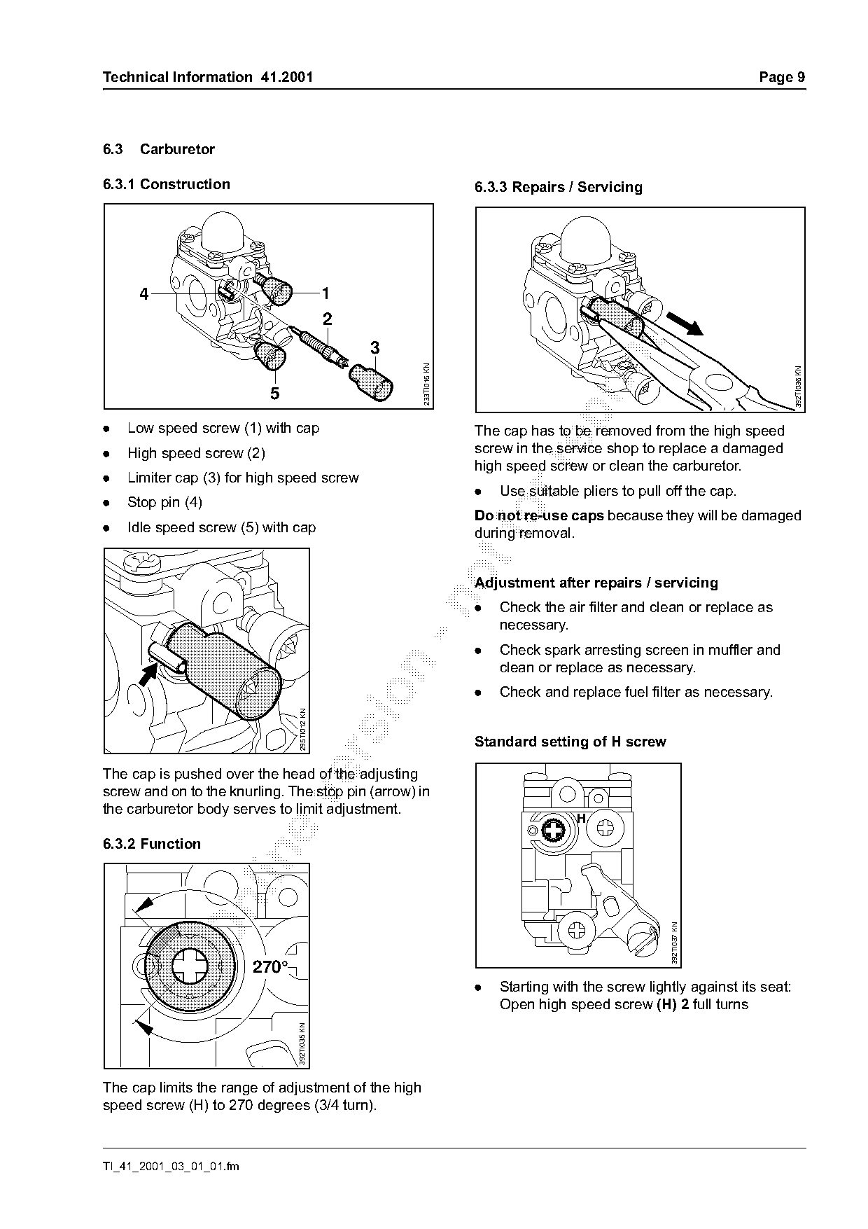
.     Low speed screw (1) with cap                                      The cap has to be removed from the high speed
.     High speed screw (2)                                              screw in the service shop to replace a damaged

                                                                        high speed screw or clean the carburetor.
.     Limiter cap (3) for high speed screw
                                                                        .   Use suitable pliers to pull off the cap.
.     Stop pin (4)
.     Idle speed screw (5) with cap
                                                                        Do not re-use caps because they will be damaged
                                                                        during removal.
                                                                        Adjustment after repairs / servicing

                                                                        .   Check the air filter and clean or replace as
                                                                            necessary.
                                                                        .   Check spark arresting screen in muffler and
                                                                            clean or replace as necessary.

                                                                        .   Check and replace fuel filter as necessary.
                                  295TI012 KN

                                                                        Standard setting of H screw

The cap is pushed over the head of the adjusting
screw and on to the knurling. The stop pin (arrow) in

the carburetor body serves to limit adjustment.
                                                                                        H

6.3.2 Function

                                                                                                        392TI037 KN

                         270°
                                                                        .   Starting with the screw lightly against its seat:
                                                                            Open high speed screw (H) 2 full turns
                                 392TI035 KN

The cap limits the range of adjustment of the high
speed screw (H) to 270 degrees (3/4 turn).

TI_41_2001_03_01_01.fm
Page 10 of 12
Text of page 10 — search, copy, screen readers
Page 10                                                                          Technical Information 41.2001

Installing the cap                                          Checking running behavior
                                                            .     Open the throttle several times to check that
                                                                  engine accelerates smoothly.
                                                            .     Engine must run smoothly at idle speed.

                       H
                                                            6.3.4 Setting instructions for users
                                392TI038 KN

Caps that have been removed once must not be                                          270°
re-used because they will be damaged.

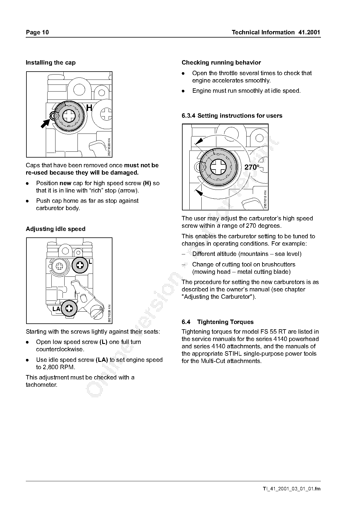
.   Position new cap for high speed screw (H) so
    that it is in line with “rich” stop (arrow).

                                                                                             295TI013 KN
.   Push cap home as far as stop against
    carburetor body.
                                                            The user may adjust the carburetor’s high speed
                                                            screw within a range of 270 degrees.
Adjusting idle speed
                                                            This enables the carburetor setting to be tuned to
                                                            changes in operating conditions. For example:

                                                            –     Different altitude (mountains – sea level)
                        L                                   –     Change of cutting tool on brushcutters
                                                                  (mowing head – metal cutting blade)

                                                            The procedure for setting the new carburetors is as
                                                            described in the owner’s manual (see chapter

                                                            "Adjusting the Carburetor").
                                 392TI039 KN


                                                            6.4     Tightening Torques
Starting with the screws lightly against their seats:       Tightening torques for model FS 55 RT are listed in

                                                            the service manuals for the series 4140 powerhead
.   Open low speed screw (L) one full turn
                                                            and series 4140 attachments, and the manuals of
    counterclockwise.
                                                            the appropriate STIHL single-purpose power tools

.   Use idle speed screw (LA) to set engine speed           for the Multi-Cut attachments.
    to 2,800 RPM.
This adjustment must be checked with a

tachometer.

                                                                                             TI_41_2001_03_01_01.fm
Page 11 of 12
Text of page 11 — search, copy, screen readers
Technical Information 41.2001                                                                    Page 11

6.5   Service Note
For servicing and repairs procedures on the             Code Type of Repair                      FS 55 RT
FS 55 RT refer to the service manuals for the series    1    Crankcase, Crankshaft,               2.0
4140 powerhead and series 4140 attachments.                  Crankshaft Bearings
These service manuals do not include the chapters       2
"Servicing the Carburetor", "Troubleshooting" or any    3    Crankcase Gasket/Sealing             2.0
repairs involving standard procedures. Such
                                                        4    Crankshaft Seals (includes           1.0
procedures are described in separate handbooks,
                                                             pressure & vacuum testing)
i.e. “Carburetors” and "Standard Repairs,
                                                        5    Cylinder and/or Piston               1.0
Troubleshooting".
                                                        6    Ignition Module                      0.5
The manuals of the appropriate STIHL single-

                                                        7    Fuel Hose                            0.5

purpose power tools can be used for servicing and
repair procedures on the Multi-Cut attachments.         8    Replace Gear Box/Arbor Assy.         0.5
                                                        9    Repair/Rebuild Carburetor            0.8
                                                        10   Replace Carburetor, Carburetor       0.4

6.6   Repair Times                                           Jet (if tried to repair use code 9)
                                                        11   Front Handle, Throttle Control,      0.6
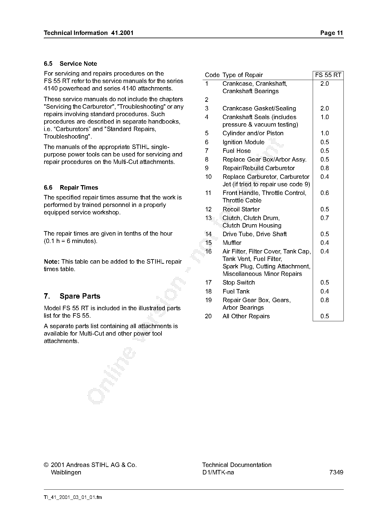
The specified repair times assume that the work is

                                                             Throttle Cable
performed by trained personnel in a properly
                                                        12   Recoil Starter                       0.5
equipped service workshop.
                                                        13   Clutch, Clutch Drum,
                                                             Clutch Drum Housing
                                                                                                  0.7

The repair times are given in tenths of the hour        14   Drive Tube, Drive Shaft              0.5
(0.1 h = 6 minutes).                                    15   Muffler                              0.4
                                                        16   Air Filter, Filter Cover, Tank Cap,  0.4

Note: This table can be added to the STIHL repair            Tank Vent, Fuel Filter,
times table.                                                 Spark Plug, Cutting Attachment,
                                                             Miscellaneous Minor Repairs
                                                        17   Stop Switch                          0.5

                                                        18   Fuel Tank                            0.4
7.    Spare Parts

                                                        19   Repair Gear Box, Gears,              0.8
Model FS 55 RT is included in the illustrated parts          Arbor Bearings
list for the FS 55.                                     20   All Other Repairs                    0.5
                                                                                        !

A separate parts list containing all attachments is
available for Multi-Cut and other power tool

attachments.

© 2001 Andreas STIHL AG & Co.                          Technical Documentation
  Waiblingen                                           D1/MTK-na                                    7349

TI_41_2001_03_01_01.fm
Page 12 of 12

Text of page 12 — search, copy, screen readers
Page 12                         Technical Information 41.2001

                                          TI_41_2001_03_01_01.fm
Most of these PDFs embed fonts with a shifted character map, so the text above was recovered rather than copied — read it as a faithful but imperfect transcription, and treat the page image above each block as the authority where the two disagree — the figures exist only there, because they are vector drawings that text extraction cannot keep.