Technical Information · issue 42 of 2001
Handle Hose; Sleeve; Combinations of Handle Hose,
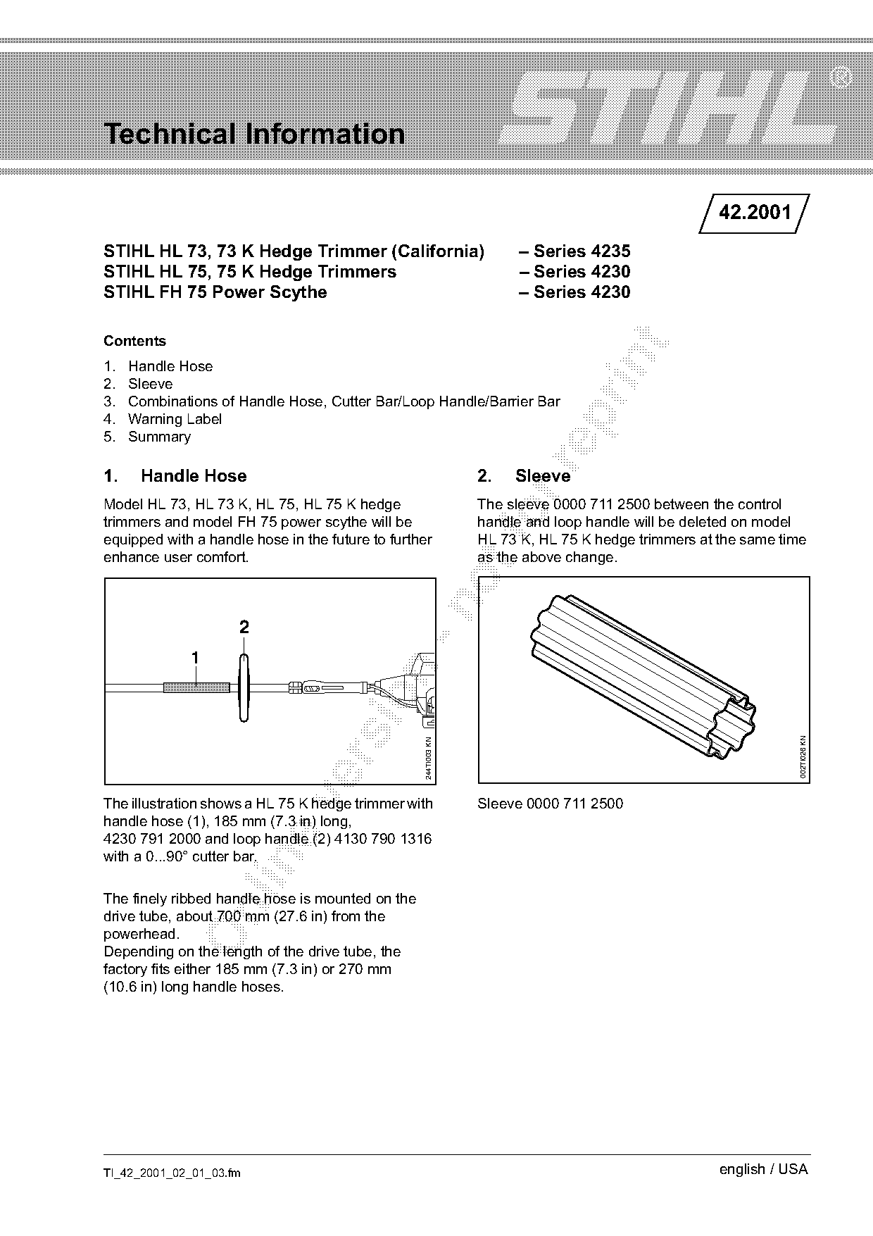
Model HL 73, HL 73 K, HL 75, HL 75 K hedge The sleeve 0000 711 2500 between the control
IssueTI 42/2001
Part changes (1)
| Was | Becomes | What the bulletin says |
|---|---|---|
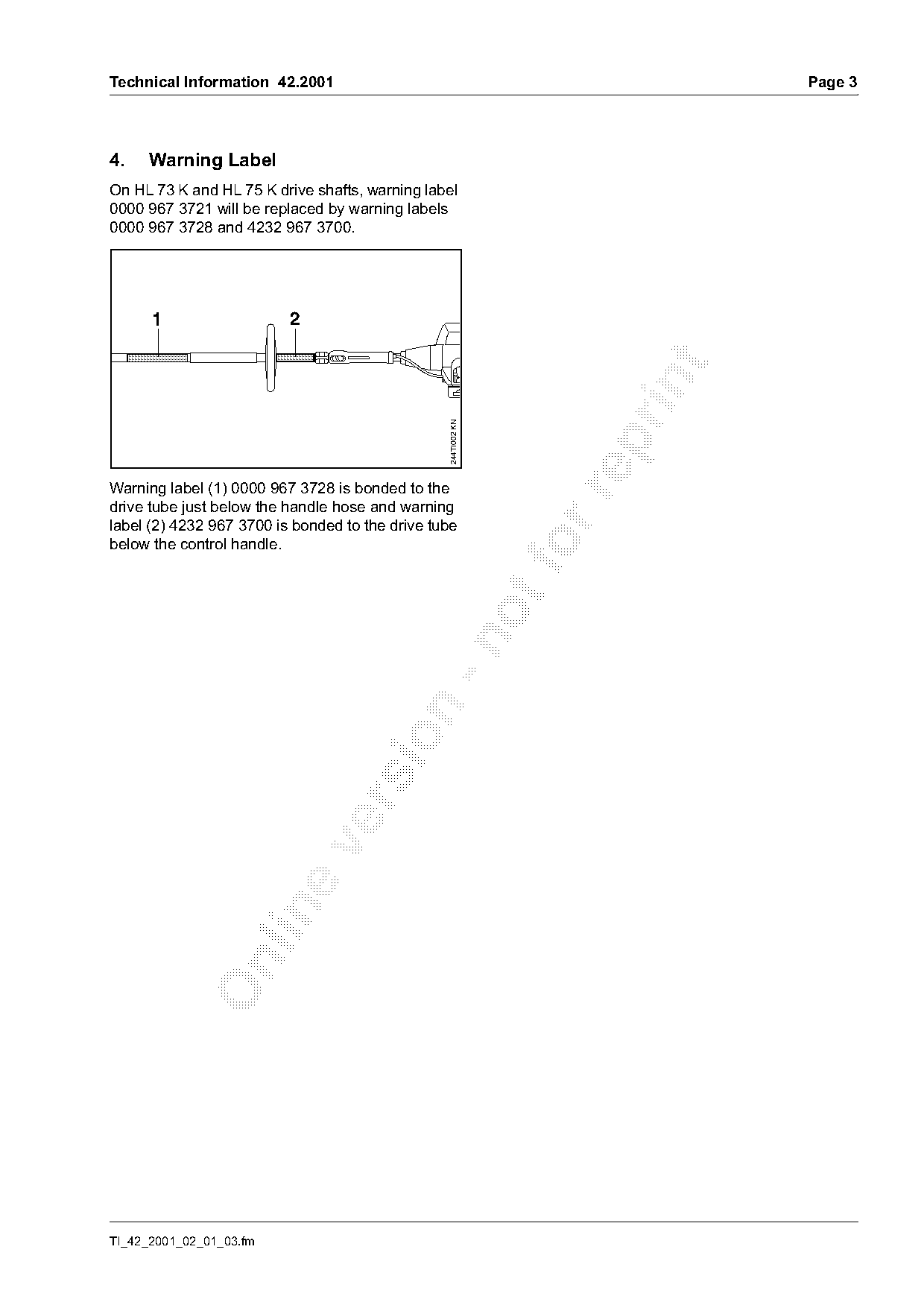
| 0000 967 3721 | 0000 967 3728 | Warning Label On HL 73 K and HL 75 K drive shafts, warning label 0000 967 3721 will be replaced by warning labels 0000 967 3728 and 4232 967 3700. |
Full text
Page 1 of 4
Text of page 1 — search, copy, screen readers
Technical Information

                                                                                                   42.2001
STIHL HL 73, 73 K Hedge Trimmer (California)                          – Series 4235
STIHL HL 75, 75 K Hedge Trimmers                                      – Series 4230
STIHL FH 75 Power Scythe                                              – Series 4230

Contents

1.   Handle Hose
2.   Sleeve
3.   Combinations of Handle Hose, Cutter Bar/Loop Handle/Barrier Bar

4.   Warning Label
5.   Summary

1.    Handle Hose                                               2.   Sleeve
Model HL 73, HL 73 K, HL 75, HL 75 K hedge                      The sleeve 0000 711 2500 between the control
trimmers and model FH 75 power scythe will be
equipped with a handle hose in the future to further
                                                                handle and loop handle will be deleted on model
                                                                HL 73 K, HL 75 K hedge trimmers at the same time
enhance user comfort.                                           as the above change.

                     2
              1

                                                                                                               002TI026 KN
                                                  244TI003 KN

The illustration shows a HL 75 K hedge trimmer with             Sleeve 0000 711 2500
handle hose (1), 185 mm (7.3 in) long,
4230 791 2000 and loop handle (2) 4130 790 1316
with a 0...90° cutter bar.

The finely ribbed handle hose is mounted on the

drive tube, about 700 mm (27.6 in) from the
powerhead.
Depending on the length of the drive tube, the
factory fits either 185 mm (7.3 in) or 270 mm
(10.6 in) long handle hoses.

TI_42_2001_02_01_03.fm                                                                             english / USA
Page 2 of 4
Text of page 2 — search, copy, screen readers
Page 2                                                                                    Technical Information 42.2001

3.    Combinations of Handle Hose,
      Cutter Bar/Loop Handle/Barrier Bar
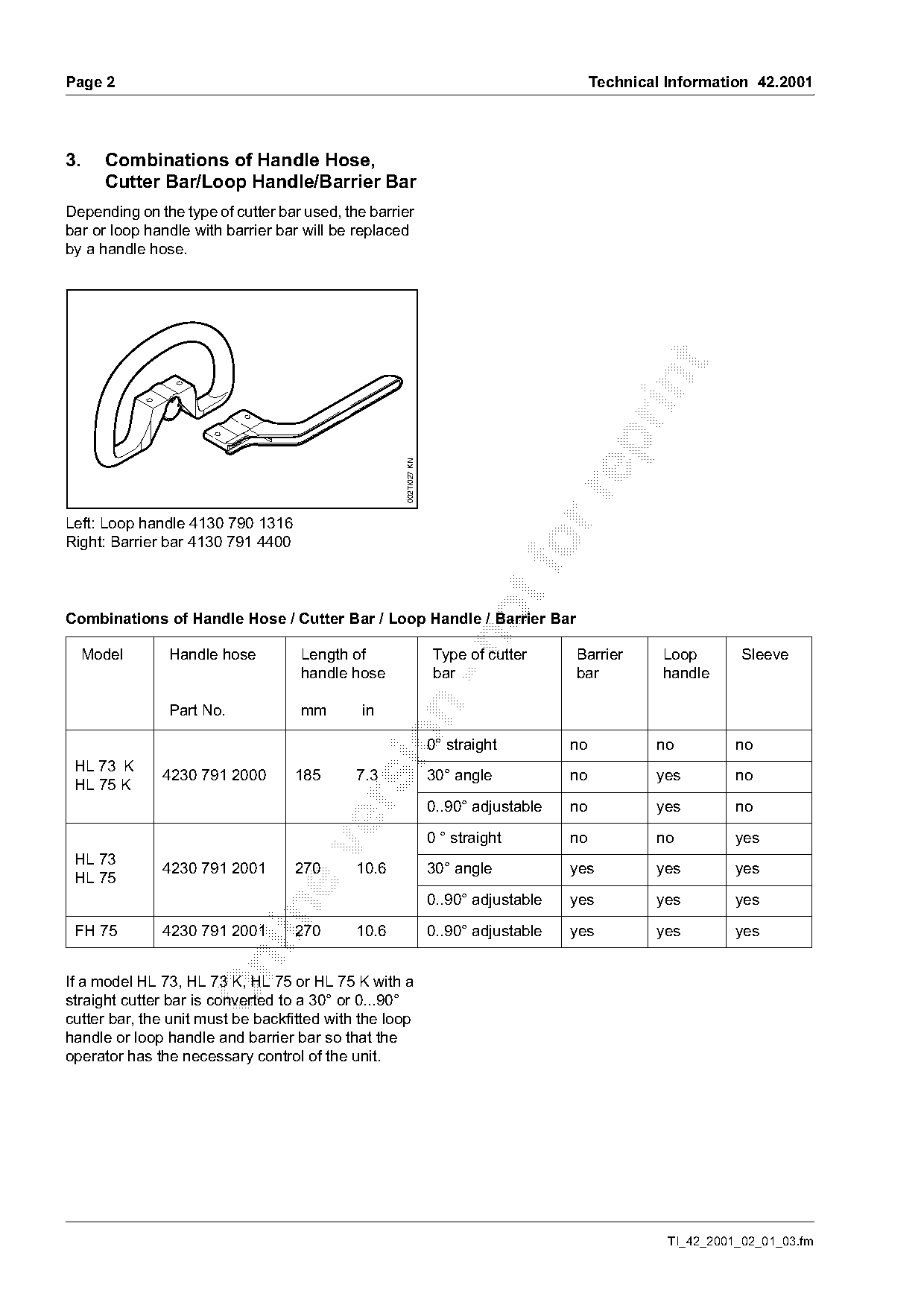
Depending on the type of cutter bar used, the barrier
bar or loop handle with barrier bar will be replaced
by a handle hose.

                                                   002TI027 KN

Left: Loop handle 4130 790 1316
Right: Barrier bar 4130 791 4400
Combinations of Handle Hose / Cutter Bar / Loop Handle / Barrier Bar

  Model        Handle hose         Length of                     Type of cutter      Barrier       Loop        Sleeve
                                   handle hose                   bar                 bar           handle

               Part No.            mm        in

                                                                 0° straight         no           no          no
 HL 73 K
              4230 791 2000        185      7.3                  30° angle           no           yes         no
 HL 75 K

                                                                 0..90° adjustable   no           yes         no

                                                                 0 ° straight        no           no          yes

 HL 73
              4230 791 2001        270      10.6                 30° angle           yes          yes         yes
 HL 75
                                                                 0..90° adjustable   yes          yes         yes

 FH 75        4230 791 2001        270      10.6                 0..90° adjustable   yes          yes         yes

If a model HL 73, HL 73 K, HL 75 or HL 75 K with a
straight cutter bar is converted to a 30° or 0...90°
cutter bar, the unit must be backfitted with the loop
handle or loop handle and barrier bar so that the
operator has the necessary control of the unit.

                                                                                                    TI_42_2001_02_01_03.fm
Page 3 of 4
Text of page 3 — search, copy, screen readers
Technical Information 42.2001                                                Page 3

4.   Warning Label
On HL 73 K and HL 75 K drive shafts, warning label
0000 967 3721 will be replaced by warning labels
0000 967 3728 and 4232 967 3700.

      1                   2

                                                 244TI002 KN

Warning label (1) 0000 967 3728 is bonded to the

drive tube just below the handle hose and warning
label (2) 4232 967 3700 is bonded to the drive tube
below the control handle.                                       fo

TI_42_2001_02_01_03.fm
Page 4 of 4
Text of page 4 — search, copy, screen readers
Page 4                                                                     Technical Information 42.2001

5.     Summary
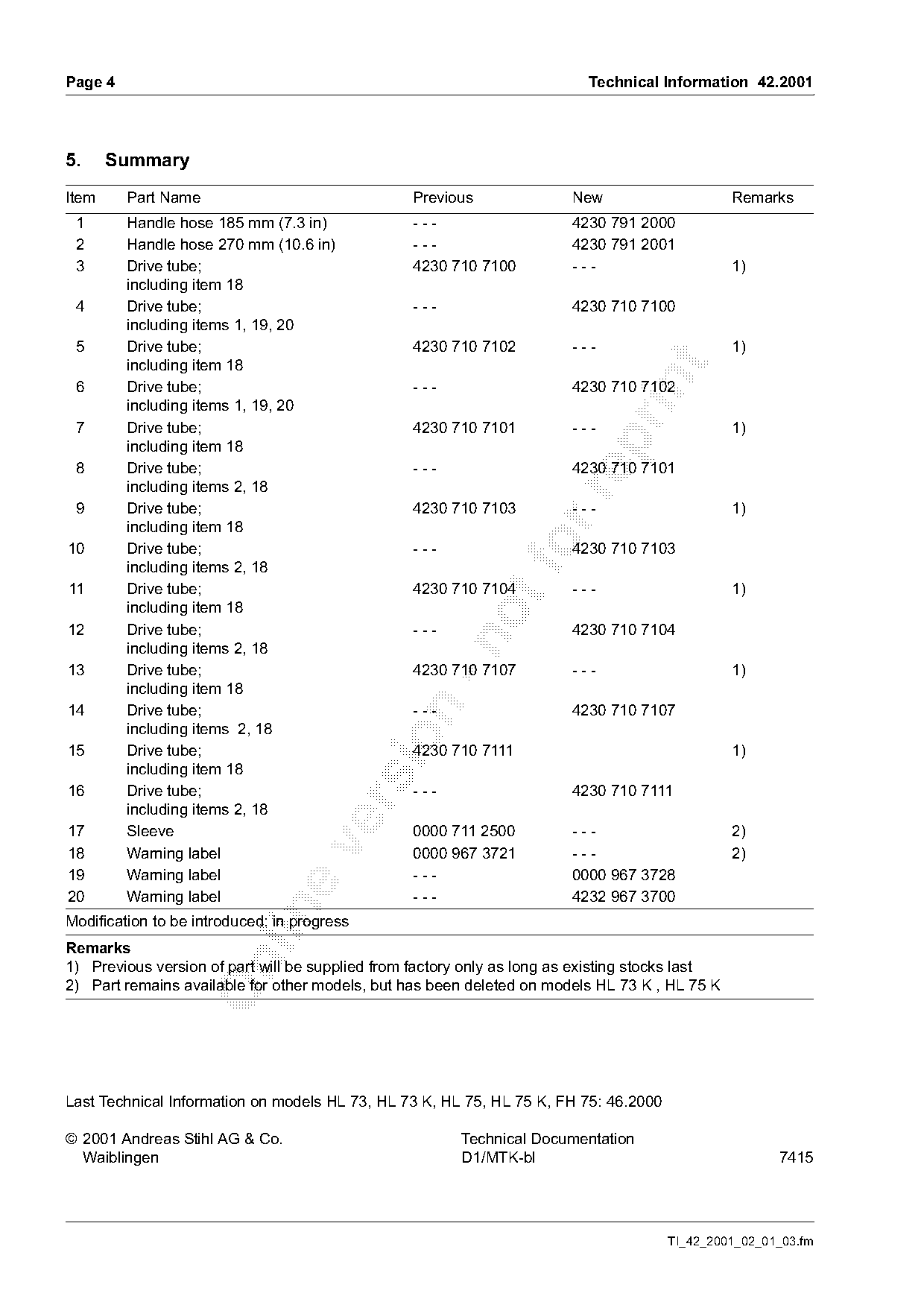
Item     Part Name                               Previous               New                      Remarks
 1       Handle hose 185 mm (7.3 in)             ---                    4230 791 2000
 2       Handle hose 270 mm (10.6 in)            ---                    4230 791 2001
 3       Drive tube;                             4230 710 7100          ---                      1)
         including item 18
 4       Drive tube;                             ---                    4230 710 7100
         including items 1, 19, 20
 5       Drive tube;                             4230 710 7102          ---                      1)
         including item 18

 6       Drive tube;                             ---                    4230 710 7102
         including items 1, 19, 20
 7       Drive tube;                             4230 710 7101          ---                      1)

         including item 18
 8       Drive tube;                             ---                    4230 710 7101
         including items 2, 18

 9       Drive tube;                             4230 710 7103          ---                      1)
         including item 18
10       Drive tube;
         including items 2, 18
                                                 ---             fo     4230 710 7103

11       Drive tube;                             4230 710 7104          ---                      1)
         including item 18
12       Drive tube;                             ---                    4230 710 7104

         including items 2, 18
13       Drive tube;                             4230 710 7107          ---                      1)
         including item 18
14       Drive tube;                             ---                    4230 710 7107

         including items 2, 18

15       Drive tube;                             4230 710 7111                                   1)
         including item 18
16       Drive tube;                             ---                    4230 710 7111

         including items 2, 18
17       Sleeve                                  0000 711 2500          ---                      2)

18       Warning label                           0000 967 3721          ---                      2)
19       Warning label                           ---                    0000 967 3728
20       Warning label                           ---                    4232 967 3700

Modification to be introduced: in progress
Remarks

1) Previous version of part will be supplied from factory only as long as existing stocks last
2) Part remains available for other models, but has been deleted on models HL 73 K , HL 75 K

Last Technical Information on models HL 73, HL 73 K, HL 75, HL 75 K, FH 75: 46.2000

© 2001 Andreas Stihl AG & Co.                           Technical Documentation
  Waiblingen                                            D1/MTK-bl                                     7415

                                                                                      TI_42_2001_02_01_03.fm
Most of these PDFs embed fonts with a shifted character map, so the text above was recovered rather than copied — read it as a faithful but imperfect transcription, and treat the page image above each block as the authority where the two disagree — the figures exist only there, because they are vector drawings that text extraction cannot keep.