Technical Information · issue 43 of 2001
New Sales Designations for 024, 026; Design Change
Model 026 Chainsaws – Series 1121
IssueTI 43/2001
Engine family 1121
Part changes (4)
| Was | Becomes | What the bulletin says |
|---|---|---|
| 1121 350 0828 | 1121 350 0829 | The previous tank housing 1121 350 0828 will be replaced by the new version 1121 350 0829. |
| 1121 350 5802 | 0000 350 5800 | 1 Tank Vent The previous tank vent 1121 350 5802 will be replaced by the new version 0000 350 5800. |
| 1121 020 2112 | 1121 020 2117 | fo Crankcase The previous crankcase 1121 020 2112 for the 026 will be replaced by the new version 1121 020 2117. |
| 1121 121 2905 | 1121 120 2900 | 2 = Choke shutter The previous choke shutter 1121 121 2905 in the air filter has been replaced by the new choke shutter 1121 120 2900 to further improve starting behavior. |
Full text
Page 1 of 8
Text of page 1 — search, copy, screen readers
Technical Information

                                                                                              43.2001
Model 026 Chainsaws – Series 1121

Contents
1. New Sales Designationfor 026
2. Design Change

3. Tank Caps

4. Tank housing
5. Crankcase
6. Fan Housing (round nameplate)

7. Wiring (wiring harness, crankcase, cylinder, shroud)
8. Air Filter
9. Spare Parts

10. Summary

1.    New Sales Designation
      for 026

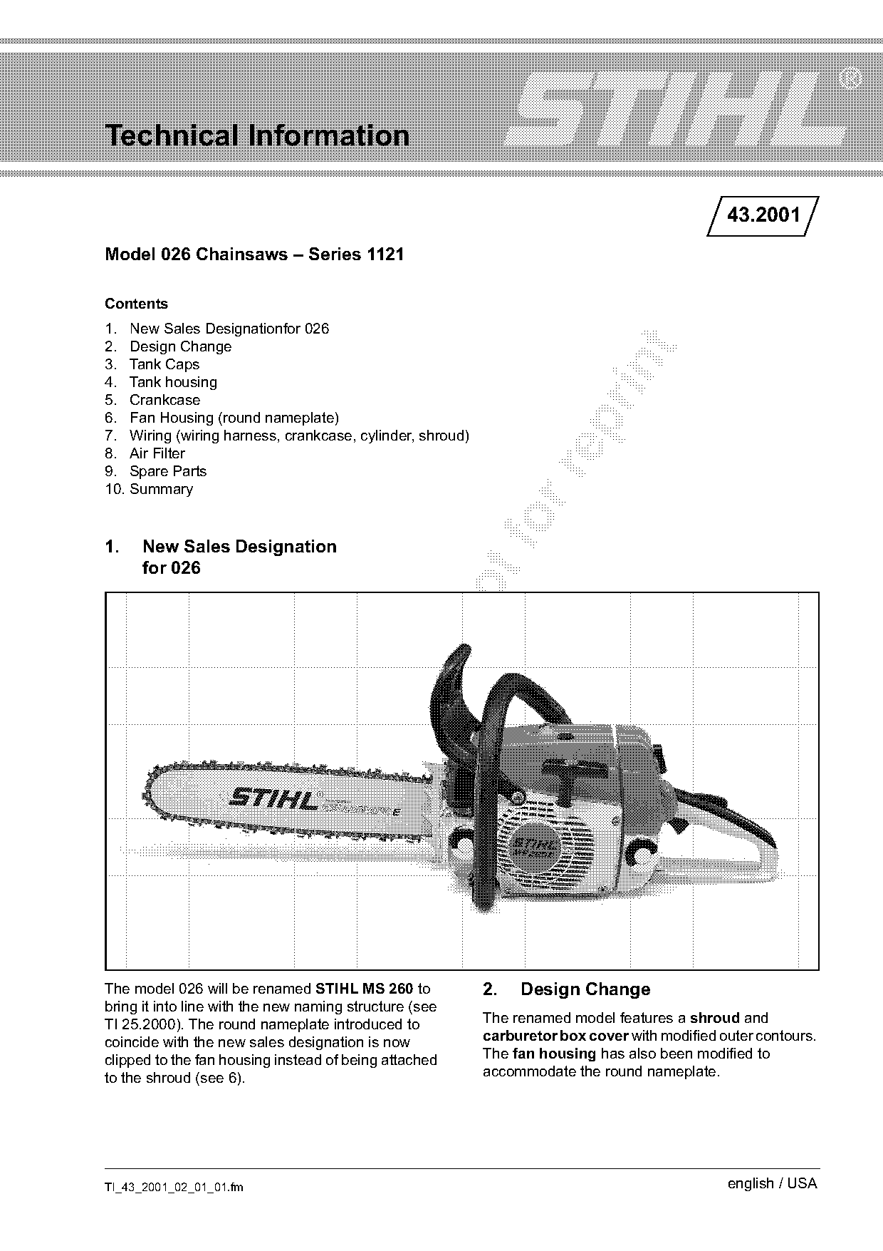
The model 026 will be renamed STIHL MS 260 to             2.   Design Change
bring it into line with the new naming structure (see
TI 25.2000). The round nameplate introduced to            The renamed model features a shroud and
coincide with the new sales designation is now            carburetor box cover with modified outer contours.
clipped to the fan housing instead of being attached      The fan housing has also been modified to
to the shroud (see 6).                                    accommodate the round nameplate.

TI_43_2001_02_01_01.fm                                                                        english / USA
Page 2 of 8
Text of page 2 — search, copy, screen readers
Page 2                                                                                  Technical Information 43.2001

2.1   Shroud

                                                    172TI001 KN

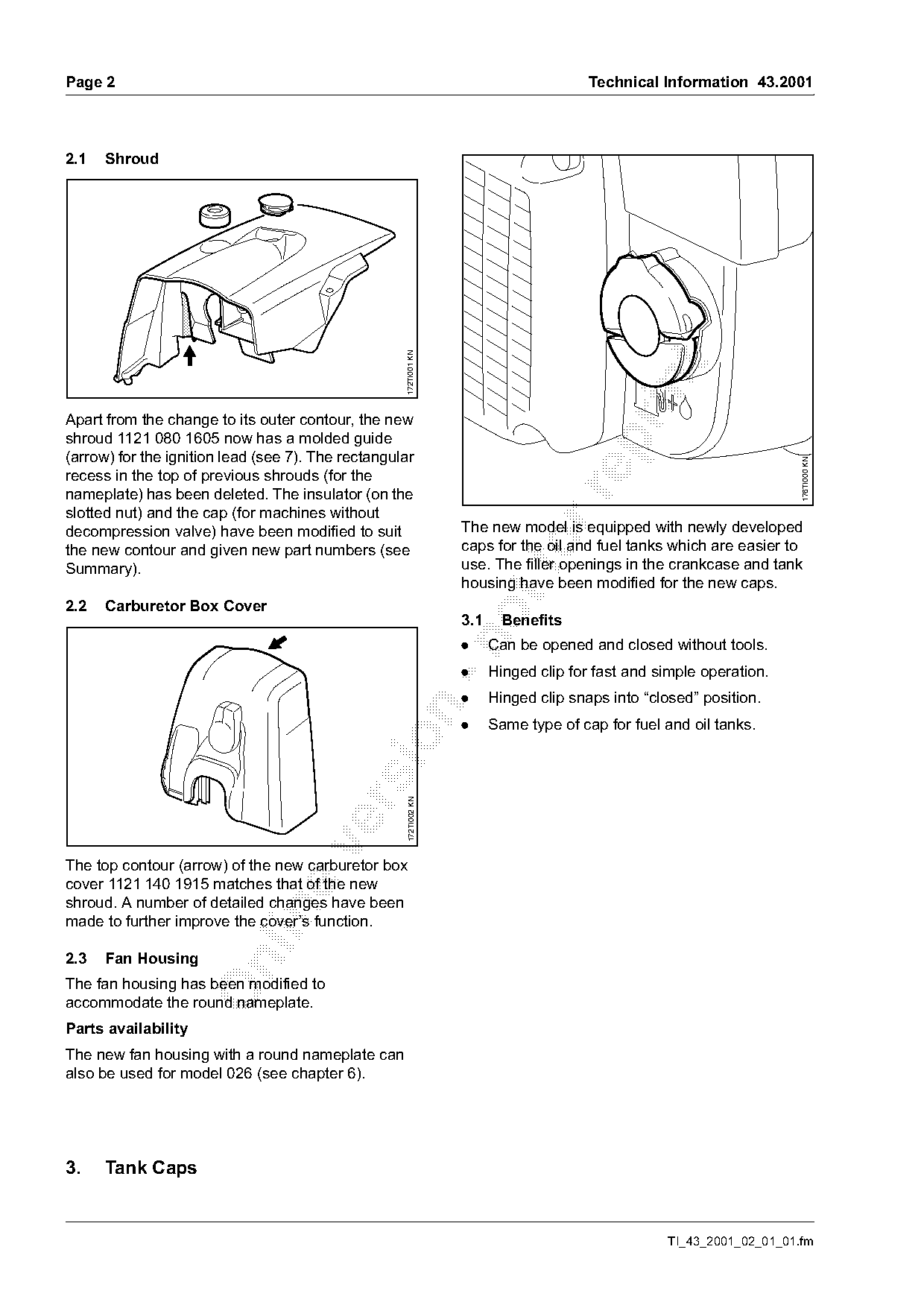
Apart from the change to its outer contour, the new
shroud 1121 080 1605 now has a molded guide

(arrow) for the ignition lead (see 7). The rectangular

                                                                                                                        176TI000 KN
recess in the top of previous shrouds (for the
nameplate) has been deleted. The insulator (on the

slotted nut) and the cap (for machines without
decompression valve) have been modified to suit                    The new model is equipped with newly developed
the new contour and given new part numbers (see
Summary).
                                                                   caps for the oil and fuel tanks which are easier to
                                                                   use. The filler openings in the crankcase and tank
                                                                   housing have been modified for the new caps.
2.2   Carburetor Box Cover
                                                                   3.1    Benefits

                                                                   .     Can be opened and closed without tools.
                                                                   .     Hinged clip for fast and simple operation.
                                                                   .     Hinged clip snaps into “closed” position.

                                                                   .     Same type of cap for fuel and oil tanks.
                                                     172TI002 KN

The top contour (arrow) of the new carburetor box
cover 1121 140 1915 matches that of the new
shroud. A number of detailed changes have been

made to further improve the cover’s function.

2.3   Fan Housing

The fan housing has been modified to
accommodate the round nameplate.
Parts availability
The new fan housing with a round nameplate can
also be used for model 026 (see chapter 6).

3.    Tank Caps

                                                                                                    TI_43_2001_02_01_01.fm
Page 3 of 8
Text of page 3 — search, copy, screen readers
Technical Information 43.2001                                                                                 Page 3

3.2    Operation

3.2.1 Opening                                                   3.2.2 Closing

                                                                                                                    176TI003 KN
                                                  176TI001 KN

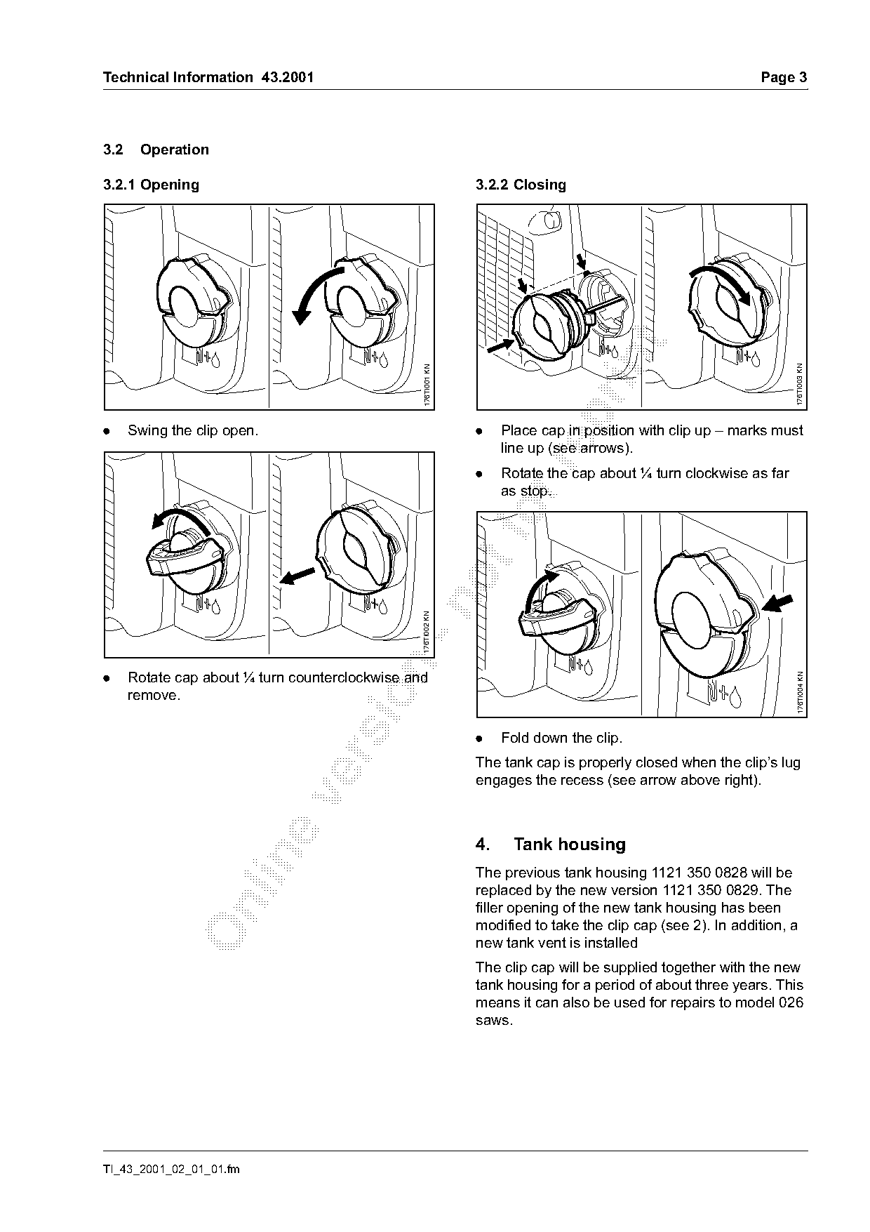
.     Swing the clip open.                                      .    Place cap in position with clip up – marks must
                                                                     line up (see arrows).

                                                                .    Rotate the cap about ¼ turn clockwise as far
                                                                     as stop.
                                               -n176TI002 KN

.     Rotate cap about ¼ turn counterclockwise and

                                                                                                                     176TI004 KN
      remove.

                                                                .    Fold down the clip.

                                                                The tank cap is properly closed when the clip’s lug
                                                                engages the recess (see arrow above right).

                                                                4.    Tank housing

                                                                The previous tank housing 1121 350 0828 will be
                                                                replaced by the new version 1121 350 0829. The
                                                                filler opening of the new tank housing has been

                                                                modified to take the clip cap (see 2). In addition, a
                                                                new tank vent is installed
                                                                The clip cap will be supplied together with the new
                                                                tank housing for a period of about three years. This
                                                                means it can also be used for repairs to model 026
                                                                saws.

TI_43_2001_02_01_01.fm
Page 4 of 8
Text of page 4 — search, copy, screen readers
Page 4                                                                                Technical Information 43.2001

4.1       Tank Vent
The previous tank vent 1121 350 5802 will be
replaced by the new version 0000 350 5800.
                                                                    1                      4
4.1.1 Construction of tank vent 0000 350 5800


                                                                                                                       176TI007 KN
                                           4

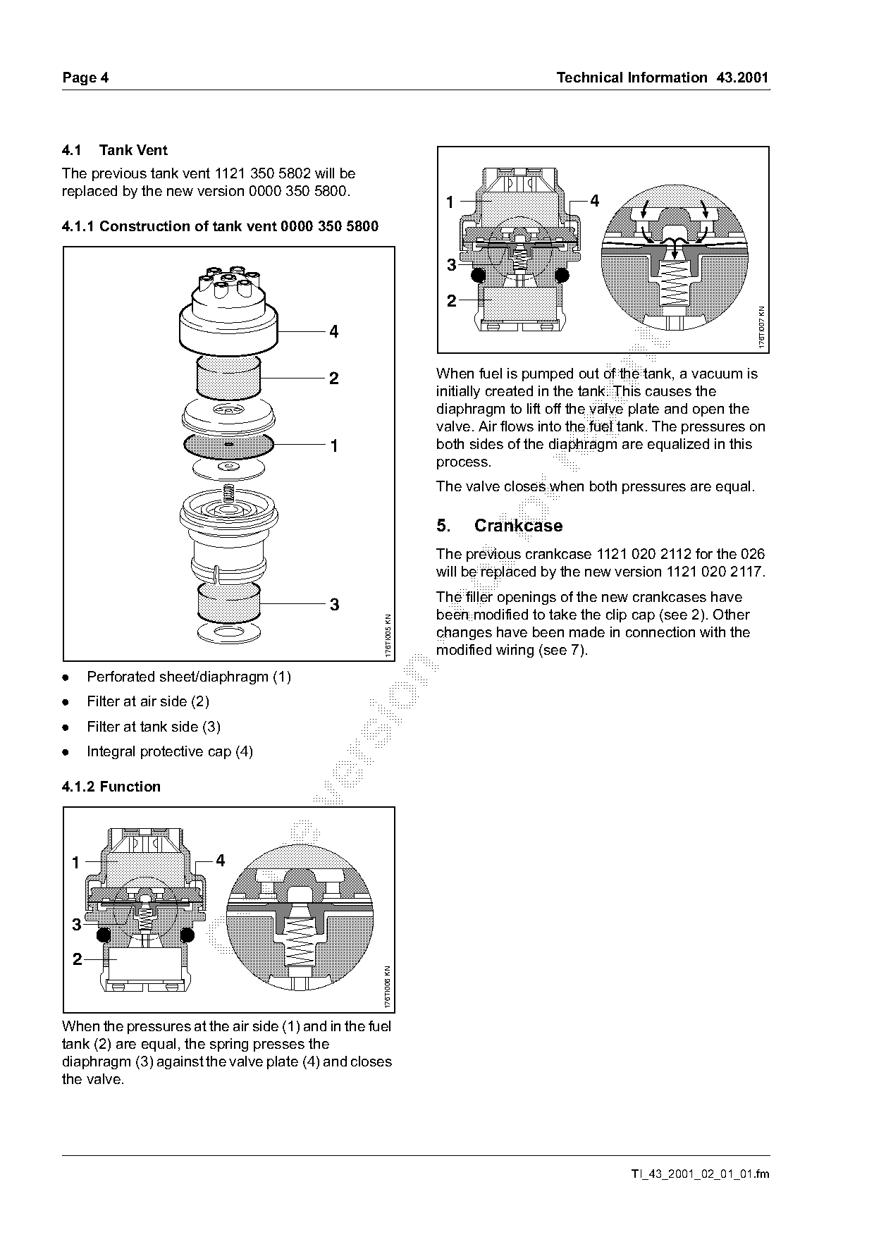
                                           2                       When fuel is pumped out of the tank, a vacuum is
                                                                   initially created in the tank. This causes the
                                                                   diaphragm to lift off the valve plate and open the

                                                                   valve. Air flows into the fuel tank. The pressures on
                                           1                       both sides of the diaphragm are equalized in this
                                                                   process.

                                                                   The valve closes when both pressures are equal.

                                                                   5.      fo
                                                                         Crankcase
                                                                   The previous crankcase 1121 020 2112 for the 026
                                                                   will be replaced by the new version 1121 020 2117.
                                                                   The filler openings of the new crankcases have
                                           3

                                                                   been modified to take the clip cap (see 2). Other
                                                     176TI005 KN

                                                                   changes have been made in connection with the
                                                                   modified wiring (see 7).

.       Perforated sheet/diaphragm (1)

.       Filter at air side (2)
.       Filter at tank side (3)
.       Integral protective cap (4)

4.1.2 Function

    1                            4

    3
    2
                                                    176TI006 KN

When the pressures at the air side (1) and in the fuel
tank (2) are equal, the spring presses the
diaphragm (3) against the valve plate (4) and closes
the valve.

                                                                                                  TI_43_2001_02_01_01.fm
Page 5 of 8
Text of page 5 — search, copy, screen readers
Technical Information 43.2001                                                                                   Page 5

6.   Fan Housing (round nameplate)                               7.    Wiring (wiring harness, crankcase,
                                                                       cylinder, shroud)
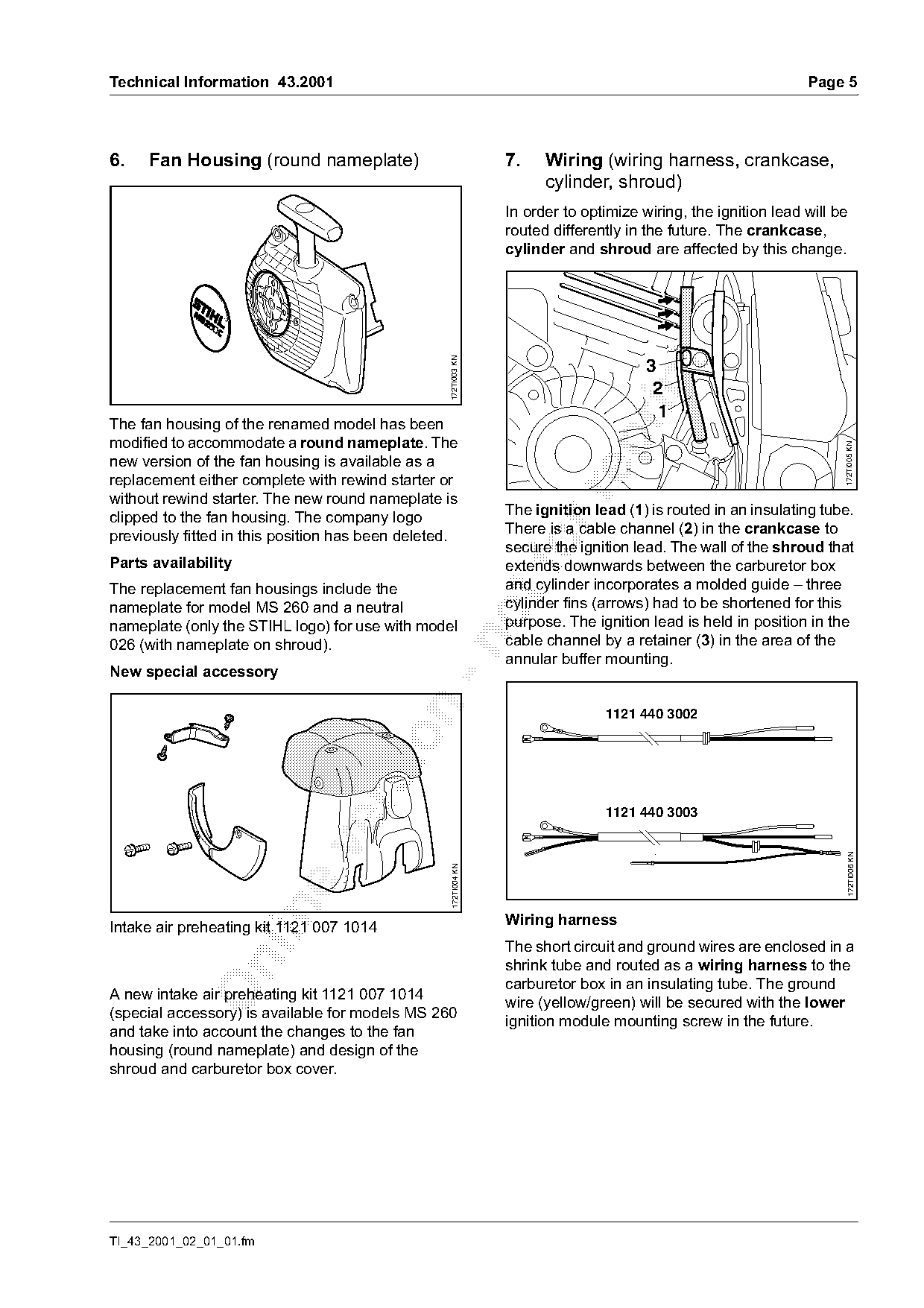
                                                                 In order to optimize wiring, the ignition lead will be
                                                                 routed differently in the future. The crankcase,
                                                                 cylinder and shroud are affected by this change.

                                                  172TI003 KN
                                                                                       3

                                                                                        2
                                                                                         1
The fan housing of the renamed model has been

modified to accommodate a round nameplate. The

                                                                                                                      172TI005 KN
new version of the fan housing is available as a
replacement either complete with rewind starter or

without rewind starter. The new round nameplate is
clipped to the fan housing. The company logo                     The ignition lead (1) is routed in an insulating tube.
previously fitted in this position has been deleted.             There is a cable channel (2) in the crankcase to

Parts availability
                                                                 secure the ignition lead. The wall of the shroud that
                                                                 extends downwards between the carburetor box
The replacement fan housings include the                         and cylinder incorporates a molded guide – three
nameplate for model MS 260 and a neutral                         cylinder fins (arrows) had to be shortened for this
nameplate (only the STIHL logo) for use with model               purpose. The ignition lead is held in position in the
                                                                 cable channel by a retainer (3) in the area of the

026 (with nameplate on shroud).
                                                                 annular buffer mounting.
New special accessory

                                                                                1121 440 3002

                                                                                1121 440 3003

                                                                                                                       172TI006 KN
                                                   172TI004 KN

Intake air preheating kit 1121 007 1014                          Wiring harness
                                                                 The short circuit and ground wires are enclosed in a

                                                                 shrink tube and routed as a wiring harness to the
                                                                 carburetor box in an insulating tube. The ground
A new intake air preheating kit 1121 007 1014
                                                                 wire (yellow/green) will be secured with the lower
(special accessory) is available for models MS 260
                                                                 ignition module mounting screw in the future.
and take into account the changes to the fan
housing (round nameplate) and design of the
shroud and carburetor box cover.

TI_43_2001_02_01_01.fm
Page 6 of 8
Text of page 6 — search, copy, screen readers
Page 6                                                                       Technical Information 43.2001

8.    Air Filter

                              2
                          1

                                                     172TI007 KN

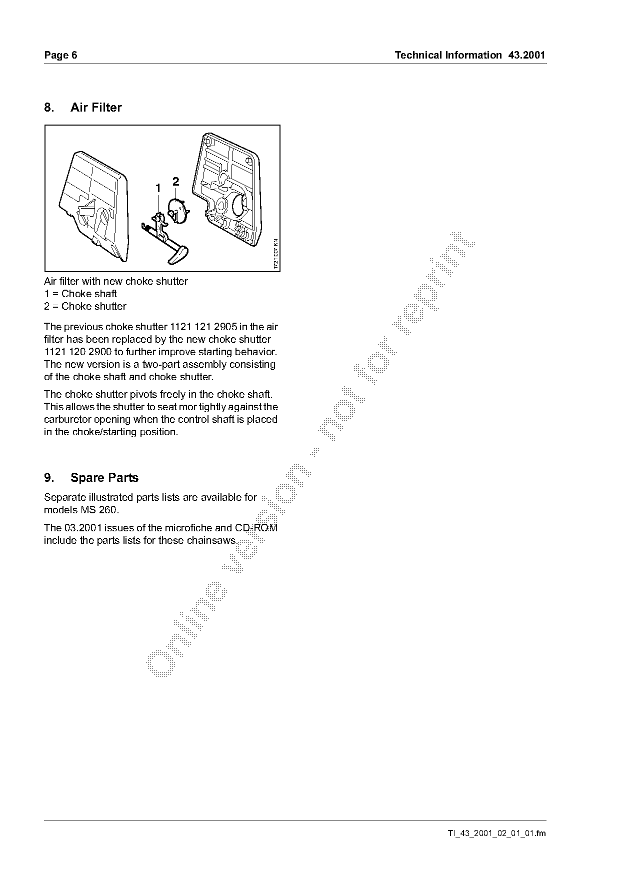
Air filter with new choke shutter
1 = Choke shaft

2 = Choke shutter
The previous choke shutter 1121 121 2905 in the air

filter has been replaced by the new choke shutter
1121 120 2900 to further improve starting behavior.
The new version is a two-part assembly consisting                       fo
of the choke shaft and choke shutter.
The choke shutter pivots freely in the choke shaft.
This allows the shutter to seat mor tightly against the
carburetor opening when the control shaft is placed

in the choke/starting position.

9.    Spare Parts

Separate illustrated parts lists are available for
models MS 260.
The 03.2001 issues of the microfiche and CD-ROM

include the parts lists for these chainsaws.

                                                                                       TI_43_2001_02_01_01.fm
Page 7 of 8
Text of page 7 — search, copy, screen readers
Technical Information 43.2001                                                               Page 7

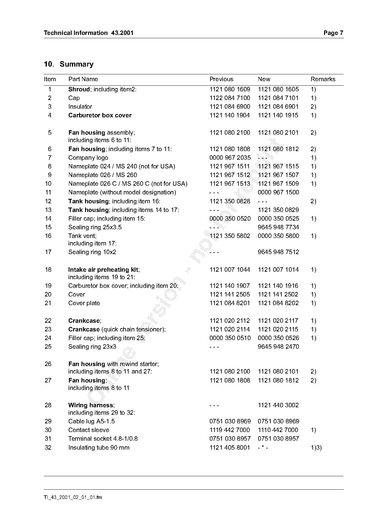
10. Summary
Item     Part Name                                   Previous        New             Remarks
 1       Shroud; including item2:                    1121 080 1609   1121 080 1605   1)
 2       Cap                                         1122 084 7100   1121 084 7101   1)
 3       Insulator                                   1121 084 6900   1121 084 6901   2)
 4       Carburetor box cover                        1121 140 1904   1121 140 1915   1)

 5       Fan housing assembly;                       1121 080 2100   1121 080 2101   2)
         including items 6 to 11:

 6       Fan housing; including items 7 to 11:       1121 080 1808   1121 080 1812   2)

 7       Company logo                                0000 967 2035   ---             1)
 8       Nameplate 024 / MS 240 (not for USA)        1121 967 1511   1121 967 1515   1)
 9       Nameplate 026 / MS 260                      1121 967 1512   1121 967 1507   1)

10       Nameplate 026 C / MS 260 C (not for USA)    1121 967 1513   1121 967 1509   1)
11       Nameplate (without model designation)       ---             0000 967 1500

12       Tank housing; including item 16:            1121 350 0828   ---             2)
13       Tank housing; including items 14 to 17:     ---             1121 350 0829
14
15
         Filler cap; including item 15:
         Sealing ring 25x3.5
                                                     0000 350 0520
                                                     ---
                                                                     0000 350 0525
                                                                     9645 948 7734
                                                                                     1)

16       Tank vent;                                  1121 350 5802   0000 350 5800   1)
         including item 17:
17       Sealing ring 10x2                           ---             9645 948 7512

18       Intake air preheating kit;                  1121 007 1044   1121 007 1014   1)
         including items 19 to 21:

19       Carburetor box cover; including item 20:    1121 140 1907   1121 140 1916   1)
20       Cover                                       1121 141 2505   1121 141 2502   1)

21       Cover plate                                 1121 084 8201   1121 084 8202   1)

22       Crankcase;                                  1121 020 2112   1121 020 2117   1)

23       Crankcase (quick chain tensioner);          1121 020 2114   1121 020 2115   1)
24       Filler cap; including item 25:              0000 350 0510   0000 350 0526   1)

25       Sealing ring 23x3                           ---             9645 948 2470

26       Fan housing with rewind starter;

         including items 8 to 11 and 27:             1121 080 2100   1121 080 2101   2)
27       Fan housing;                                1121 080 1808   1121 080 1812   2)

         including items 8 to 11

28       Wiring harness;                             ---             1121 440 3002
         including items 29 to 32:
29       Cable lug A5-1.5                            0751 030 8969   0751 030 8969
30       Contact sleeve                              1119 442 7000   1110 442 7000   1)
31       Terminal socket 4.8-1/0.8                   0751 030 8957   0751 030 8957
32       Insulating tube 90 mm                       1121 405 8001   -*-             1)3)

TI_43_2001_02_01_01.fm
Page 8 of 8
Text of page 8 — search, copy, screen readers
Page 8                                                                         Technical Information 43.2001

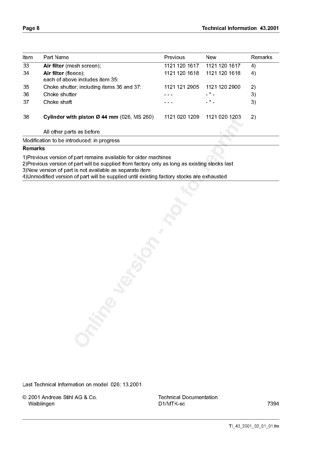
Item     Part Name                                            Previous          New                 Remarks
33       Air filter (mesh screen);                            1121 120 1617     1121 120 1617       4)
34       Air filter (fleece);                                 1121 120 1618     1121 120 1618       4)
         each of above includes item 35:
35       Choke shutter; including items 36 and 37:            1121 121 2905     1121 120 2900       2)
36       Choke shutter                                        ---               -*-                 3)
37       Choke shaft                                          ---               -*-                 3)

38       Cylinder with piston Ø 44 mm (026, MS 260)           1121 020 1209     1121 020 1203       2)

         All other parts as before
Modification to be introduced: in progress
Remarks

1)Previous version of part remains available for older machines
2)Previous version of part will be supplied from factory only as long as existing stocks last

3)New version of part is not available as separate item
4)Unmodified version of part will be supplied until existing factory stocks are exhausted

Last Technical Information on model 026: 13.2001

© 2001 Andreas Stihl AG & Co.                               Technical Documentation
  Waiblingen                                                D1/MTK-sc                                      7394

                                                                                           TI_43_2001_02_01_01.fm
Most of these PDFs embed fonts with a shifted character map, so the text above was recovered rather than copied — read it as a faithful but imperfect transcription, and treat the page image above each block as the authority where the two disagree — the figures exist only there, because they are vector drawings that text extraction cannot keep.