Technical Information · issue 50 of 2001
New Electric Saw
IssueTI 50/2001
Full text
Page 1 of 3
Text of page 1 — search, copy, screen readers
Technical Information

                                                                                             50.2001
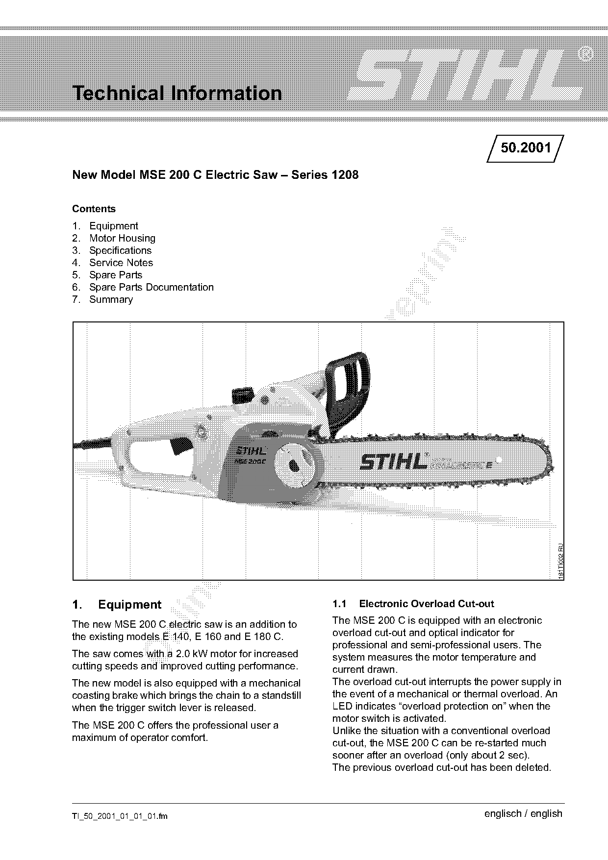
New Model MSE 200 C Electric Saw – Series 1208

Contents
1.   Equipment
2.   Motor Housing

3.   Specifications

4.   Service Notes
5.   Spare Parts
6.   Spare Parts Documentation

7.   Summary

1.    Equipment                                         1.1   Electronic Overload Cut-out
The new MSE 200 C electric saw is an addition to        The MSE 200 C is equipped with an electronic
                                                        overload cut-out and optical indicator for

the existing models E 140, E 160 and E 180 C.
                                                        professional and semi-professional users. The
The saw comes with a 2.0 kW motor for increased         system measures the motor temperature and
cutting speeds and improved cutting performance.        current drawn.
The new model is also equipped with a mechanical        The overload cut-out interrupts the power supply in
coasting brake which brings the chain to a standstill   the event of a mechanical or thermal overload. An
when the trigger switch lever is released.              LED indicates “overload protection on” when the
                                                        motor switch is activated.
The MSE 200 C offers the professional user a
                                                        Unlike the situation with a conventional overload
maximum of operator comfort.
                                                        cut-out, the MSE 200 C can be re-started much
                                                        sooner after an overload (only about 2 sec).
                                                        The previous overload cut-out has been deleted.

TI_50_2001_01_01_01.fm                                                                   englisch / english
Page 2 of 3
Text of page 2 — search, copy, screen readers
Page 2                                                                             Technical Information 50.2001

1.2   Chain Braking System                                      3.2     Motor Speeds (Chain Sprocket) with
A mechanical coasting brake is integrated in the                        Cutting Attachment
inertia-tripped chain braking system. It brings the             Under load                    5,900 rpm
chain to a standstill when the user releases the                Off load                      6,400 rpm
trigger switch and locks the brake drum in position
while the saw is idle.                                          3.3     Noise and Vibration Data
The brake band is disengaged from the brake drum
when the trigger switch is squeezed.                            Sound pressure level Lp(1m)
                                                                to prEN 50144-2-13 1)         92 dB(A)
1.3   Starting Current Limiter                                  Sound power level Lw
                                                                to prEN 50144-2-13 1)         105 dB(A)
The starting current limiter helps prevent the

machine jerking during switch-on. This enables the              Vibration measurement

saw chain to be positioned accurately for the cut.              to prEN 50144-2-13 2)
Normal mains fuses (16 A) are not overloaded.                   Left handle                   4.4 m/s²
                                                                Right handle                  5.8 m/s²

2.    Motor Housing                                             1)
                                                                     off load
                                                                2)
                                                                     under load

                                                                3.4     Miscellaneous
                                                                Oil tank capacity         0.2 l (200 cm3)
                                                                Weight
                                                                without bar and chain,
                          1                                     without connecting
                                                                cable                     3.6 kg
                                                                Length of connecting

                                                                cable                     1.7 m
                                                  181TI000 KN

                                                                3.5     Cutting Attachment

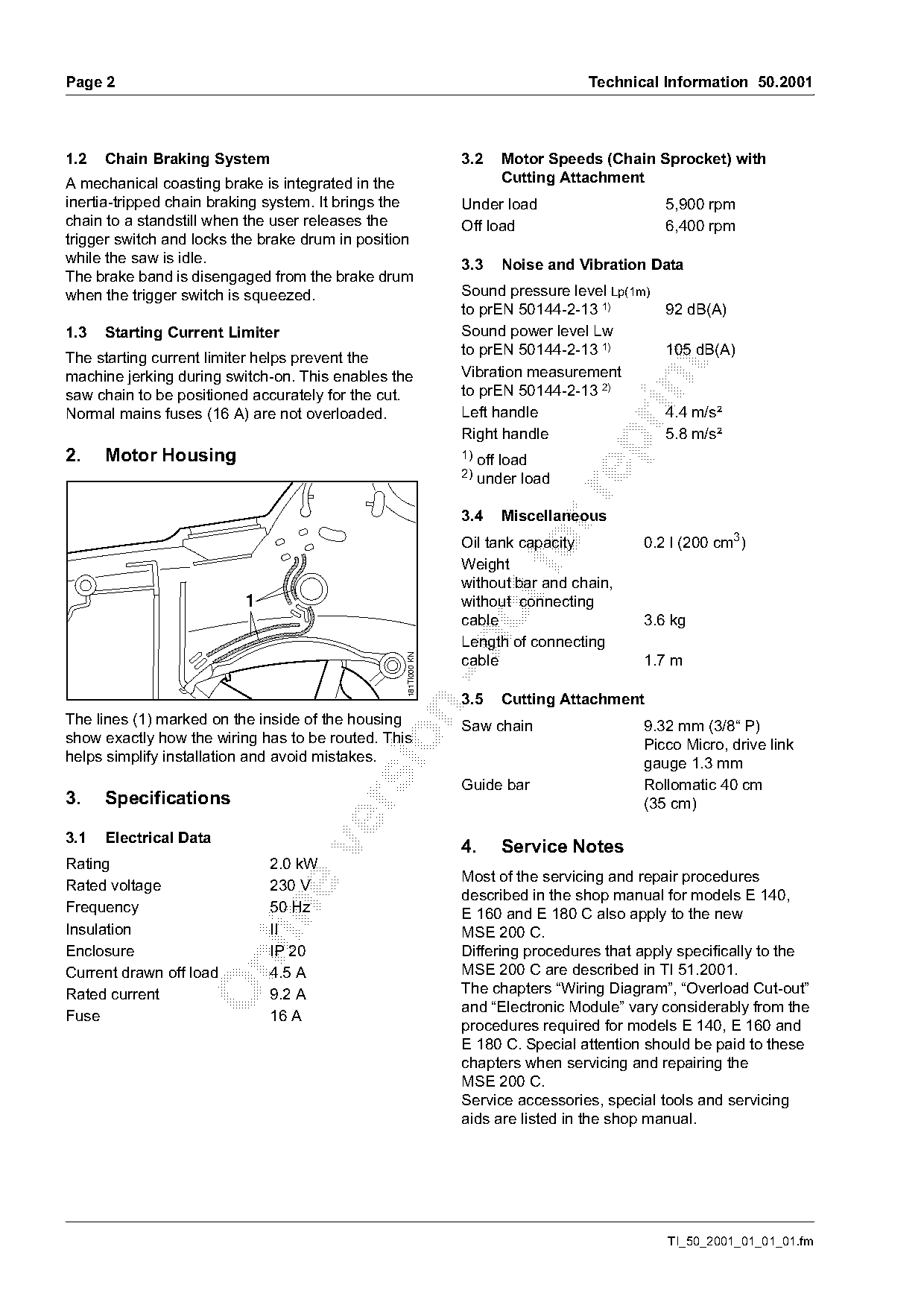
The lines (1) marked on the inside of the housing               Saw chain                 9.32 mm (3/8“ P)
show exactly how the wiring has to be routed. This

                                                                                          Picco Micro, drive link
helps simplify installation and avoid mistakes.                                           gauge 1.3 mm
                                                                Guide bar                 Rollomatic 40 cm
3.    Specifications                                                                      (35 cm)

3.1   Electrical Data
                                                                4.      Service Notes

Rating                        2.0 kW
                                                                Most of the servicing and repair procedures
Rated voltage                 230 V
                                                                described in the shop manual for models E 140,
Frequency                     50 Hz

                                                                E 160 and E 180 C also apply to the new
Insulation                    II                                MSE 200 C.
Enclosure                     IP 20                             Differing procedures that apply specifically to the

Current drawn off load        4.5 A                             MSE 200 C are described in TI 51.2001.
Rated current                 9.2 A                             The chapters “Wiring Diagram”, “Overload Cut-out”
                                                                and “Electronic Module” vary considerably from the
Fuse                          16 A
                                                                procedures required for models E 140, E 160 and
                                                                E 180 C. Special attention should be paid to these
                                                                chapters when servicing and repairing the
                                                                MSE 200 C.
                                                                Service accessories, special tools and servicing
                                                                aids are listed in the shop manual.

                                                                                              TI_50_2001_01_01_01.fm
Page 3 of 3
Text of page 3 — search, copy, screen readers
Technical Information 50.2001                                                             Page 3

5.     Spare Parts
New spare parts for MSE 200 C
The MSE 200 C is based on models E 140, E 160
and E 180 C. Different parts in the new machine are
described in the ’Summary’.

6.     Spare Parts Documentation
The parts list for the MSE 200 C has been integrated
in the parts list for models MSE 140, MSE 160 and
MSE 180 C integriert.

The next issues of the microfiche and CD-ROM

(01.2002) include the parts list.

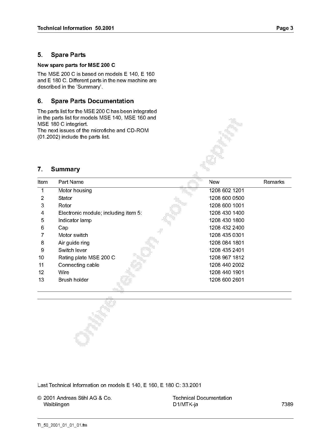
7.     Summary

Item     Part Name                                                    New             Remarks
 1
 2
         Motor housing
         Stator
                                                        fo            1208 602 1201
                                                                      1208 600 0500
 3       Rotor                                                        1208 600 1001
 4       Electronic module; including item 5:                         1208 430 1400

 5       Indicator lamp                                               1208 430 1800
 6       Cap                                                          1208 432 2400
 7       Motor switch                                                 1208 435 0301
 8       Air guide ring                                               1208 084 1801

 9       Switch lever                                                 1208 435 2401

10       Rating plate MSE 200 C                                       1208 967 1812
11       Connecting cable                                             1208 440 2002
12       Wire                                                         1208 440 1901

13       Brush holder                                                 1208 600 2601

Last Technical Information on models E 140, E 160, E 180 C: 33.2001

© 2001 Andreas Stihl AG & Co.                          Technical Documentation
  Waiblingen                                           D1/MTK-ja                           7389

TI_50_2001_01_01_01.fm
Most of these PDFs embed fonts with a shifted character map, so the text above was recovered rather than copied — read it as a faithful but imperfect transcription, and treat the page image above each block as the authority where the two disagree — the figures exist only there, because they are vector drawings that text extraction cannot keep.