Technical Information · issue 51 of 2001
Service notes
IssueTI 51/2001
Full text
Page 1 of 12
Text of page 1 — search, copy, screen readers
Technical Information

                                                                                           51.2001
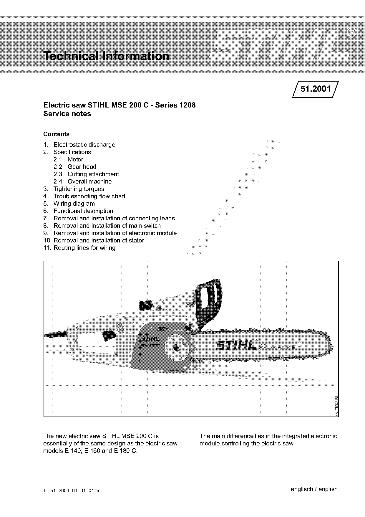
Electric saw STIHL MSE 200 C - Series 1208
Service notes

Contents
1. Electrostatic discharge

2. Specifications
    2.1 Motor
    2.2 Gear head
    2.3 Cutting attachment

    2.4 Overall machine
3. Tightening torques

4. Troubleshooting flow chart
5. Wiring diagram
6. Functional description
7. Removal and installation of connecting leads
8. Removal and installation of main switch
9. Removal and installation of electronic module
10. Removal and installation of stator
11. Routing lines for wiring

The new electric saw STIHL MSE 200 C is              The main difference lies in the integrated electronic
essentially of the same design as the electric saw   module controlling the electric saw.
models E 140, E 160 and E 180 C.

TI_51_2001_01_01_01.fm                                                                  englisch / english
Page 2 of 12
Text of page 2 — search, copy, screen readers
Page 2                                                                      Technical Information 51.2001

This gives rise to the following additional              1.   Electrostatic discharge
differences:
                                                         Electronically controlled machines are considered
.   New troubleshooting flow chart                       to be subject to "electrostatic risks", meaning that
.   New wiring diagram                                   the electronic components (in this case the
                                                         electronic module) may be destroyed by
.   Different functional description
                                                         electrostatic discharges, for instance when touched.
.   Changed wiring connection to the main switch         Special precautions are necessary to prevent this
.   Overload protection is integrated into the           happening.
    electronic module which receives the necessary       When carrying out any repairs, it is therefore
    data from a temperature sensor in the motor          essential to ensure that the person carrying out the
                                                         repairs is connected to ground potential or is

.   No overload switch

                                                         grounded before touching any parts. This can be
.   New overload indication by an LED                    achieved, for instance, by using a ground strap or
.   Routing lines for wiring inside the housing          touching a grounded object (e.g. water pipe or
                                                         heating pipe of metal).

.   Partly modified or new service notes                 The same also applies when handing over the
                                                         electronic module to another person.

The service manual for models E 140, E 160 and
E 180 C can be consulted as the basis for repairing
the new electric saw STIHL MSE 200 C.
All changes and new developments are described in
this Technical Information.
The instructions and particularly the safety
instructions in the foreword of the aforementioned

service manual for the E 140, E 160 and E 180 C
models must be noted without fail. The mains
connector must always be unplugged before
starting any work.

To ensure correct operation of the machine, it is

essential that the wiring be carefully routed
inside the housing. This is described in detail in
this Technical Information.

The specified national safety regulations and the
safety instructions in the User Manual must be

observed if the chainsaw has to be started up during
maintenance or repair work on the machine.

                                                                                       TI_51_2001_01_01_01.fm
Page 3 of 12
Text of page 3 — search, copy, screen readers
Technical Information 51.2001                                                                        Page 3

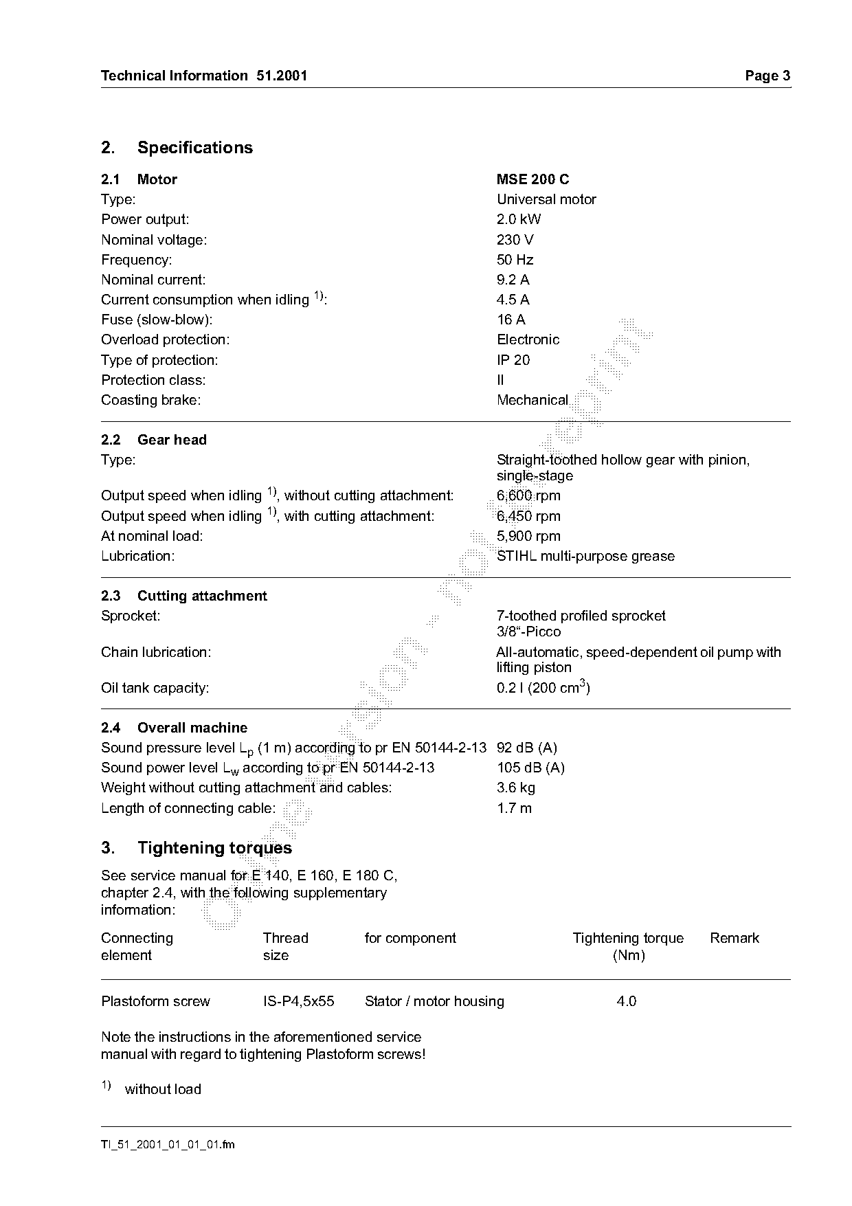
2.    Specifications
2.1 Motor                                                    MSE 200 C
Type:                                                        Universal motor
Power output:                                                2.0 kW
Nominal voltage:                                             230 V
Frequency:                                                   50 Hz
Nominal current:                                             9.2 A
Current consumption when idling 1):                          4.5 A
Fuse (slow-blow):                                            16 A

Overload protection:                                         Electronic

Type of protection:                                          IP 20
Protection class:                                            II
Coasting brake:                                              Mechanical

2.2 Gear head

Type:                                                        Straight-toothed hollow gear with pinion,
                                                             single-stage
Output speed when idling 1), without cutting attachment:     6,600 rpm
Output speed when idling 1), with cutting attachment:
                                                           fo6,450 rpm
At nominal load:                                             5,900 rpm
Lubrication:                                                 STIHL multi-purpose grease

2.3 Cutting attachment
Sprocket:                                                    7-toothed profiled sprocket
                                                             3/8“-Picco
Chain lubrication:                                           All-automatic, speed-dependent oil pump with

                                                             lifting piston

Oil tank capacity:                                           0.2 l (200 cm3)

2.4 Overall machine

Sound pressure level Lp (1 m) according to pr EN 50144-2-13 92 dB (A)
Sound power level Lw according to pr EN 50144-2-13          105 dB (A)

Weight without cutting attachment and cables:               3.6 kg
Length of connecting cable:                                 1.7 m

3.    Tightening torques
See service manual for E 140, E 160, E 180 C,

chapter 2.4, with the following supplementary
information:

Connecting               Thread          for component                   Tightening torque     Remark
element                  size                                                  (Nm)

Plastoform screw         IS-P4,5x55      Stator / motor housing                 4.0

Note the instructions in the aforementioned service
manual with regard to tightening Plastoform screws!

1)   without load

TI_51_2001_01_01_01.fm
Page 4 of 12
Text of page 4 — search, copy, screen readers
Page 4                                                                                Technical Information 51.2001

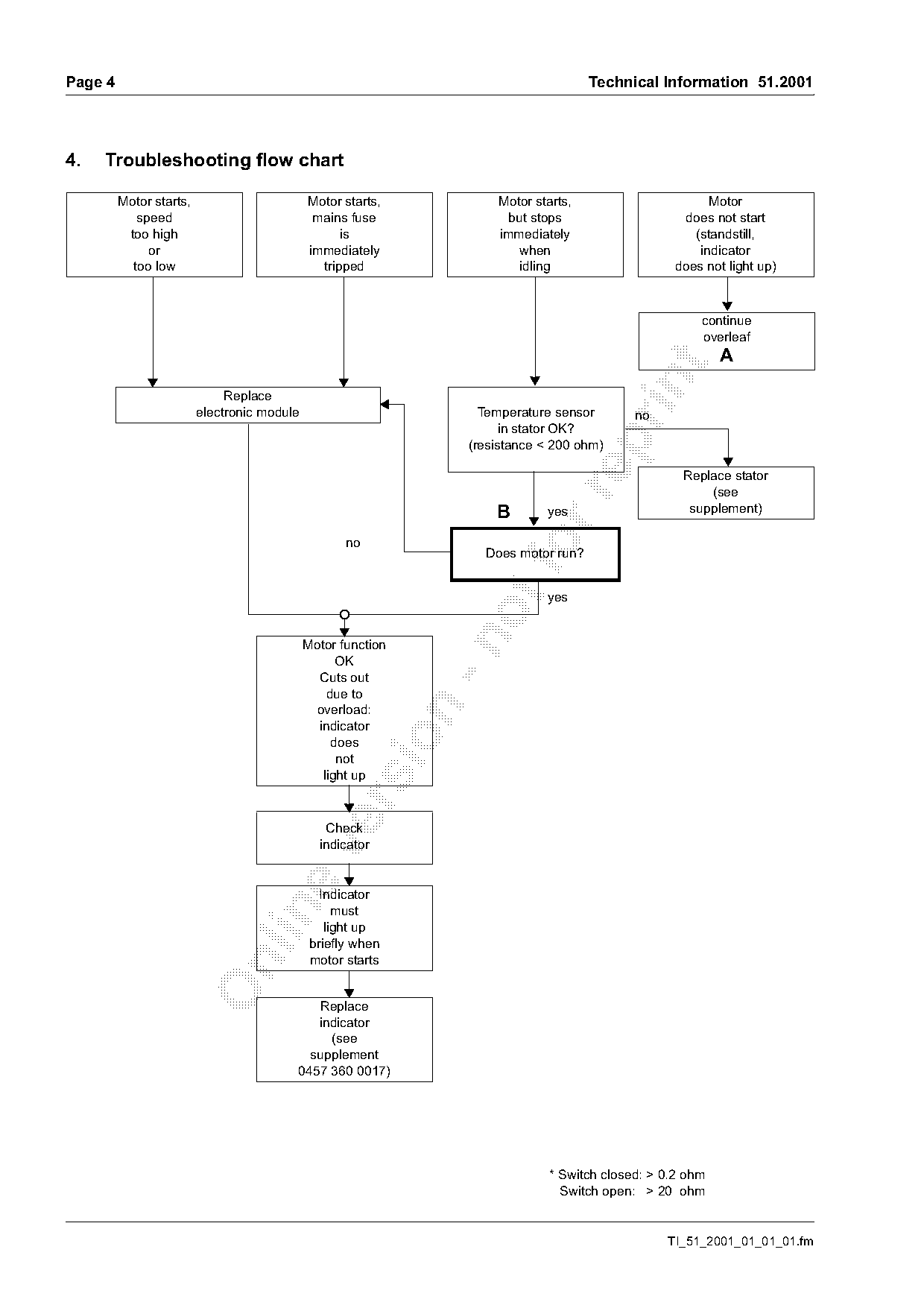
4.   Troubleshooting flow chart

         Motor starts,                       Motor starts,            Motor starts,                      Motor
            speed                             mains fuse                but stops                   does not start
          too high                                 is                 immediately                     (standstill,
              or                             immediately                 when                          indicator
           too low                             tripped                    idling                   does not light up)

                                                                                                        continue
                                                                                                        overleaf
                                                                                                            A

                              Replace
                         electronic module                          Temperature sensor       no
                                                                        in stator OK?

                                                                  (resistance < 200 ohm)

                                                                                                     Replace stator
                                                                                                         (see

                                                                      B       yes                     supplement)

                                                                    Does motor run?

                                                                              yes

                                             Motor function
                                                   OK
                                               Cuts out
                                                 due to

                                              overload:
                                               indicator

                                                  does
                                                light up

                                                Check
                                               indicator

                                                Indicator

                                                   must
                                                 light up
                                              briefly when
                                              motor starts

                                            Replace
                                            indicator
                                              (see
                                           supplement
                                         0457 360 0017)

                                                                               * Switch closed: > 0.2 ohm
                                                                               == Switch open: > 20 ohm

                                                                                                  TI_51_2001_01_01_01.fm
Page 5 of 12
Text of page 5 — search, copy, screen readers
Technical Information 51.2001                                                        Page 5

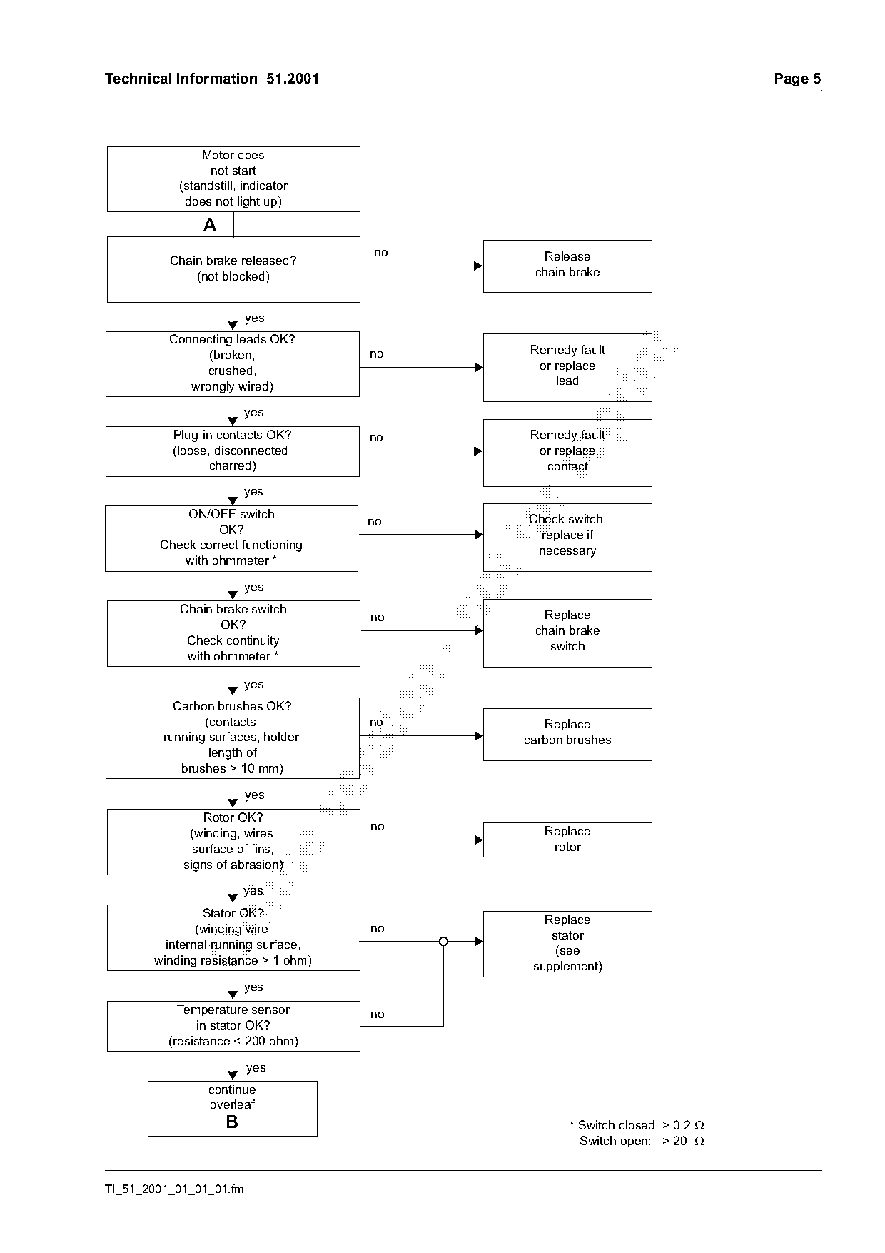
               Motor does
                not start
           (standstill, indicator
            does not light up)
                A
                                      no              Release
          Chain brake released?
              (not blocked)                          chain brake

                         yes
          Connecting leads OK?
                                                    Remedy fault

                (broken,              no
                                                     or replace

               crushed,
             wrongly wired)                             lead

                         yes

          Plug-in contacts OK?        no            Remedy fault
          (loose, disconnected,                      or replace
                 charred)                             contact

                        yes
            ON/OFF switch
                 OK?
        Check correct functioning
                                                fo  Check switch,
                                                      replace if
                                                     necessary
           with ohmmeter *
                         yes
            Chain brake switch

                                      no              Replace
                   OK?                               chain brake
             Check continuity                          switch
             with ohmmeter *

                         yes
           Carbon brushes OK?

                (contacts,            no            Replace
         running surfaces, holder,               carbon brushes
                 length of
            brushes > 10 mm)

                         yes

                Rotor OK?
                                      no              Replace
             (winding, wires,
              surface of fins,                         rotor
            signs of abrasion)

                        yes
                Stator OK?                            Replace

               (winding wire,         no
                                                       stator
         internal running surface,                      (see
       winding resistance > 1 ohm)                  supplement)
                        yes
            Temperature sensor        no
                in stator OK?
          (resistance < 200 ohm)

                         yes
                 continue
                 overleaf
                    B                                     * Switch closed: > 0.2 τ
                                                          == Switch open: > 20 τ

TI_51_2001_01_01_01.fm
Page 6 of 12
Text of page 6 — search, copy, screen readers
Page 6                                                                   Technical Information 51.2001

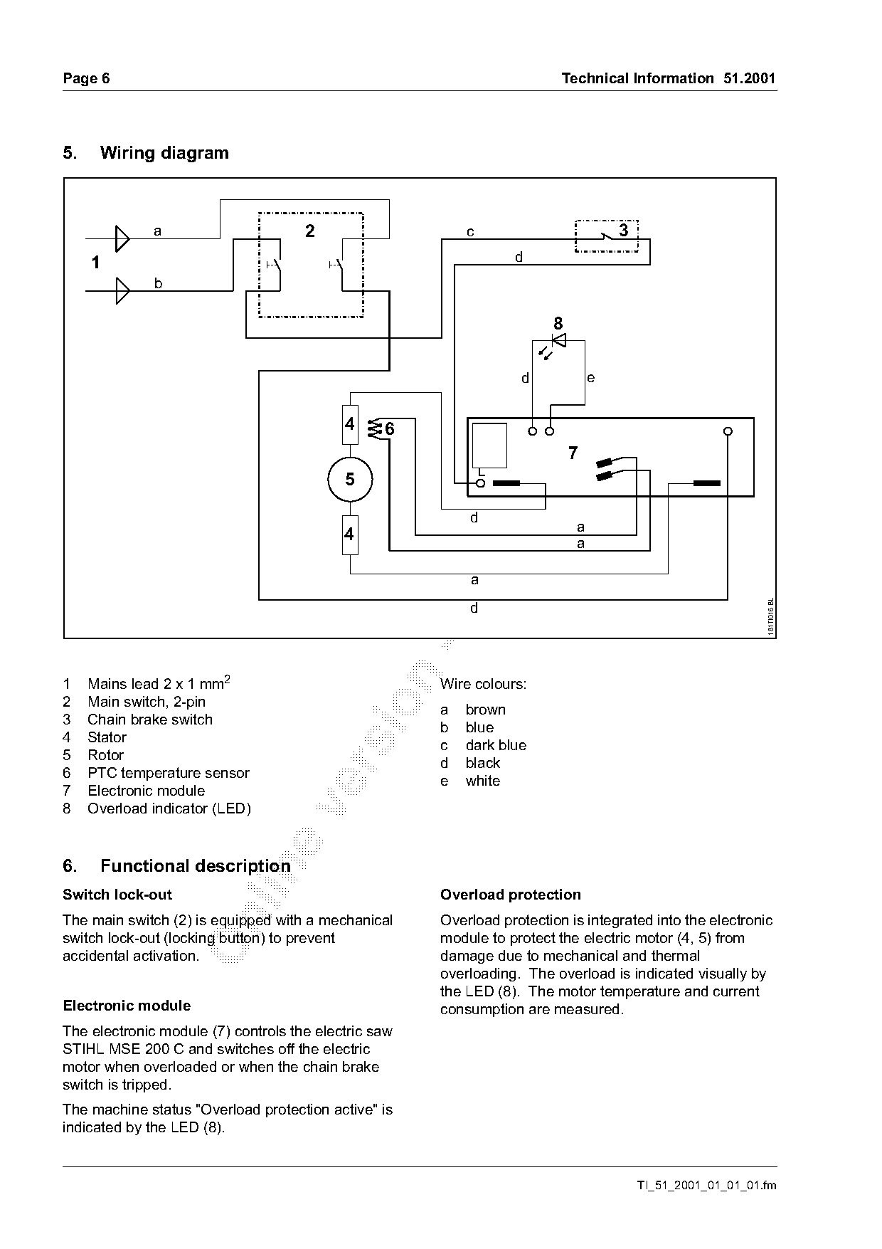
5.    Wiring diagram

              a                      2                    c                         3
     1                                                            d
              b


                                                                  d             e

                                           4     6
                                                                            7


                                           4
                                                          d
                                                                  fo        a
                                                                            a
                                                          a

                                                                                                            181TI016 BL
                                                          d

1    Mains lead 2 x 1 mm2                             Wire colours:
2    Main switch, 2-pin

                                                      a   brown
3    Chain brake switch
                                                      b   blue
4    Stator
                                                      c   dark blue
5    Rotor
                                                      d   black

6    PTC temperature sensor
                                                      e   white
7    Electronic module
8    Overload indicator (LED)

6.    Functional description

Switch lock-out                                       Overload protection
The main switch (2) is equipped with a mechanical     Overload protection is integrated into the electronic

switch lock-out (locking button) to prevent           module to protect the electric motor (4, 5) from
accidental activation.                                damage due to mechanical and thermal
                                                      overloading. The overload is indicated visually by
                                                      the LED (8). The motor temperature and current
Electronic module                                     consumption are measured.
The electronic module (7) controls the electric saw
STIHL MSE 200 C and switches off the electric
motor when overloaded or when the chain brake
switch is tripped.
The machine status "Overload protection active" is
indicated by the LED (8).

                                                                                        TI_51_2001_01_01_01.fm
Page 7 of 12
Text of page 7 — search, copy, screen readers
Technical Information 51.2001                                                                       Page 7

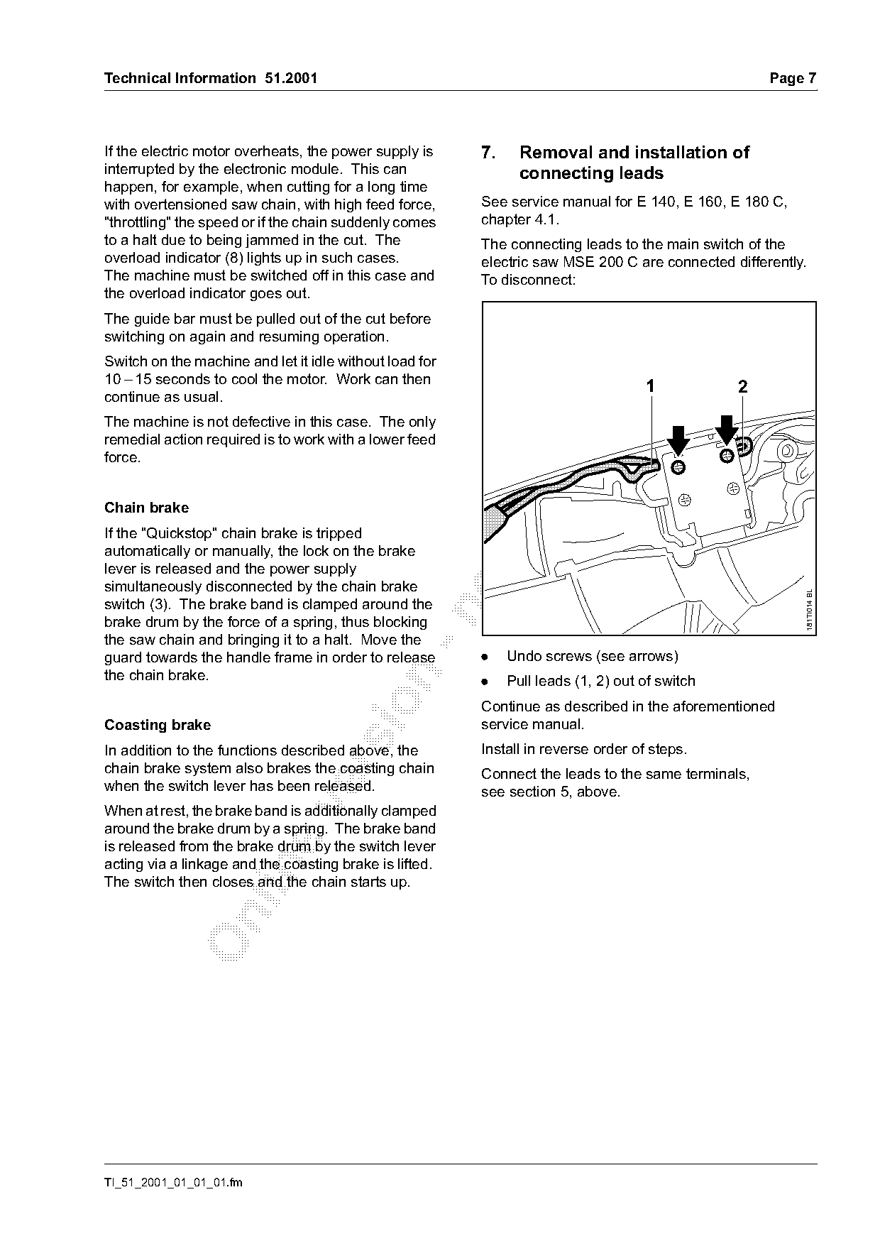
If the electric motor overheats, the power supply is     7.     Removal and installation of
interrupted by the electronic module. This can                  connecting leads
happen, for example, when cutting for a long time
with overtensioned saw chain, with high feed force,      See service manual for E 140, E 160, E 180 C,
"throttling" the speed or if the chain suddenly comes    chapter 4.1.
to a halt due to being jammed in the cut. The            The connecting leads to the main switch of the
overload indicator (8) lights up in such cases.          electric saw MSE 200 C are connected differently.
The machine must be switched off in this case and        To disconnect:
the overload indicator goes out.
The guide bar must be pulled out of the cut before
switching on again and resuming operation.

Switch on the machine and let it idle without load for

10 – 15 seconds to cool the motor. Work can then
                                                                                    1           2
continue as usual.

The machine is not defective in this case. The only
remedial action required is to work with a lower feed
force.

Chain brake
If the "Quickstop" chain brake is tripped
automatically or manually, the lock on the brake
lever is released and the power supply
simultaneously disconnected by the chain brake

                                                                                                         181TI014 BL
switch (3). The brake band is clamped around the

brake drum by the force of a spring, thus blocking
the saw chain and bringing it to a halt. Move the
guard towards the handle frame in order to release       .    Undo screws (see arrows)
the chain brake.

                                                         .    Pull leads (1, 2) out of switch

                                                         Continue as described in the aforementioned
Coasting brake                                           service manual.
In addition to the functions described above, the        Install in reverse order of steps.

chain brake system also brakes the coasting chain        Connect the leads to the same terminals,
when the switch lever has been released.                 see section 5, above.

When at rest, the brake band is additionally clamped
around the brake drum by a spring. The brake band
is released from the brake drum by the switch lever
acting via a linkage and the coasting brake is lifted.

The switch then closes and the chain starts up.

TI_51_2001_01_01_01.fm
Page 8 of 12
Text of page 8 — search, copy, screen readers
Page 8                                                                                 Technical Information 51.2001

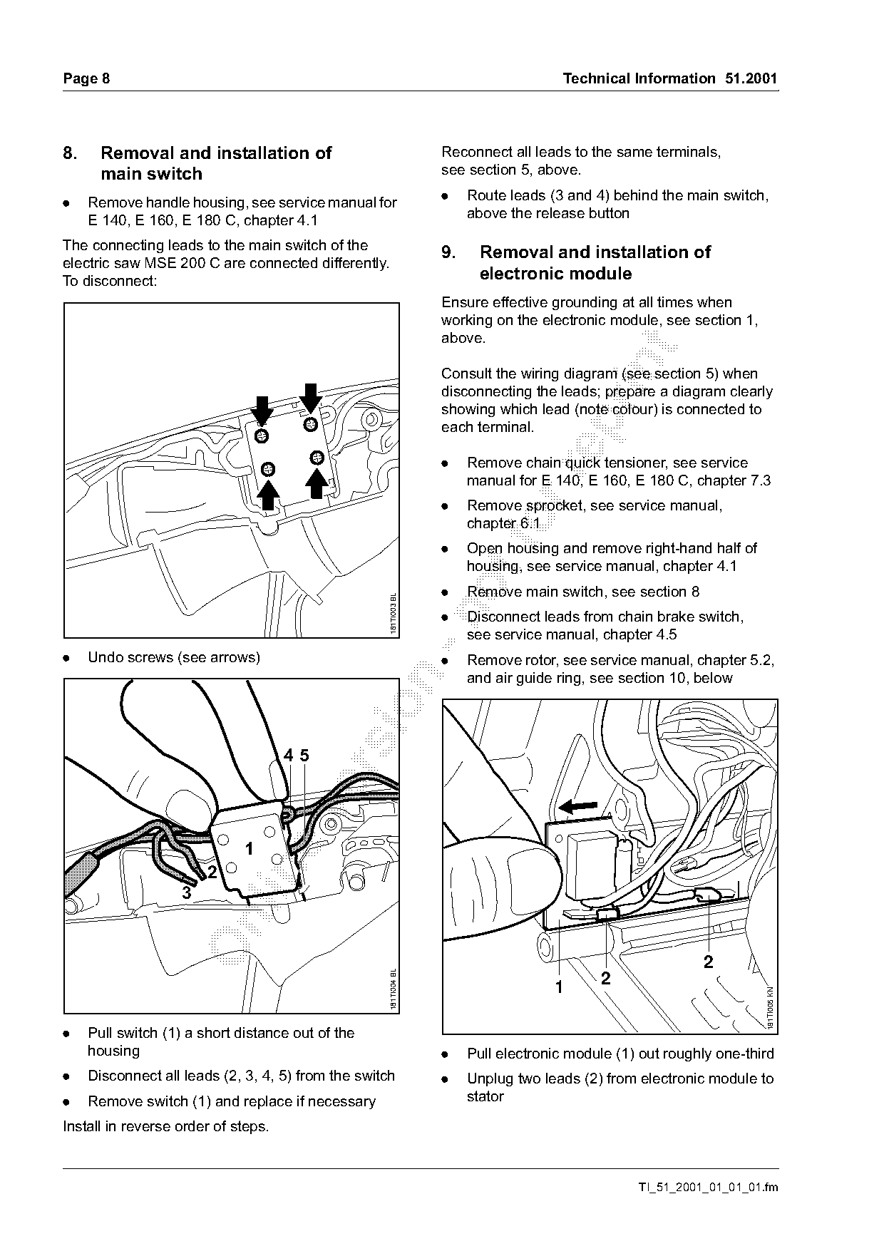
8.     Removal and installation of                                 Reconnect all leads to the same terminals,
       main switch                                                 see section 5, above.

.    Remove handle housing, see service manual for                 .    Route leads (3 and 4) behind the main switch,
     E 140, E 160, E 180 C, chapter 4.1                                 above the release button

The connecting leads to the main switch of the
                                                                   9.    Removal and installation of
electric saw MSE 200 C are connected differently.
To disconnect:                                                           electronic module
                                                                   Ensure effective grounding at all times when
                                                                   working on the electronic module, see section 1,
                                                                   above.

                                                                   Consult the wiring diagram (see section 5) when
                                                                   disconnecting the leads; prepare a diagram clearly
                                                                   showing which lead (note colour) is connected to

                                                                   each terminal.

                                                                   .    Remove chain quick tensioner, see service

                                                                        manual for E 140, E 160, E 180 C, chapter 7.3
                                                                   .    Remove sprocket, see service manual,

                                                                   .
                                                                        chapter 6.1
                                                                        Open housing and remove right-hand half of
                                                                        housing, see service manual, chapter 4.1
                                                                   .    Remove main switch, see section 8
                                                     181TI003 BL

                                                                   .    Disconnect leads from chain brake switch,
                                                                        see service manual, chapter 4.5
.    Undo screws (see arrows)                                      .    Remove rotor, see service manual, chapter 5.2,
                                                                        and air guide ring, see section 10, below


                        2
                    3

                                                                                                            2
                                                     181TI004 BL

                                                                                     1      2
                                                                                                                      181TI005 KN

.    Pull switch (1) a short distance out of the
     housing                                                       .    Pull electronic module (1) out roughly one-third
.    Disconnect all leads (2, 3, 4, 5) from the switch             .    Unplug two leads (2) from electronic module to
.    Remove switch (1) and replace if necessary                         stator

Install in reverse order of steps.

                                                                                                  TI_51_2001_01_01_01.fm
Page 9 of 12
Text of page 9 — search, copy, screen readers
Technical Information 51.2001                                                                                      Page 9

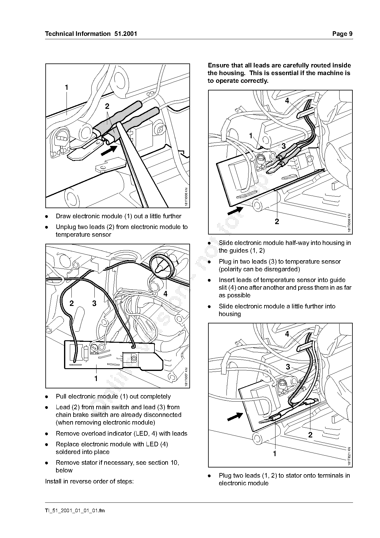
                                                                    Ensure that all leads are carefully routed inside
                                                                    the housing. This is essential if the machine is
                                                                    to operate correctly.
       1
                                                                                                 4
                         2

                                                                                   1
                                                                                                 3

                                                      181TI006 KN

.   Draw electronic module (1) out a little further

                                                                                                                         181TI008 KN
                                                                                             2
.   Unplug two leads (2) from electronic module to
    temperature sensor
                                                                    .   Slide electronic module half-way into housing in
                                                                        the guides (1, 2)
                                                                    .   Plug in two leads (3) to temperature sensor

                                                                        (polarity can be disregarded)
                                                                    .   Insert leads of temperature sensor into guide
                                                                        slit (4) one after another and press them in as far

                                            4                           as possible

           2      3                                                 .   Slide electronic module a little further into
                                                                        housing


                                                                                                     3
                                                      181TI007 KN


.   Pull electronic module (1) out completely

.   Lead (2) from main switch and lead (3) from
    chain brake switch are already disconnected
    (when removing electronic module)
.   Remove overload indicator (LED, 4) with leads                                                         2
.   Replace electronic module with LED (4)
                                                                                                                         181TI021 KN

    soldered into place                                                                     1
.   Remove stator if necessary, see section 10,
    below
                                                                    .   Plug two leads (1, 2) to stator onto terminals in
Install in reverse order of steps:                                      electronic module

TI_51_2001_01_01_01.fm
Page 10 of 12
Text of page 10 — search, copy, screen readers
Page 10                                                                                  Technical Information 51.2001

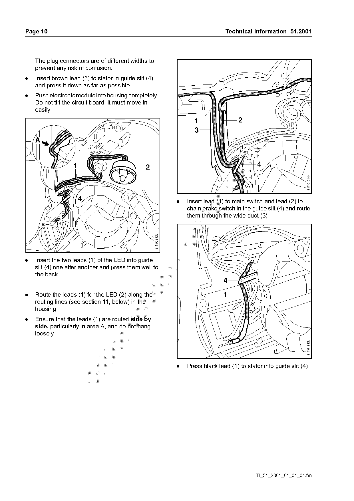
    The plug connectors are of different widths to
    prevent any risk of confusion.
.   Insert brown lead (3) to stator in guide slit (4)
    and press it down as far as possible
.   Push electronic module into housing completely.
    Do not tilt the circuit board: it must move in
    easily
                                                                             1                 2
                                                                             3
    A

                   1                             2                                                     4

                                                                                                                           181TI010 KN
                       4                                              .   Insert lead (1) to main switch and lead (2) to
                                                                          chain brake switch in the guide slit (4) and route
                                                                          them through the wide duct (3)
                                                        181TI009 KN

.   Insert the two leads (1) of the LED into guide
    slit (4) one after another and press them well to

    the back
                                                                                         4

.   Route the leads (1) for the LED (2) along the                                        1
    routing lines (see section 11, below) in the

    housing
.   Ensure that the leads (1) are routed side by

    side, particularly in area A, and do not hang
    loosely
                                                                                                                           181TI013 KN

                                                                      .   Press black lead (1) to stator into guide slit (4)

                                                                                                      TI_51_2001_01_01_01.fm
Page 11 of 12
Text of page 11 — search, copy, screen readers
Technical Information 51.2001                                                                                Page 11

                                                                   10. Removal and installation of stator
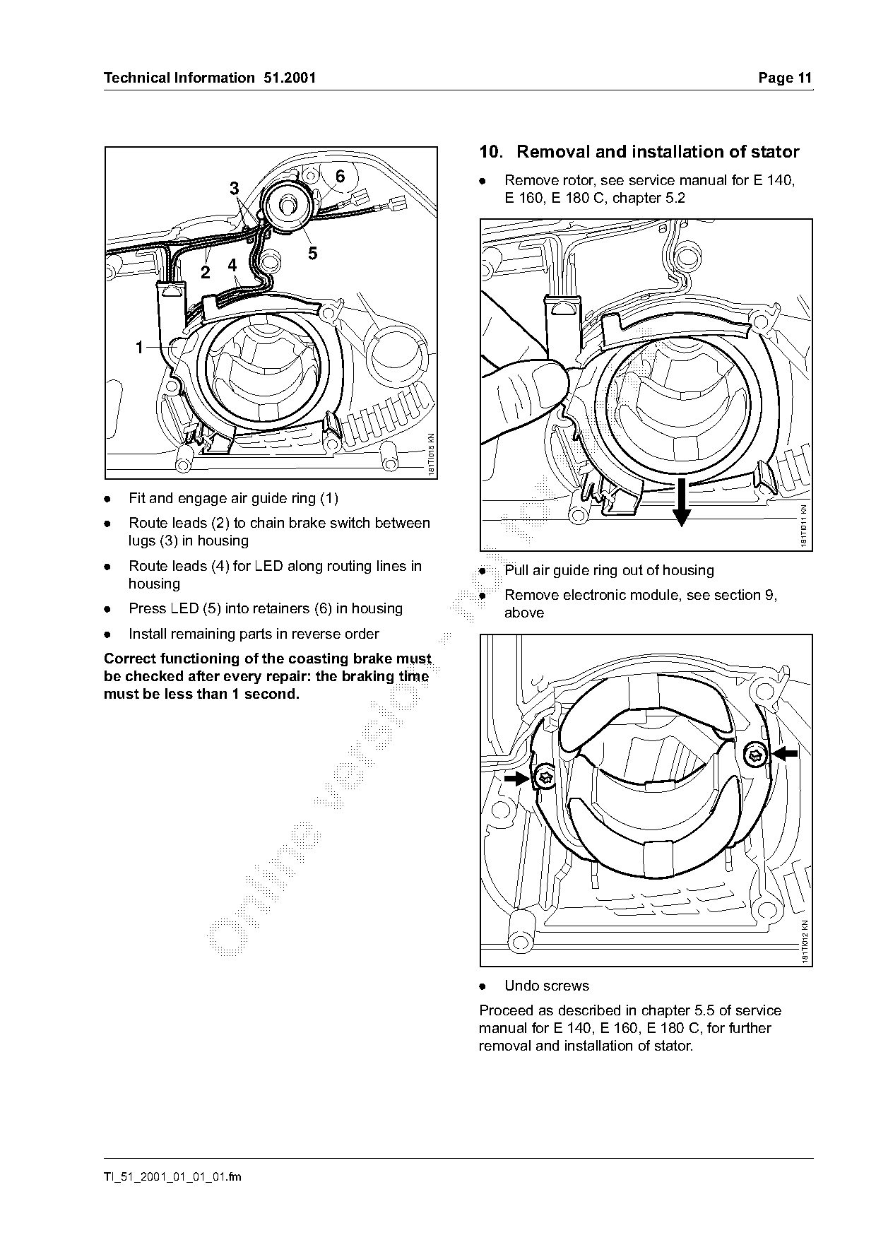
                                     6                             .   Remove rotor, see service manual for E 140,
                    3
                                                                       E 160, E 180 C, chapter 5.2

                                5
               2 4


                                                     181TI015 KN

.   Fit and engage air guide ring (1)

                                                                                                                     181TI011 KN
.   Route leads (2) to chain brake switch between
    lugs (3) in housing
.   Route leads (4) for LED along routing lines in
                                                                   .   Pull air guide ring out of housing
    housing
                                                                   .   Remove electronic module, see section 9,
.   Press LED (5) into retainers (6) in housing

                                                                       above
.   Install remaining parts in reverse order
Correct functioning of the coasting brake must

be checked after every repair: the braking time
must be less than 1 second.

                                                                                                                       181TI012 KN

                                                                   .   Undo screws
                                                                   Proceed as described in chapter 5.5 of service
                                                                   manual for E 140, E 160, E 180 C, for further
                                                                   removal and installation of stator.

TI_51_2001_01_01_01.fm
Page 12 of 12
Text of page 12 — search, copy, screen readers
Page 12                                                                           Technical Information 51.2001

11. Routing lines for wiring


                                                    181TI000 KN

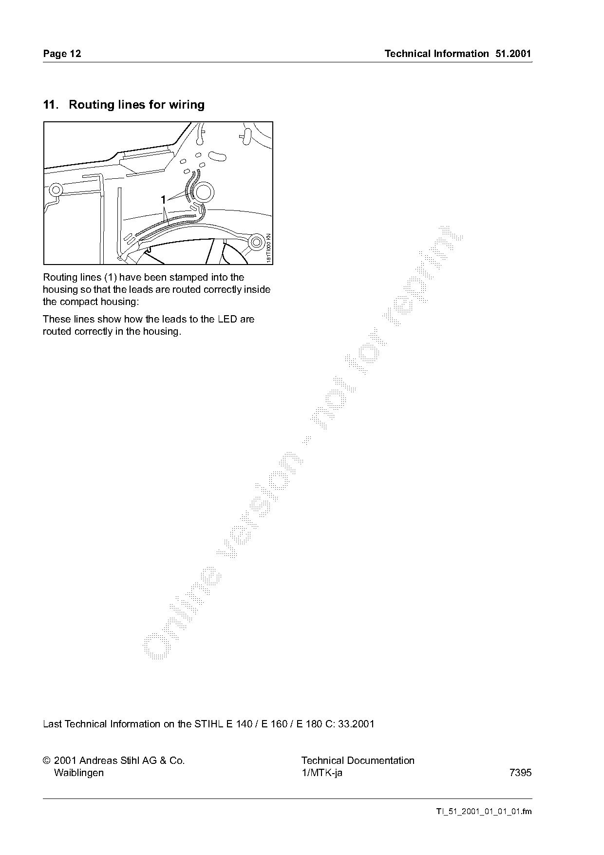
Routing lines (1) have been stamped into the

housing so that the leads are routed correctly inside
the compact housing:
These lines show how the leads to the LED are

routed correctly in the housing.

Last Technical Information on the STIHL E 140 / E 160 / E 180 C: 33.2001

© 2001 Andreas Stihl AG & Co.                                     Technical Documentation
  Waiblingen                                                      1/MTK-ja                                  7395

                                                                                            TI_51_2001_01_01_01.fm
Most of these PDFs embed fonts with a shifted character map, so the text above was recovered rather than copied — read it as a faithful but imperfect transcription, and treat the page image above each block as the authority where the two disagree — the figures exist only there, because they are vector drawings that text extraction cannot keep.