Technical Information · issue 2 of 2002
Ignition system
IssueTI 2/2002
Part changes (3)
| Was | Becomes | What the bulletin says |
|---|---|---|
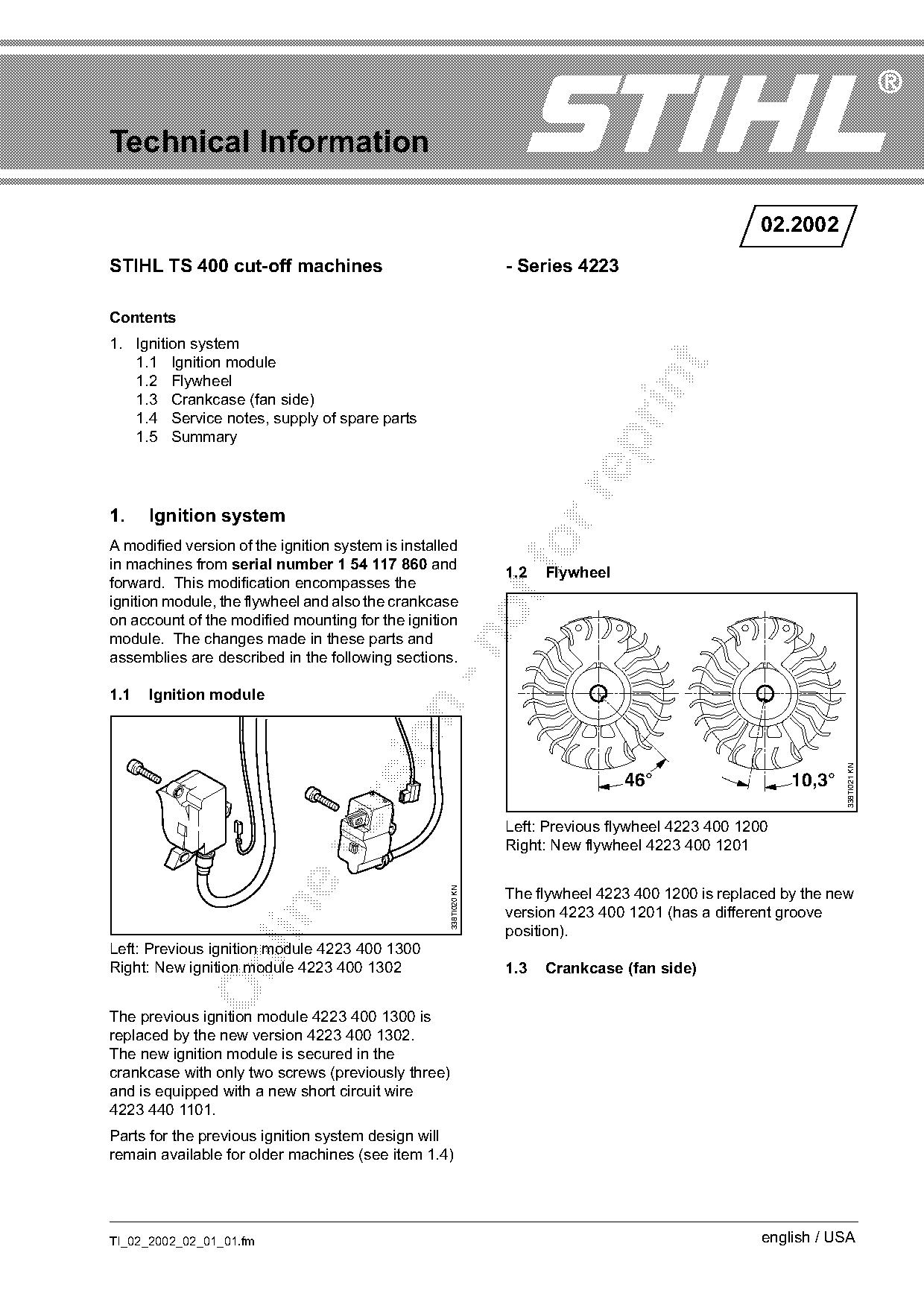
| 4223 400 1200 | 4223 400 1201 | The flywheel 4223 400 1200 is replaced by the new version 4223 400 1201 (has a different groove position). |
| 4223 400 1300 | 4223 400 1302 | The previous ignition module 4223 400 1300 is replaced by the new version 4223 400 1302. |
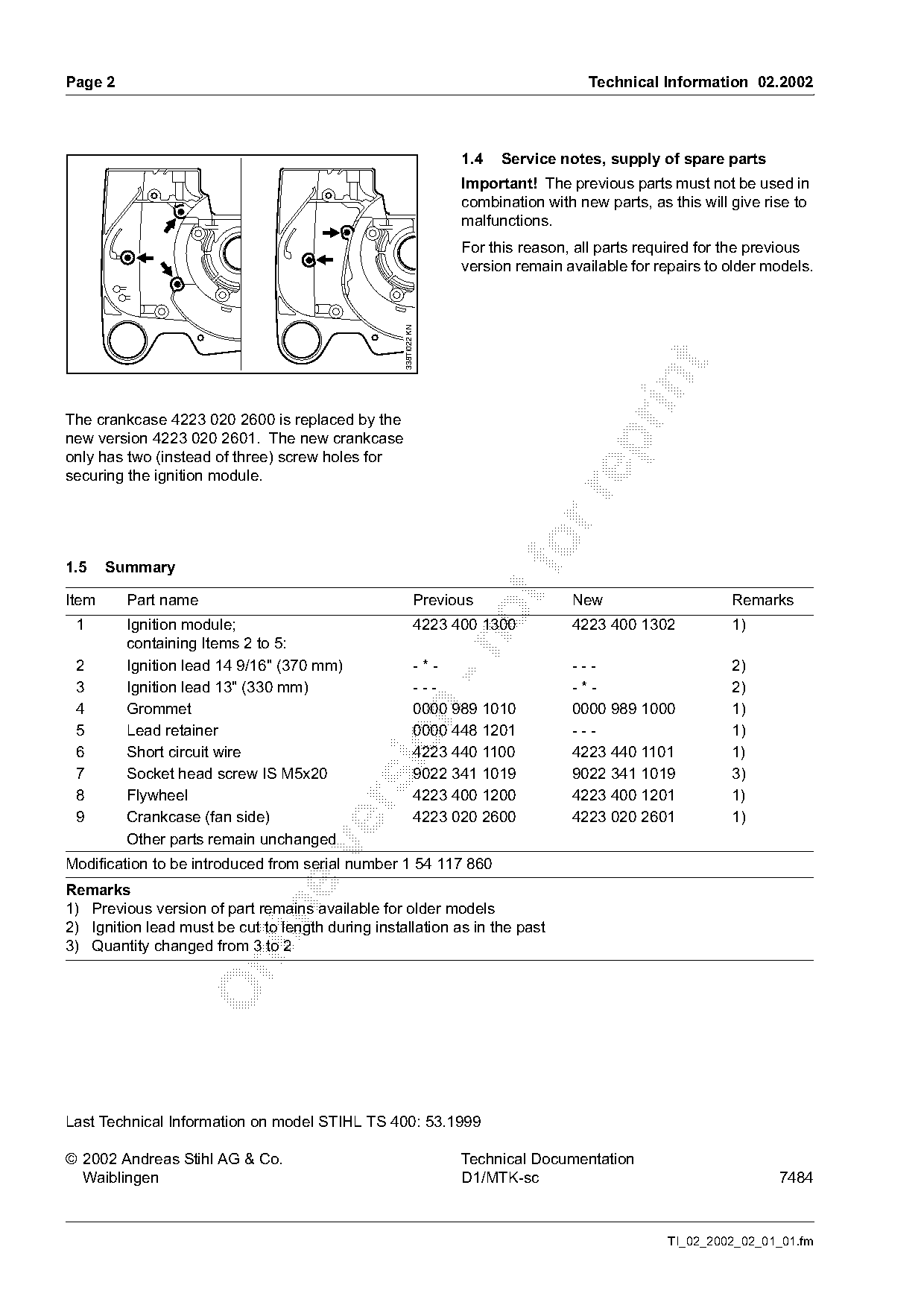
| 4223 020 2600 | 4223 020 2601 | The crankcase 4223 020 2600 is replaced by the new version 4223 020 2601. |
Full text
Page 1 of 2
Text of page 1 — search, copy, screen readers
Technical Information

                                                                                                     02.2002
STIHL TS 400 cut-off machines                                     - Series 4223

Contents
1. Ignition system
   1.1 Ignition module

   1.2 Flywheel

   1.3 Crankcase (fan side)
   1.4 Service notes, supply of spare parts
   1.5 Summary

1.    Ignition system
A modified version of the ignition system is installed
in machines from serial number 1 54 117 860 and
                                                                  1.2   Flywheel
forward. This modification encompasses the
ignition module, the flywheel and also the crankcase
on account of the modified mounting for the ignition
module. The changes made in these parts and

assemblies are described in the following sections.

1.1   Ignition module

                                                                                                                  338TI021 KN
                                                                                   46°                    10,3°

                                                                  Left: Previous flywheel 4223 400 1200
                                                                  Right: New flywheel 4223 400 1201

                                                    338TI020 KN

                                                                  The flywheel 4223 400 1200 is replaced by the new

                                                                  version 4223 400 1201 (has a different groove
                                                                  position).
Left: Previous ignition module 4223 400 1300

Right: New ignition module 4223 400 1302                          1.3   Crankcase (fan side)

The previous ignition module 4223 400 1300 is
replaced by the new version 4223 400 1302.
The new ignition module is secured in the
crankcase with only two screws (previously three)
and is equipped with a new short circuit wire
4223 440 1101.
Parts for the previous ignition system design will
remain available for older machines (see item 1.4)

TI_02_2002_02_01_01.fm                                                                                english / USA
Page 2 of 2
Text of page 2 — search, copy, screen readers
Page 2                                                                                Technical Information 02.2002

                                                                   1.4   Service notes, supply of spare parts
                                                                   Important! The previous parts must not be used in
                                                                   combination with new parts, as this will give rise to
                                                                   malfunctions.
                                                                   For this reason, all parts required for the previous
                                                                   version remain available for repairs to older models.

                                                   338TI022 KN

The crankcase 4223 020 2600 is replaced by the
new version 4223 020 2601. The new crankcase

only has two (instead of three) screw holes for
securing the ignition module.

1.5    Summary
Item     Part name                                           Previous              New                      Remarks
 1       Ignition module;                                    4223 400 1300         4223 400 1302            1)

         containing Items 2 to 5:
 2       Ignition lead 14 9/16" (370 mm)                     -*-                   ---                      2)
 3       Ignition lead 13" (330 mm)                          ---                   -*-                      2)
 4       Grommet                                             0000 989 1010         0000 989 1000            1)

 5       Lead retainer                                       0000 448 1201         ---                      1)

 6       Short circuit wire                                  4223 440 1100         4223 440 1101            1)
 7       Socket head screw IS M5x20                          9022 341 1019         9022 341 1019            3)
 8       Flywheel                                            4223 400 1200         4223 400 1201            1)

 9       Crankcase (fan side)                                4223 020 2600         4223 020 2601            1)
         Other parts remain unchanged

Modification to be introduced from serial number 1 54 117 860
Remarks
1) Previous version of part remains available for older models

2) Ignition lead must be cut to length during installation as in the past
3) Quantity changed from 3 to 2

Last Technical Information on model STIHL TS 400: 53.1999

© 2002 Andreas Stihl AG & Co.                                      Technical Documentation
  Waiblingen                                                       D1/MTK-sc                                       7484

                                                                                                  TI_02_2002_02_01_01.fm
Most of these PDFs embed fonts with a shifted character map, so the text above was recovered rather than copied — read it as a faithful but imperfect transcription, and treat the page image above each block as the authority where the two disagree — the figures exist only there, because they are vector drawings that text extraction cannot keep.