Technical Information · issue 5 of 2002
New Sales Designations for 021, 023 and 025; Uprat
Model MS 210, MS 250 Chainsaws – Series 1123
IssueTI 5/2002
Engine family 1123
Part changes (2)
| Was | Becomes | What the bulletin says |
|---|---|---|
| 1117 350 5800 | 0000 350 5802 | The previous tank vent 1117 350 5800 has been replaced by the new version 0000 350 5802. |
| 1123 640 2900 | 1123 640 2901 | Fan Housing (round nameplate) The connector 1123 640 2900 has been replaced by The fan housings of the renamed models have been connector 1123 640 2901. |
Full text
Page 1 of 10
Text of page 1 — search, copy, screen readers
Technical Information

                                                                                             05.2002
Model MS 210, MS 250 Chainsaws – Series 1123

Contents
1. New Sales Designations for
    021 and 025

2. Uprated Engine

3. Carburetor
4. Tank Caps
5. Tank Vent

6. Engine Housing - Connector - Oil Pump
7. Fan Housing (round nameplate)
8. Carburetor Box Cover / Handle Housing

9. Muffler
10. Crankshaft (MS 210)
11. Spare Parts
12. Summary

1.    New Sales Designations for

      021 and 025
Models 021 and 025 have been renamed
STIHL MS 210 and STIHL MS 250 to bring them

into line with the new naming structure (see
TI 25.2000).

2.    Uprated Engine

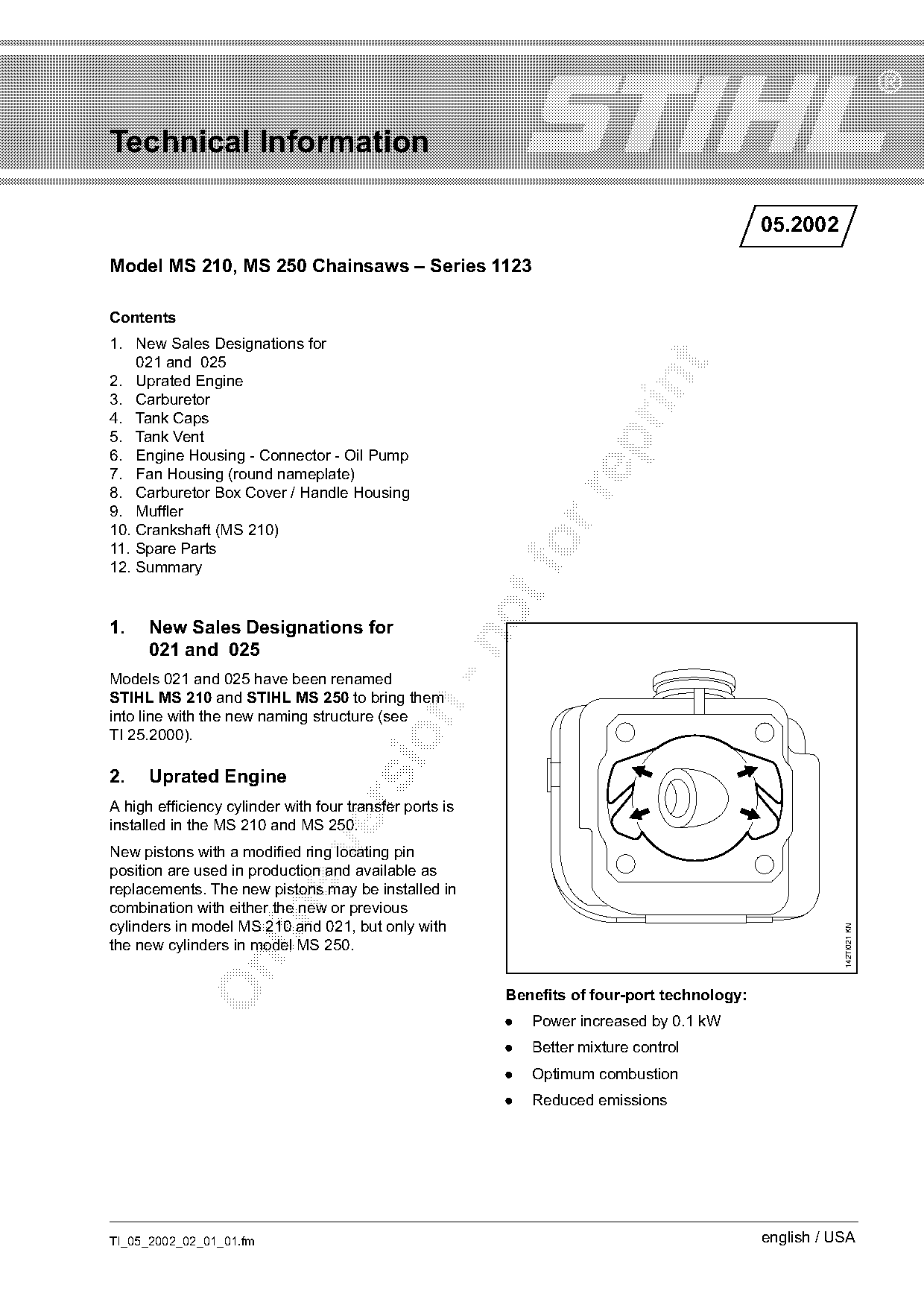
A high efficiency cylinder with four transfer ports is
installed in the MS 210 and MS 250.

New pistons with a modified ring locating pin
position are used in production and available as
replacements. The new pistons may be installed in
combination with either the new or previous

cylinders in model MS 210 and 021, but only with
                                                                                                        142TI021 KN

the new cylinders in model MS 250.

                                                         Benefits of four-port technology:
                                                         .   Power increased by 0.1 kW
                                                         .   Better mixture control
                                                         .   Optimum combustion
                                                         .   Reduced emissions

TI_05_2002_02_01_01.fm                                                                       english / USA
Page 2 of 10
Text of page 2 — search, copy, screen readers
Page 2                                                                                    Technical Information 05.2002

3.     Carburetor
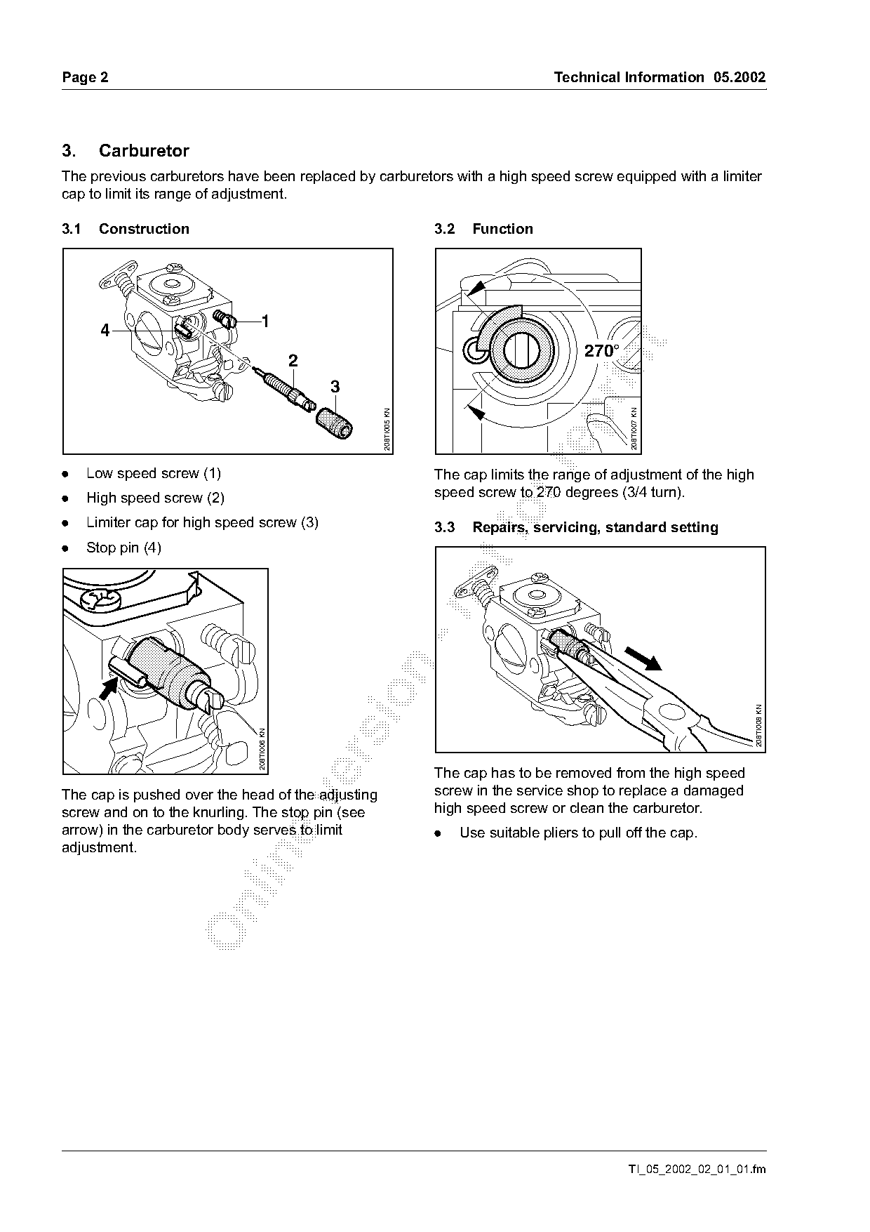
The previous carburetors have been replaced by carburetors with a high speed screw equipped with a limiter
cap to limit its range of adjustment.

3.1    Construction                                                  3.2     Function

                                   1
        4

                                                                                                270°

                                              2
                                                  3

                                                                                                       208TI007 KN
                                                       208TI005 KN

.     Low speed screw (1)                                            The cap limits the range of adjustment of the high
.     High speed screw (2)                                           speed screw to 270 degrees (3/4 turn).

.     Limiter cap for high speed screw (3)                           3.3
                                                                             Repairs, servicing, standard setting
.     Stop pin (4)

                                                                                                                           208TI008 KN
                                208TI006 KN

                                                                     The cap has to be removed from the high speed
The cap is pushed over the head of the adjusting                     screw in the service shop to replace a damaged

screw and on to the knurling. The stop pin (see                      high speed screw or clean the carburetor.
arrow) in the carburetor body serves to limit                        .     Use suitable pliers to pull off the cap.
adjustment.

                                                                                                       TI_05_2002_02_01_01.fm
Page 3 of 10
Text of page 3 — search, copy, screen readers
Technical Information 05.2002                                                                          Page 3

! Caps that have been removed once must not             3.3.4 Adjusting idle speed
be re-used. Fit new caps.

3.3.1 Adjustment after repairs / servicing
.   Check the air filter and clean or replace as                                 L
    necessary.                                                                  1/4

.   Check spark arresting screen and clean or
    replace as necessary.
.   Check fuel filter and clean or replace as
    necessary.

                                                                                         208TI011 KN
                                                                    LA

.   Check chain tension.

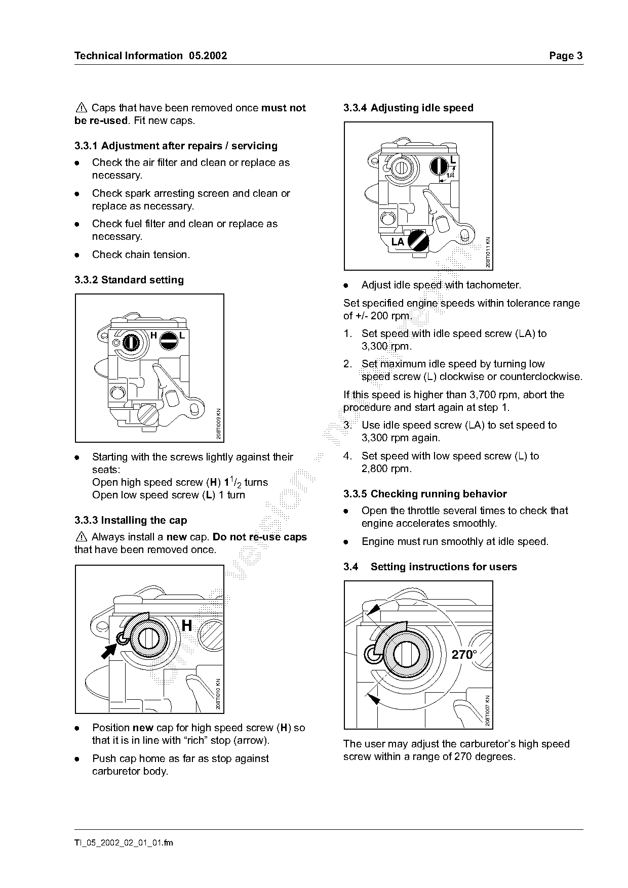
3.3.2 Standard setting
                                                        .     Adjust idle speed with tachometer.

                                                        Set specified engine speeds within tolerance range
                                                        of +/- 200 rpm.
                                                        1. Set speed with idle speed screw (LA) to

                 H       L
                                                           3,300 rpm.
                                                        2. Set maximum idle speed by turning low
                                                           speed screw (L) clockwise or counterclockwise.
                                                        If this speed is higher than 3,700 rpm, abort the
                                                        procedure and start again at step 1.
                                 208TI009 KN

                                                        3. Use idle speed screw (LA) to set speed to

                                                           3,300 rpm again.
.   Starting with the screws lightly against their      4. Set speed with low speed screw (L) to
    seats:                                                 2,800 rpm.
    Open high speed screw (H) 11/2 turns

    Open low speed screw (L) 1 turn                     3.3.5 Checking running behavior

                                                        .     Open the throttle several times to check that
3.3.3 Installing the cap                                      engine accelerates smoothly.
! Always install a new cap. Do not re-use caps          .     Engine must run smoothly at idle speed.

that have been removed once.
                                                        3.4    Setting instructions for users


                                                                                  270°
                                208TI010 KN

                                                                                         208TI007 KN

.   Position new cap for high speed screw (H) so
    that it is in line with “rich” stop (arrow).        The user may adjust the carburetor’s high speed
.   Push cap home as far as stop against                screw within a range of 270 degrees.
    carburetor body.

TI_05_2002_02_01_01.fm
Page 4 of 10
Text of page 4 — search, copy, screen readers
Page 4                                                                                Technical Information 05.2002

This enables the mixture to be made leaner for                    4.2    Operation
operation at high altitudes.
                                                                  4.2.1 Opening
The procedure for setting the new carburetors is as
described in the owner’s manual (see chapter
"Adjusting the Carburetor").

Note on spare parts:
Carburetor parts kit 1123 007 1060 is available
(special accessory) for the new carburetors with
limiter cap.

                                                                                                                        176TI001 KN
4.     Tank Caps

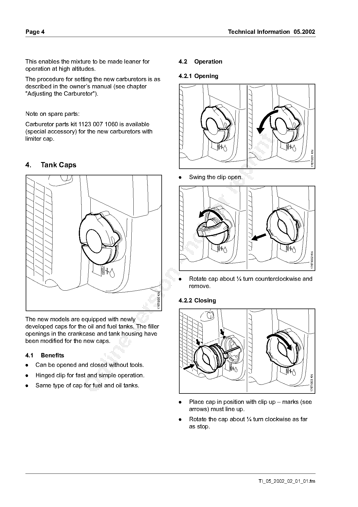
                                                                  .     Swing the clip open.

                                                                                                                       176TI002 KN

                                                                  .     Rotate cap about ¼ turn counterclockwise and
                                                                        remove.
                                                 sio176TI000 KN

                                                                  4.2.2 Closing

The new models are equipped with newly
developed caps for the oil and fuel tanks. The filler

openings in the crankcase and tank housing have
been modified for the new caps.

4.1    Benefits
.     Can be opened and closed without tools.

.     Hinged clip for fast and simple operation.
                                                                                                                       176TI003 KN

.     Same type of cap for fuel and oil tanks.

                                                                  .     Place cap in position with clip up – marks (see
                                                                        arrows) must line up.
                                                                  .     Rotate the cap about ¼ turn clockwise as far
                                                                        as stop.

                                                                                                  TI_05_2002_02_01_01.fm
Page 5 of 10
Text of page 5 — search, copy, screen readers
Technical Information 05.2002                                                                                  Page 5

                                                   176TI004 KN

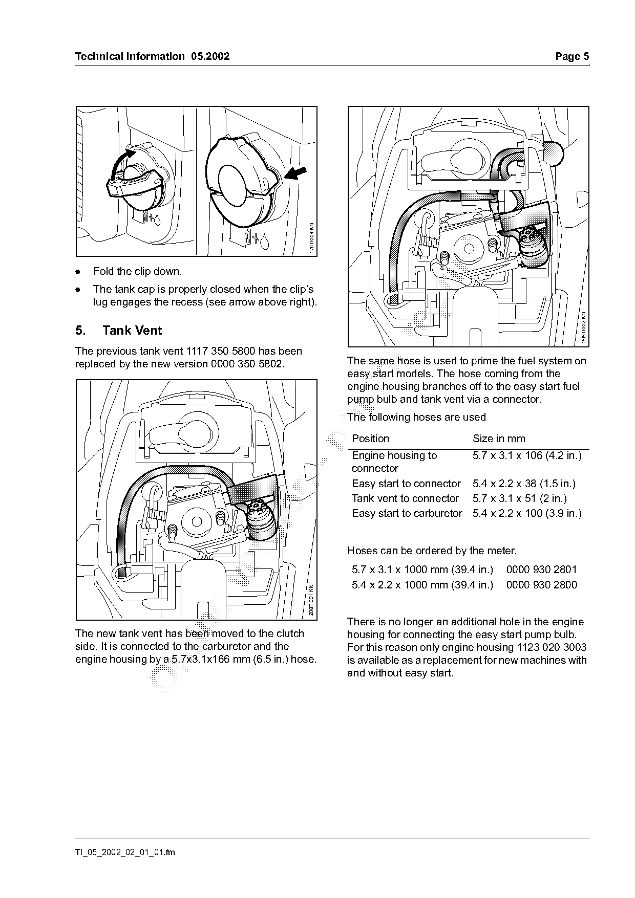
.    Fold the clip down.
.    The tank cap is properly closed when the clip’s
     lug engages the recess (see arrow above right).

                                                                                                                     208TI002 KN
5.    Tank Vent

The previous tank vent 1117 350 5800 has been
replaced by the new version 0000 350 5802.                       The same hose is used to prime the fuel system on
                                                                 easy start models. The hose coming from the
                                                                 engine housing branches off to the easy start fuel
                                                                 pump bulb and tank vent via a connector.
                                                                 The following hoses are used

                                                                  Position                   Size in mm

                                                                  Engine housing to          5.7 x 3.1 x 106 (4.2 in.)
                                                                  connector
                                                                  Easy start to connector    5.4 x 2.2 x 38 (1.5 in.)

                                                                  Tank vent to connector     5.7 x 3.1 x 51 (2 in.)

                                                                  Easy start to carburetor   5.4 x 2.2 x 100 (3.9 in.)

                                                                 Hoses can be ordered by the meter.

                                                                  5.7 x 3.1 x 1000 mm (39.4 in.)    0000 930 2801

                                                                  5.4 x 2.2 x 1000 mm (39.4 in.)    0000 930 2800
                                                  208TI001 KN

                                                                 There is no longer an additional hole in the engine

The new tank vent has been moved to the clutch                   housing for connecting the easy start pump bulb.
side. It is connected to the carburetor and the                  For this reason only engine housing 1123 020 3003
engine housing by a 5.7x3.1x166 mm (6.5 in.) hose.               is available as a replacement for new machines with

                                                                 and without easy start.

TI_05_2002_02_01_01.fm
Page 6 of 10
Text of page 6 — search, copy, screen readers
Page 6                                                                                  Technical Information 05.2002

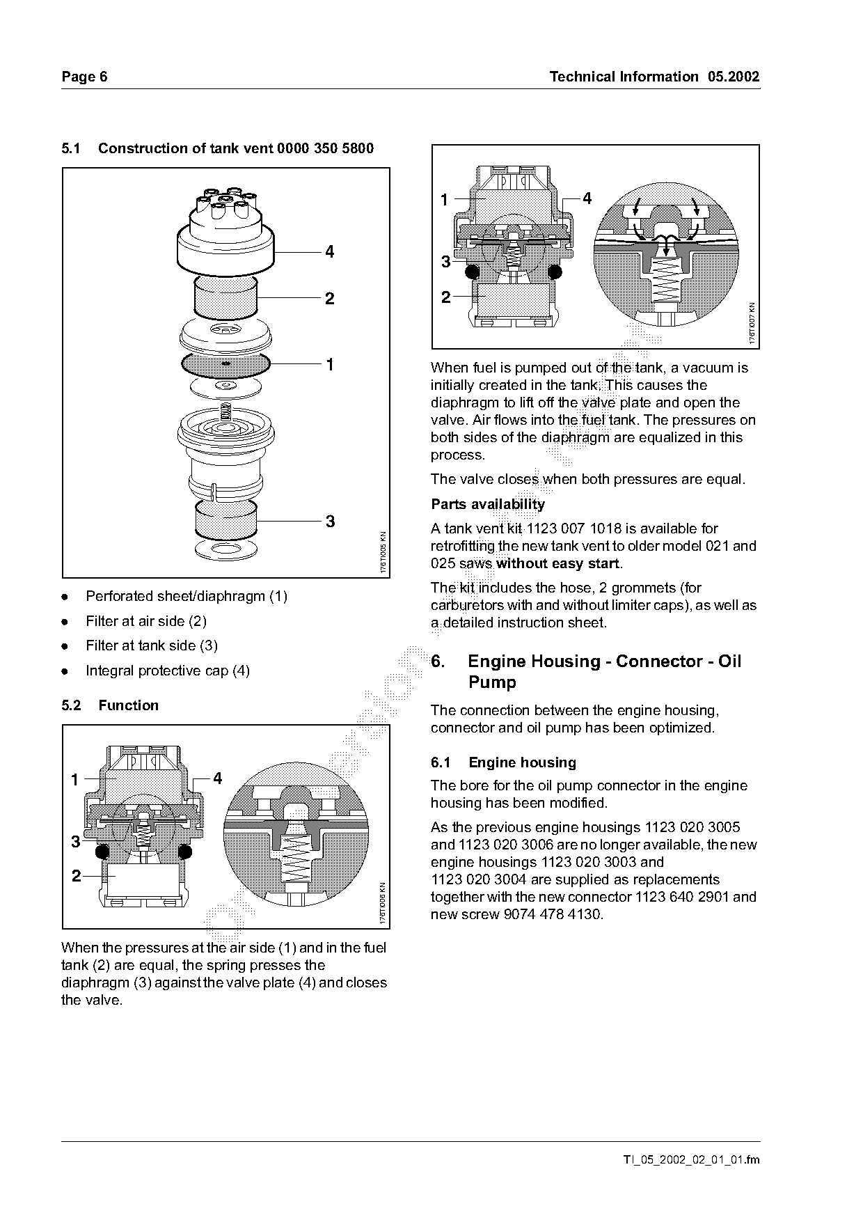
5.1       Construction of tank vent 0000 350 5800

                                                                    1                       4

                                           4
                                                                    3

                                           2                        2

                                                                                                                       176TI007 KN
                                           1                       When fuel is pumped out of the tank, a vacuum is
                                                                   initially created in the tank. This causes the
                                                                   diaphragm to lift off the valve plate and open the

                                                                   valve. Air flows into the fuel tank. The pressures on
                                                                   both sides of the diaphragm are equalized in this
                                                                   process.

                                                                   The valve closes when both pressures are equal.
                                                                   Parts availability
                                           3                               fo
                                                                   A tank vent kit 1123 007 1018 is available for
                                                     176TI005 KN

                                                                   retrofitting the new tank vent to older model 021 and
                                                                   025 saws without easy start.
                                                                   The kit includes the hose, 2 grommets (for
.       Perforated sheet/diaphragm (1)

                                                                   carburetors with and without limiter caps), as well as
.       Filter at air side (2)                                     a detailed instruction sheet.
.       Filter at tank side (3)
                                                                   6.    Engine Housing - Connector - Oil

.       Integral protective cap (4)
                                                                         Pump

5.2       Function                                                 The connection between the engine housing,
                                                                   connector and oil pump has been optimized.

                                                                   6.1   Engine housing
    1                            4                                 The bore for the oil pump connector in the engine

                                                                   housing has been modified.
                                                                   As the previous engine housings 1123 020 3005
    3                                                              and 1123 020 3006 are no longer available, the new

                                                                   engine housings 1123 020 3003 and
    2                                                              1123 020 3004 are supplied as replacements
                                                    176TI006 KN

                                                                   together with the new connector 1123 640 2901 and

                                                                   new screw 9074 478 4130.

When the pressures at the air side (1) and in the fuel
tank (2) are equal, the spring presses the
diaphragm (3) against the valve plate (4) and closes
the valve.

                                                                                                  TI_05_2002_02_01_01.fm
Page 7 of 10
Text of page 7 — search, copy, screen readers
Technical Information 05.2002                                                                                   Page 7

6.2   Connector                                                  7.    Fan Housing (round nameplate)
The connector 1123 640 2900 has been replaced by                 The fan housings of the renamed models have been
connector 1123 640 2901. The new version has a                   modified to accommodate a round nameplate. The
larger through-hole to take the new spline socket                slotted area has been enlarged for more efficient
head screw.                                                      cooling of the uprated engine.
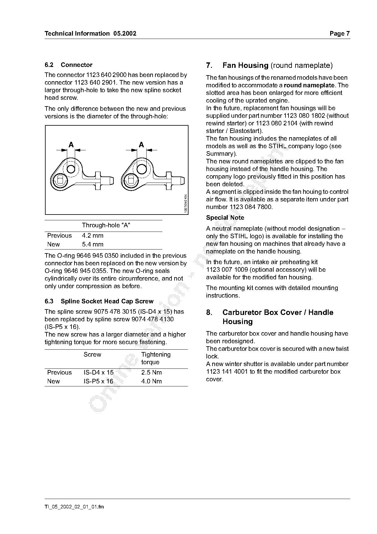
The only difference between the new and previous                 In the future, replacement fan housings will be
versions is the diameter of the through-hole:                    supplied under part number 1123 080 1802 (without
                                                                 rewind starter) or 1123 080 2104 (with rewind
                                                                 starter / Elastostart).
                                                                 The fan housing includes the nameplates of all
        A                         A                              models as well as the STIHL company logo (see

                                                                 Summary).

                                                                 The new round nameplates are clipped to the fan
                                                                 housing instead of the handle housing. The
                                                                 company logo previously fitted in this position has

                                                                 been deleted.
                                                                 A segment is clipped inside the fan houing to control
                                                   135TI040 KN

                                                                 air flow. It is available as a separate item under part

                                                                 number 1123 084 7800.
                                                                 Special Note

Previous
             Through-hole "A"
             4.2 mm
                                                                 A neutral nameplate (without model designation –
                                                                 only the STIHL logo) is available for installing the
New          5.4 mm                                              new fan housing on machines that already have a
                                                                 nameplate on the handle housing.
The O-ring 9646 945 0350 included in the previous
                                                                 In the future, an intake air preheating kit

connector has been replaced on the new version by
O-ring 9646 945 0355. The new O-ring seals                       1123 007 1009 (optional accessory) will be
cylindrically over its entire circumference, and not             available for the modified fan housing.
only under compression as before.                                The mounting kit comes with detailed mounting

                                                                 instructions.
6.3   Spline Socket Head Cap Screw

The spline screw 9075 478 3015 (IS-D4 x 15) has                  8.    Carburetor Box Cover / Handle
been replaced by spline screw 9074 478 4130                            Housing
(IS-P5 x 16).

The new screw has a larger diameter and a higher                 The carburetor box cover and handle housing have
tightening torque for more secure fastening.                     been redesigned.

                                                                 The carburetor box cover is secured with a new twist
              Screw                Tightening                    lock.
                                   torque                        A new winter shutter is available under part number
                                                                 1123 141 4001 to fit the modified carburetor box

Previous      IS-D4 x 15           2.5 Nm
New           IS-P5 x 16           4.0 Nm                        cover.

TI_05_2002_02_01_01.fm
Page 8 of 10
Text of page 8 — search, copy, screen readers
Page 8                                                             Technical Information 05.2002

9.    Muffler
The new muffler 1123 140 0606 has upper and
lower casings that are flanged and the exhaust
outlet is louvered.
Muffler 1123 140 0605 remains available as a
replacement for models 021 and 025.

10. Crankshaft (MS 210)

In the future, a new crankshaft 1123 030 0411 will

be installed on the production line and be available
as a replacement for the MS 210. This new version
features an optimized big-end bearing.

11. Spare Parts

Separate illustrated parts lists are available for the
new chainsaws.
The parts lists for these chainsaws are included in
the 03.2002 issues of the microfiche and CD-ROM.

                                                                             TI_05_2002_02_01_01.fm
Page 9 of 10
Text of page 9 — search, copy, screen readers
Technical Information 05.2002                                                                    Page 9

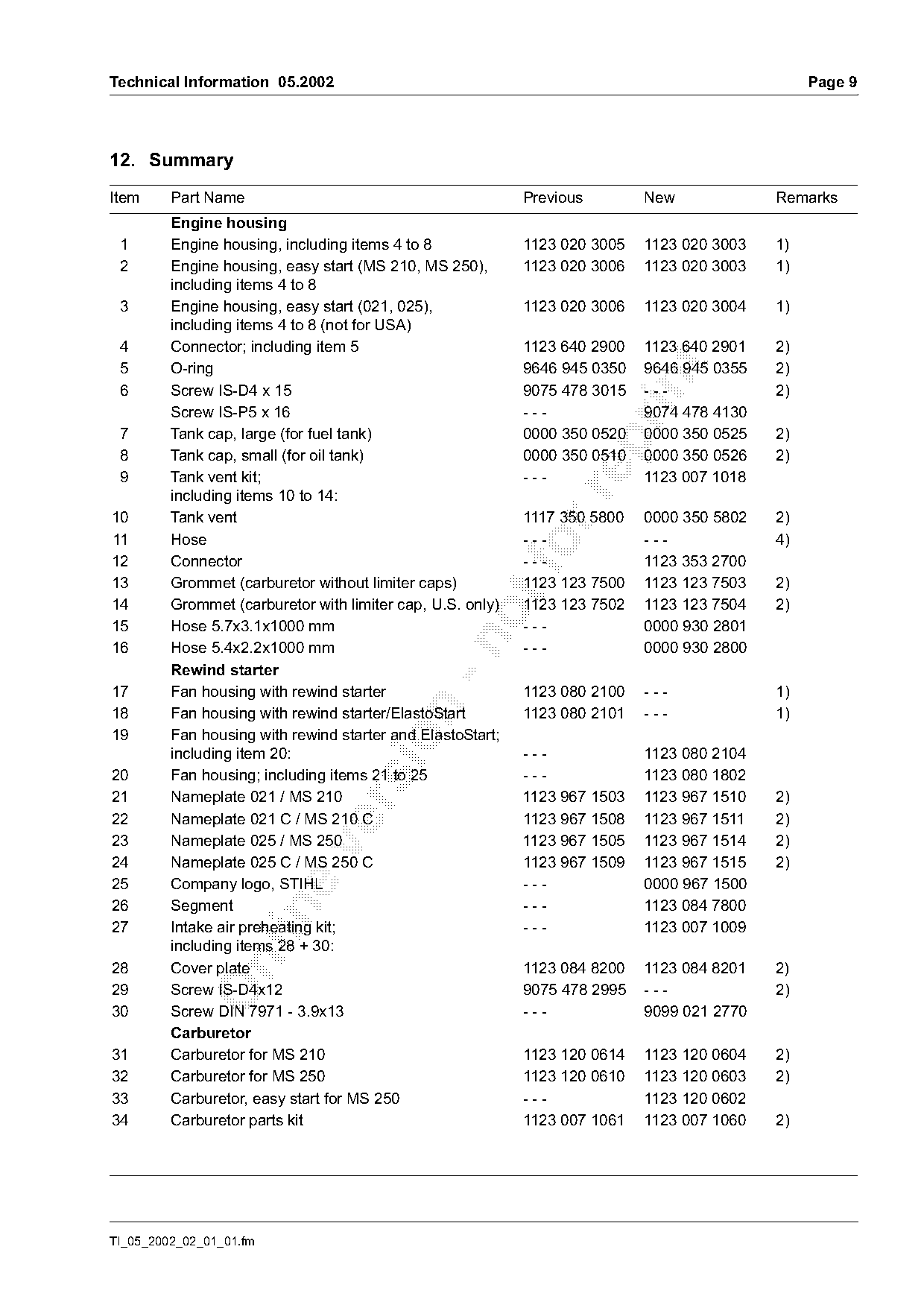
12. Summary
Item     Part Name                                          Previous        New             Remarks
         Engine housing
 1       Engine housing, including items 4 to 8             1123 020 3005   1123 020 3003   1)
 2       Engine housing, easy start (MS 210, MS 250),       1123 020 3006   1123 020 3003   1)
         including items 4 to 8
 3       Engine housing, easy start (021, 025),             1123 020 3006   1123 020 3004   1)
         including items 4 to 8 (not for USA)
 4       Connector; including item 5                        1123 640 2900   1123 640 2901   2)

 5       O-ring                                             9646 945 0350   9646 945 0355   2)

 6       Screw IS-D4 x 15                                   9075 478 3015   ---             2)
         Screw IS-P5 x 16                                   ---             9074 478 4130
 7       Tank cap, large (for fuel tank)                    0000 350 0520   0000 350 0525   2)

 8       Tank cap, small (for oil tank)                     0000 350 0510   0000 350 0526   2)
 9       Tank vent kit;                                     ---             1123 007 1018

         including items 10 to 14:
10       Tank vent                                          1117 350 5800   0000 350 5802   2)
11       Hose                                               ---             ---             4)
12       Connector
                                                            ---             1123 353 2700
13       Grommet (carburetor without limiter caps)          1123 123 7500   1123 123 7503   2)
14       Grommet (carburetor with limiter cap, U.S. only)   1123 123 7502   1123 123 7504   2)
15       Hose 5.7x3.1x1000 mm                               ---             0000 930 2801

16       Hose 5.4x2.2x1000 mm                               ---             0000 930 2800
         Rewind starter
17       Fan housing with rewind starter                    1123 080 2100   ---             1)

18       Fan housing with rewind starter/ElastoStart        1123 080 2101   ---             1)
19       Fan housing with rewind starter and ElastoStart;

         including item 20:                                 ---             1123 080 2104
20       Fan housing; including items 21 to 25              ---             1123 080 1802
21       Nameplate 021 / MS 210                             1123 967 1503   1123 967 1510   2)

22       Nameplate 021 C / MS 210 C                         1123 967 1508   1123 967 1511   2)
23       Nameplate 025 / MS 250                             1123 967 1505   1123 967 1514   2)

24       Nameplate 025 C / MS 250 C                         1123 967 1509   1123 967 1515   2)
25       Company logo, STIHL                                ---             0000 967 1500
26       Segment                                            ---             1123 084 7800

27       Intake air preheating kit;                         ---             1123 007 1009
         including items 28 + 30:

28       Cover plate                                        1123 084 8200   1123 084 8201   2)
29       Screw IS-D4x12                                     9075 478 2995   ---             2)
30       Screw DIN 7971 - 3.9x13                            ---             9099 021 2770
         Carburetor
31       Carburetor for MS 210                              1123 120 0614   1123 120 0604   2)
32       Carburetor for MS 250                              1123 120 0610   1123 120 0603   2)
33       Carburetor, easy start for MS 250                  ---             1123 120 0602
34       Carburetor parts kit                               1123 007 1061   1123 007 1060   2)

TI_05_2002_02_01_01.fm
Page 10 of 10
Text of page 10 — search, copy, screen readers
Page 10                                                                     Technical Information 05.2002

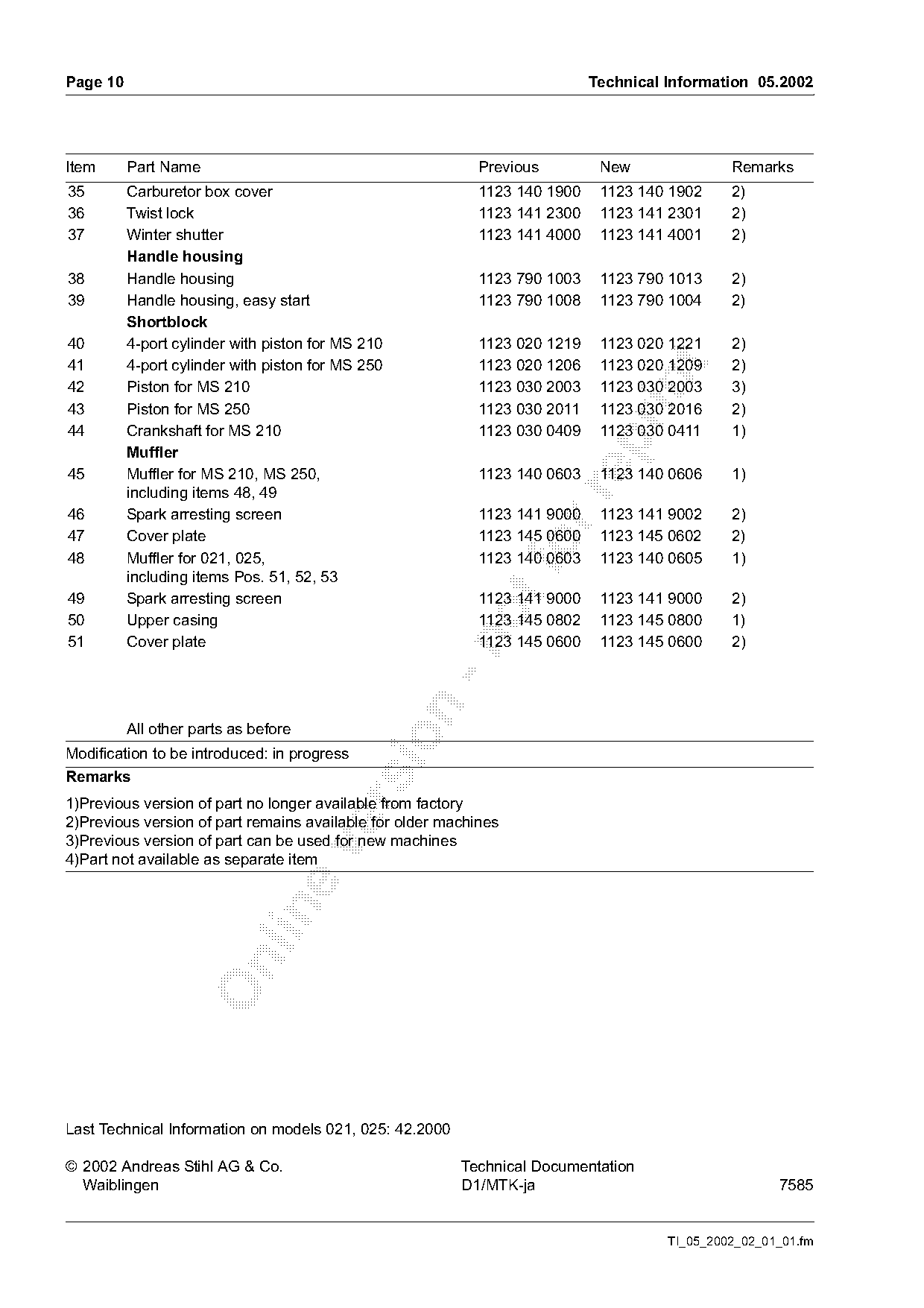
Item      Part Name                                         Previous         New               Remarks
35        Carburetor box cover                              1123 140 1900    1123 140 1902     2)
36        Twist lock                                        1123 141 2300    1123 141 2301     2)
37        Winter shutter                                    1123 141 4000    1123 141 4001     2)
          Handle housing
38        Handle housing                                    1123 790 1003    1123 790 1013     2)
39        Handle housing, easy start                        1123 790 1008    1123 790 1004     2)
          Shortblock
40        4-port cylinder with piston for MS 210            1123 020 1219    1123 020 1221     2)
41        4-port cylinder with piston for MS 250            1123 020 1206    1123 020 1209     2)

42        Piston for MS 210                                 1123 030 2003    1123 030 2003     3)
43        Piston for MS 250                                 1123 030 2011    1123 030 2016     2)
44        Crankshaft for MS 210                             1123 030 0409    1123 030 0411     1)

          Muffler
45        Muffler for MS 210, MS 250,                       1123 140 0603    1123 140 0606     1)
          including items 48, 49

46        Spark arresting screen                            1123 141 9000    1123 141 9002     2)
47        Cover plate                                       1123 145 0600    1123 145 0602     2)
48        Muffler for 021, 025,
          including items Pos. 51, 52, 53
                                                            1123 140 0603    1123 140 0605     1)

49        Spark arresting screen                            1123 141 9000    1123 141 9000     2)
50        Upper casing                                      1123 145 0802    1123 145 0800     1)
51        Cover plate                                       1123 145 0600    1123 145 0600     2)

          All other parts as before

Modification to be introduced: in progress
Remarks
1)Previous version of part no longer available from factory

2)Previous version of part remains available for older machines
3)Previous version of part can be used for new machines

4)Part not available as separate item

Last Technical Information on models 021, 025: 42.2000

© 2002 Andreas Stihl AG & Co.                            Technical Documentation
  Waiblingen                                             D1/MTK-ja                                    7585

                                                                                      TI_05_2002_02_01_01.fm
Most of these PDFs embed fonts with a shifted character map, so the text above was recovered rather than copied — read it as a faithful but imperfect transcription, and treat the page image above each block as the authority where the two disagree — the figures exist only there, because they are vector drawings that text extraction cannot keep.