Technical Information · issue 6 of 2002
New edger STIHL FC 110
IssueTI 6/2002
Full text
Page 1 of 12
Text of page 1 — search, copy, screen readers
Technical Information

                                                                   06.2002
New edger STIHL FC 110 – Series 4180

Contents
1.   Technical description
2.   Specifications

3.   Cutting blade

4.   Accessories
5.   Service accessories
6.   Service notes

7.   Spare parts

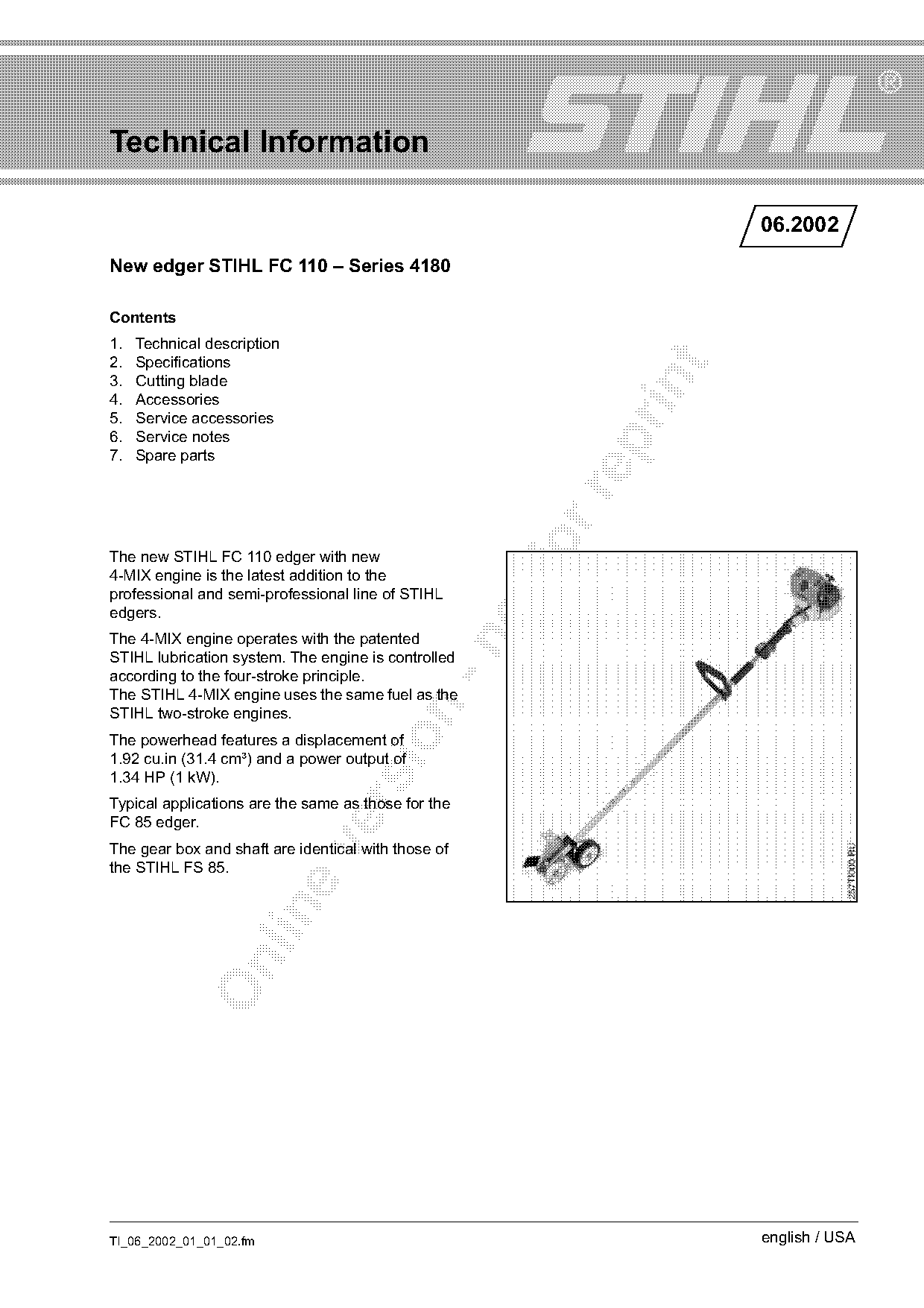
The new STIHL FC 110 edger with new
4-MIX engine is the latest addition to the
professional and semi-professional line of STIHL
edgers.
The 4-MIX engine operates with the patented

STIHL lubrication system. The engine is controlled
according to the four-stroke principle.
The STIHL 4-MIX engine uses the same fuel as the

STIHL two-stroke engines.

The powerhead features a displacement of
1.92 cu.in (31.4 cm³) and a power output of
1.34 HP (1 kW).
Typical applications are the same as those for the

FC 85 edger.

The gear box and shaft are identical with those of
the STIHL FS 85.

TI_06_2002_01_01_02.fm                                             english / USA
Page 2 of 12
Text of page 2 — search, copy, screen readers
Page 2                                                                             Technical Information 06.2002

1.     Technical description                                     1.1.2 Engine control

1.1    STIHL 4-MIX engine
The 4-MIX engine works with mixed lubrication.                                                           7
Unlike a conventional four-stroke engine,
the 4-MIX engine does not have any supply of oil in
the crankcase. The engine is lubricated entirely with
a mixture of gasoline and engine oil.                                      1                             2
This design yields the following advantages:                                                             6
.     Same fuel as two-stroke STIHL products
                                                                                                         5

.     Lower fuel consumption

.     Can be operated in all positions
                                                                                                         4
.     Good acceleration

.     Compact size – attractive design
.     Advantageous power-to-weight ratio                                                                 3

                                                                                                                   254TI011 KN
.     Easy maintenance – easy to service
.     Automatic compression release

1.1.1 Engine design
                                                                 .       fo
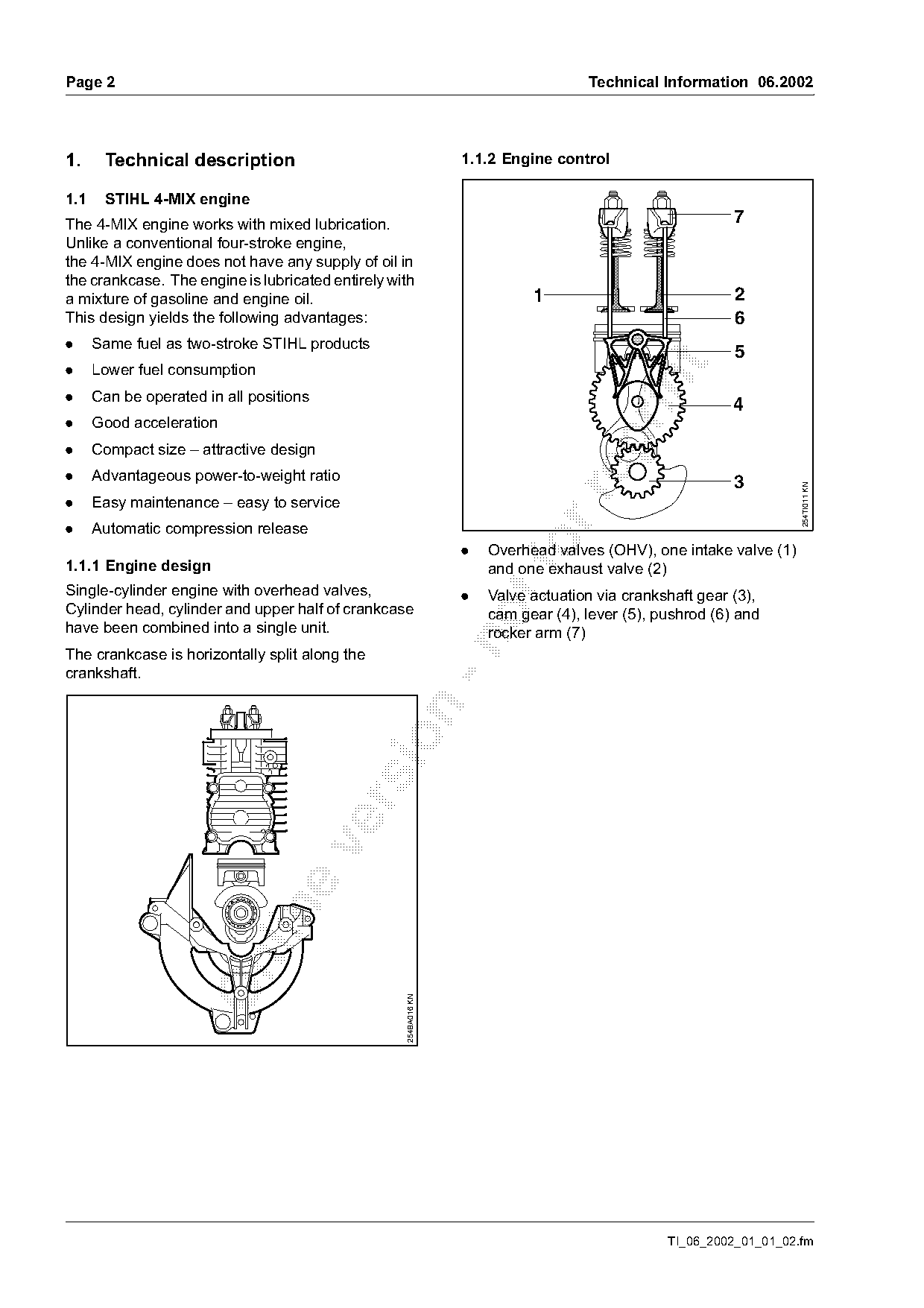
                                                                     Overhead valves (OHV), one intake valve (1)
                                                                     and one exhaust valve (2)
Single-cylinder engine with overhead valves,                     .   Valve actuation via crankshaft gear (3),
Cylinder head, cylinder and upper half of crankcase                  cam gear (4), lever (5), pushrod (6) and
have been combined into a single unit.                               rocker arm (7)

The crankcase is horizontally split along the
crankshaft.

                                                   254BA016 KN

                                                                                               TI_06_2002_01_01_02.fm
Page 3 of 12
Text of page 3 — search, copy, screen readers
Technical Information 06.2002                                                                                    Page 3

1.1.3 Engine lubrication
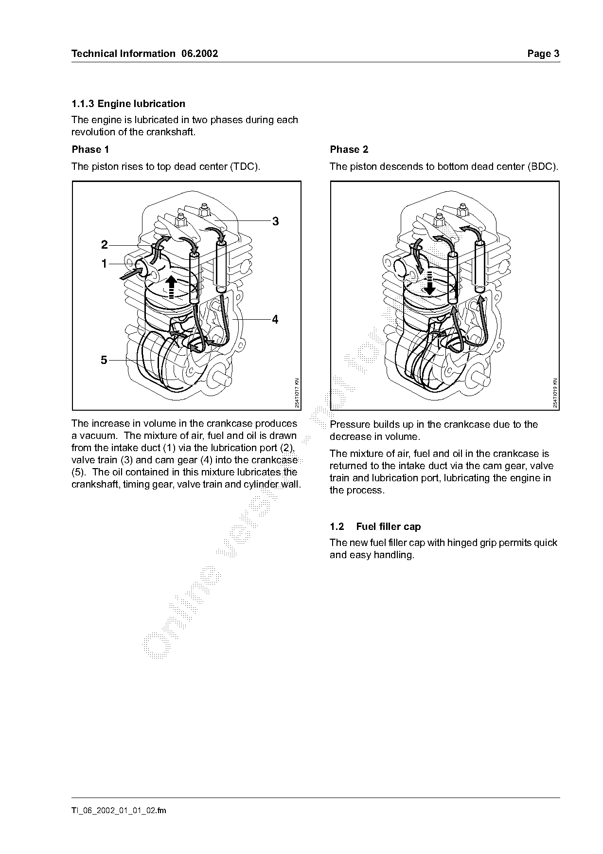
The engine is lubricated in two phases during each
revolution of the crankshaft.
Phase 1                                                            Phase 2
The piston rises to top dead center (TDC).                         The piston descends to bottom dead center (BDC).


       5                                                            fo
                                                     254TI017 KN

                                                                                                                       254TI019 KN

The increase in volume in the crankcase produces                   Pressure builds up in the crankcase due to the
a vacuum. The mixture of air, fuel and oil is drawn                decrease in volume.
from the intake duct (1) via the lubrication port (2),
                                                                   The mixture of air, fuel and oil in the crankcase is
valve train (3) and cam gear (4) into the crankcase

                                                                   returned to the intake duct via the cam gear, valve
(5). The oil contained in this mixture lubricates the
                                                                   train and lubrication port, lubricating the engine in

crankshaft, timing gear, valve train and cylinder wall.
                                                                   the process.

                                                                   1.2   Fuel filler cap
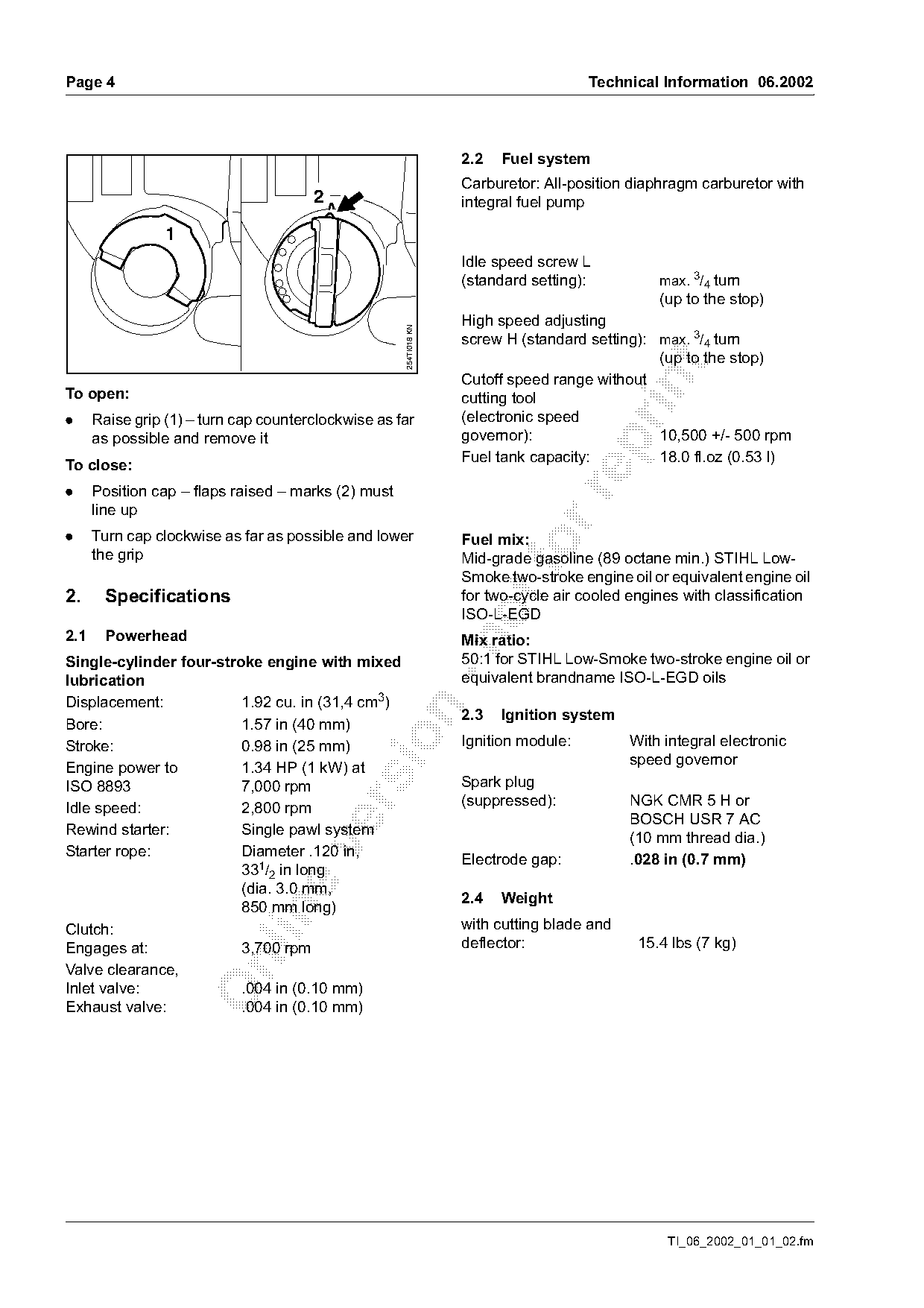
                                                                   The new fuel filler cap with hinged grip permits quick

                                                                   and easy handling.

TI_06_2002_01_01_02.fm
Page 4 of 12
Text of page 4 — search, copy, screen readers
Page 4                                                                                Technical Information 06.2002

                                                                   2.2   Fuel system
                                                                   Carburetor: All-position diaphragm carburetor with
                                       2                           integral fuel pump

                 1
                                                                   Idle speed screw L
                                                                   (standard setting):          max. 3/4 turn
                                                                                                (up to the stop)
                                                                   High speed adjusting

                                                     254TI018 KN
                                                                   screw H (standard setting): max. 3/4 turn
                                                                                               (up to the stop)

                                                                   Cutoff speed range without

To open:                                                           cutting tool
.     Raise grip (1) – turn cap counterclockwise as far            (electronic speed
      as possible and remove it                                    governor):                  10,500 +/- 500 rpm

                                                                   Fuel tank capacity:         18.0 fl.oz (0.53 l)
To close:
.     Position cap – flaps raised – marks (2) must

      line up
.     Turn cap clockwise as far as possible and lower              Fuel mix:
      the grip                                                             fo
                                                                   Mid-grade gasoline (89 octane min.) STIHL Low-
                                                                   Smoke two-stroke engine oil or equivalent engine oil
2.      Specifications                                             for two-cycle air cooled engines with classification
                                                                   ISO-L-EGD
2.1     Powerhead                                                  Mix ratio:

Single-cylinder four-stroke engine with mixed                      50:1 for STIHL Low-Smoke two-stroke engine oil or
lubrication                                                        equivalent brandname ISO-L-EGD oils
Displacement:            1.92 cu. in (31,4 cm3)

                                                                   2.3   Ignition system
Bore:                    1.57 in (40 mm)

Stroke:                  0.98 in (25 mm)                           Ignition module:         With integral electronic
                                                                                            speed governor
Engine power to          1.34 HP (1 kW) at
ISO 8893                 7,000 rpm                                 Spark plug
                                                                   (suppressed):            NGK CMR 5 H or

Idle speed:              2,800 rpm
                                                                                            BOSCH USR 7 AC
Rewind starter:          Single pawl system                                                 (10 mm thread dia.)

Starter rope:            Diameter .120 in,                         Electrode gap:           .028 in (0.7 mm)
                         331/2 in long
                         (dia. 3.0 mm,
                                                                   2.4   Weight
                         850 mm long)

Clutch:                                                            with cutting blade and
Engages at:              3,700 rpm                                 deflector:                15.4 lbs (7 kg)

Valve clearance,
Inlet valve:             .004 in (0.10 mm)
Exhaust valve:           .004 in (0.10 mm)

                                                                                                 TI_06_2002_01_01_02.fm
Page 5 of 12
Text of page 5 — search, copy, screen readers
Technical Information 06.2002                                                        Page 5

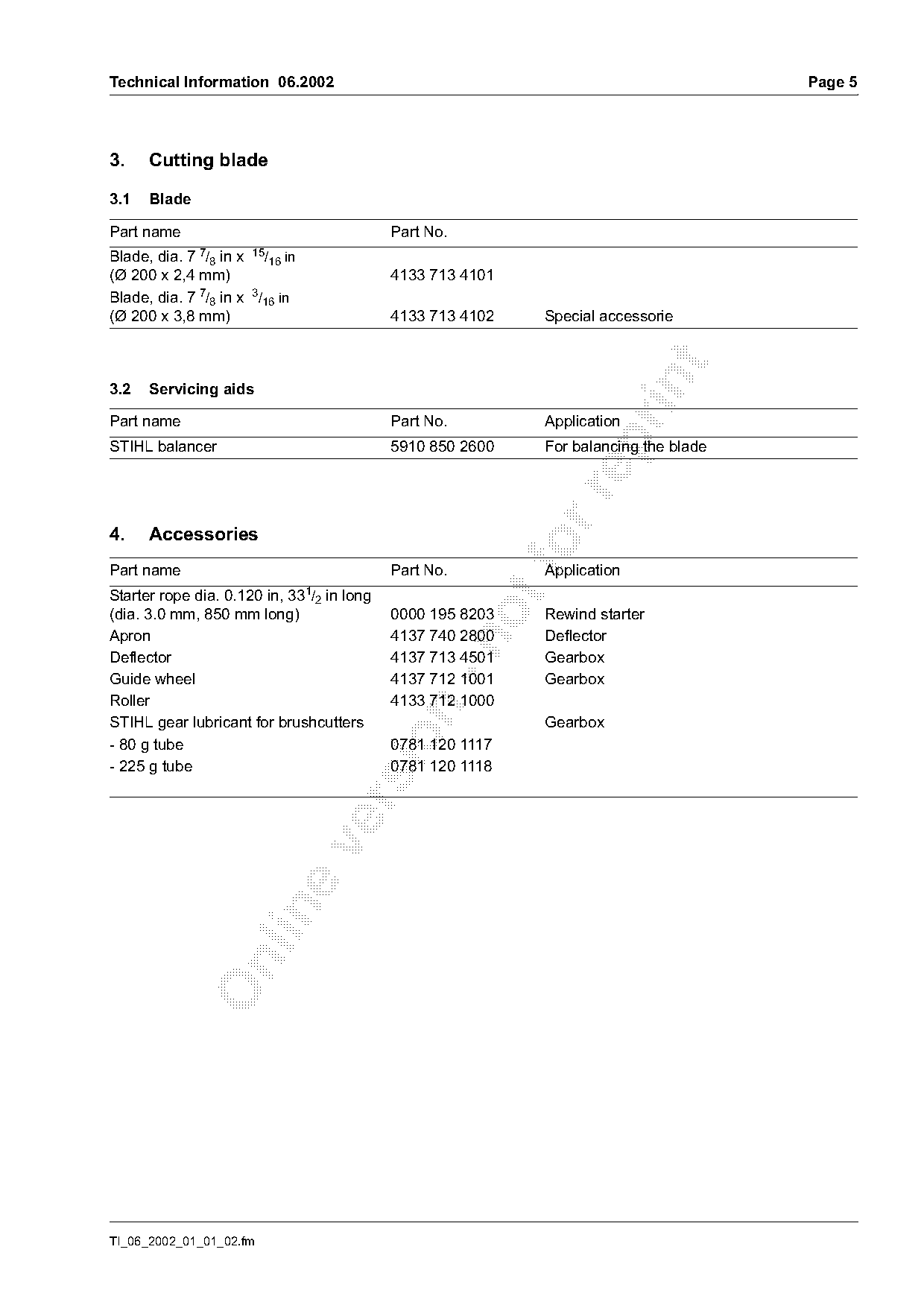
3.    Cutting blade

3.1   Blade

Part name                                  Part No.
Blade, dia. 7 7        15
               /8 in x /16 in
(Ø 200 x 2,4 mm)                           4133 713 4101
Blade, dia. 7 7/8 in x 3/16 in
(Ø 200 x 3,8 mm)                           4133 713 4102   Special accessorie

3.2   Servicing aids

Part name                                  Part No.        Application

STIHL balancer                             5910 850 2600   For balancing the blade

4.    Accessories
Part name                                  Part No.
                                                           Application
                                 1/
Starter rope dia. 0.120 in, 33 2 in long
(dia. 3.0 mm, 850 mm long)                 0000 195 8203   Rewind starter
Apron                                      4137 740 2800   Deflector

Deflector                                  4137 713 4501   Gearbox
Guide wheel                                4137 712 1001   Gearbox
Roller                                     4133 712 1000

STIHL gear lubricant for brushcutters                      Gearbox

- 80 g tube                                0781 120 1117
- 225 g tube                               0781 120 1118

TI_06_2002_01_01_02.fm
Page 6 of 12
Text of page 6 — search, copy, screen readers
Page 6                                                                       Technical Information 06.2002

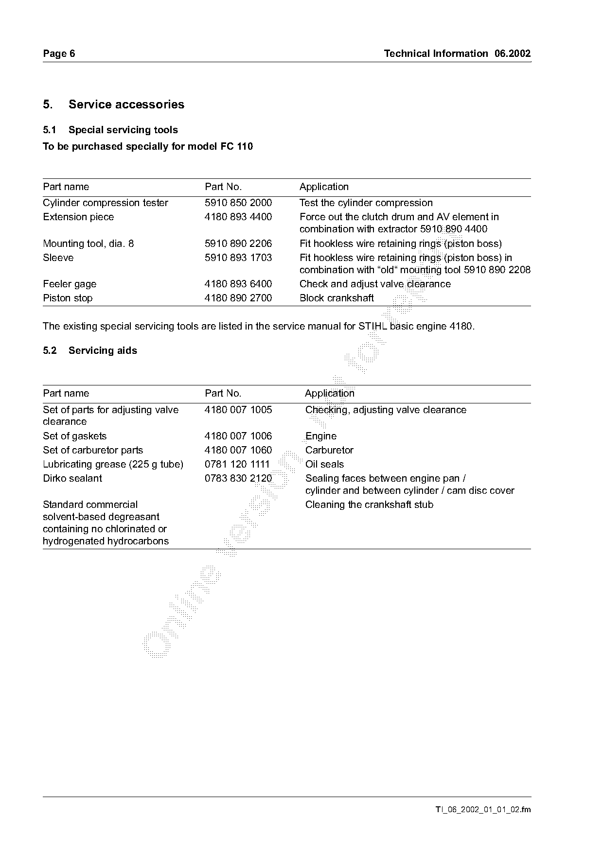
5.    Service accessories

5.1   Special servicing tools
To be purchased specially for model FC 110

Part name                           Part No.              Application
Cylinder compression tester         5910 850 2000         Test the cylinder compression
Extension piece                     4180 893 4400         Force out the clutch drum and AV element in
                                                          combination with extractor 5910 890 4400

Mounting tool, dia. 8               5910 890 2206         Fit hookless wire retaining rings (piston boss)

Sleeve                              5910 893 1703         Fit hookless wire retaining rings (piston boss) in
                                                          combination with “old“ mounting tool 5910 890 2208
Feeler gage                         4180 893 6400         Check and adjust valve clearance

Piston stop                         4180 890 2700         Block crankshaft

The existing special servicing tools are listed in the service manual for STIHL basic engine 4180.

5.2   Servicing aids
Part name                           Part No.               Application
Set of parts for adjusting valve    4180 007 1005          Checking, adjusting valve clearance

clearance
Set of gaskets                      4180 007 1006          Engine
Set of carburetor parts             4180 007 1060          Carburetor

Lubricating grease (225 g tube)     0781 120 1111          Oil seals
Dirko sealant                       0783 830 2120          Sealing faces between engine pan /

                                                           cylinder and between cylinder / cam disc cover
Standard commercial                                        Cleaning the crankshaft stub
solvent-based degreasant

containing no chlorinated or
hydrogenated hydrocarbons

                                                                                         TI_06_2002_01_01_02.fm
Page 7 of 12
Text of page 7 — search, copy, screen readers
Technical Information 06.2002                                                                                   Page 7

6.     Service notes
Specific national safety regulations and the safety
instructions in the User Manual must be observed
when starting the machine.                                                                   6

6.1    Check valve clearance
                                                                                             5
The valve clearance should be checked once after
approx. 135 hours of operation and adjusted if
necessary. The valve clearance is checked and                                                           4

                                                                                                                      254TI002 KN
adjusted when the engine is cold.                                                    4
Kit 4180 007 1005 "Parts for adjusting valve

clearance" can be used for this purpose. The kit

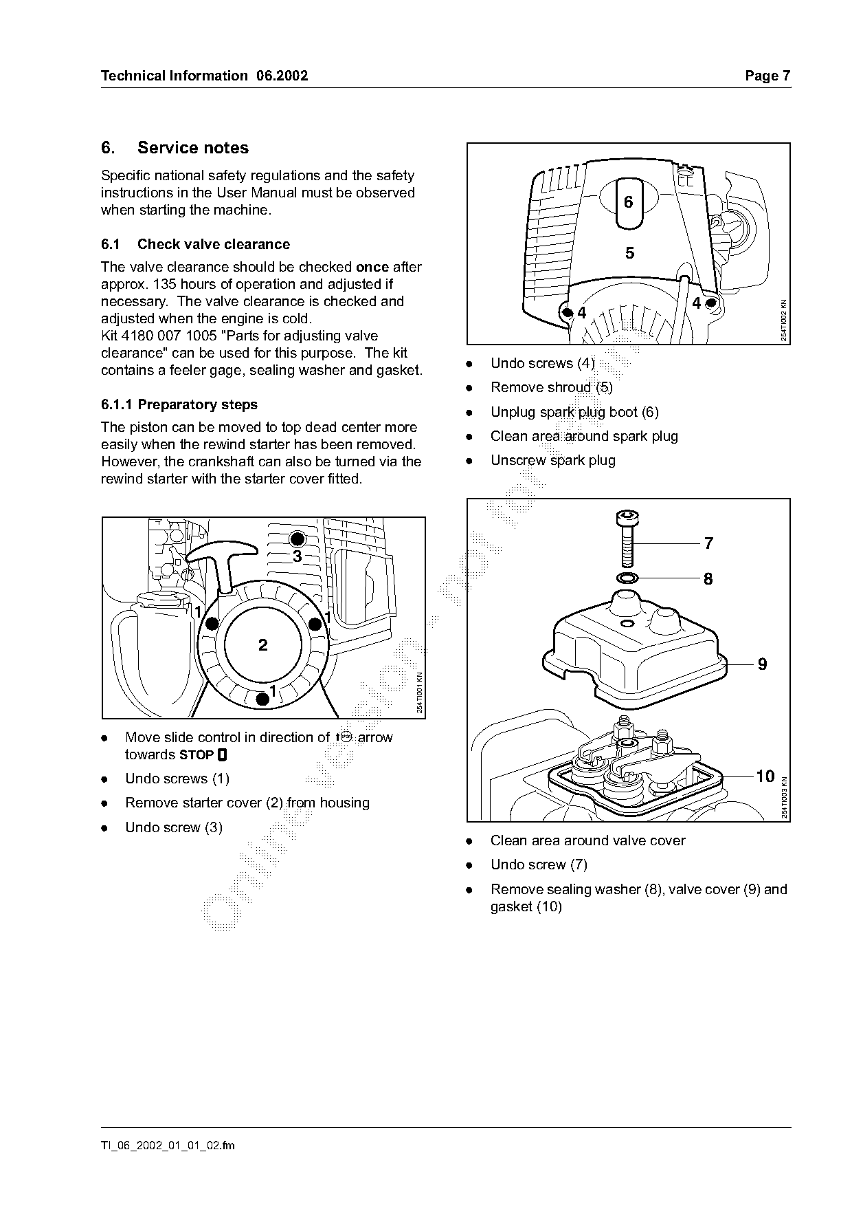
contains a feeler gage, sealing washer and gasket.                  .   Undo screws (4)
                                                                    .   Remove shroud (5)
6.1.1 Preparatory steps

                                                                    .   Unplug spark plug boot (6)
The piston can be moved to top dead center more
                                                                    .   Clean area around spark plug
easily when the rewind starter has been removed.

However, the crankshaft can also be turned via the                  .   Unscrew spark plug
rewind starter with the starter cover fitted.

                                                                                                            7
                                  3
                                                                                                            8

                1                     1
                          2

                                                                                                                 9
                                                      254TI001 KN


.     Move slide control in direction of c arrow

      towards STOP $
.     Undo screws (1)                                                                                            10

                                                                                                                       254TI003 KN

.     Remove starter cover (2) from housing
.     Undo screw (3)
                                                                    .   Clean area around valve cover

                                                                    .   Undo screw (7)
                                                                    .   Remove sealing washer (8), valve cover (9) and

                                                                        gasket (10)

TI_06_2002_01_01_02.fm
Page 8 of 12
Text of page 8 — search, copy, screen readers
Page 8                                                                            Technical Information 06.2002

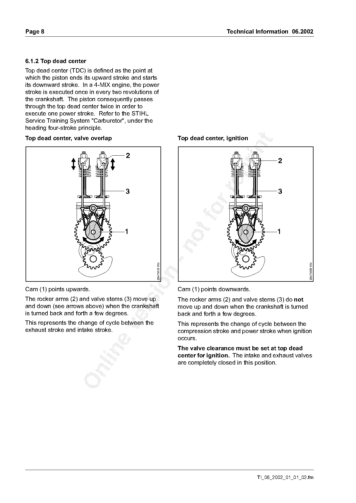
6.1.2 Top dead center
Top dead center (TDC) is defined as the point at
which the piston ends its upward stroke and starts
its downward stroke. In a 4-MIX engine, the power
stroke is executed once in every two revolutions of
the crankshaft. The piston consequently passes
through the top dead center twice in order to
execute one power stroke. Refer to the STIHL
Service Training System "Carburetor", under the
heading four-stroke principle.
Top dead center, valve overlap                                  Top dead center, ignition

                                      2
                                                                                                     2

                                      3                                                              3

                                     1                                                               1
                                                  254TI010 KN

                                                                                                                 254TI009 KN

Cam (1) points upwards.                                         Cam (1) points downwards.
The rocker arms (2) and valve stems (3) move up                 The rocker arms (2) and valve stems (3) do not
and down (see arrows above) when the crankshaft                 move up and down when the crankshaft is turned

is turned back and forth a few degrees.                         back and forth a few degrees.
This represents the change of cycle between the                 This represents the change of cycle between the

exhaust stroke and intake stroke.                               compression stroke and power stroke when ignition
                                                                occurs.
                                                                The valve clearance must be set at top dead

                                                                center for ignition. The intake and exhaust valves
                                                                are completely closed in this position.

                                                                                             TI_06_2002_01_01_02.fm
Page 9 of 12
Text of page 9 — search, copy, screen readers
Technical Information 06.2002                                                                                      Page 9

6.1.3 Determine top dead center                                      6.1.4 Check valve clearance

                     2                                                                                             2
                                                                                                                    1
                           1                                                                                         3

                                                       254TI008 KN

                                                                                                                       2
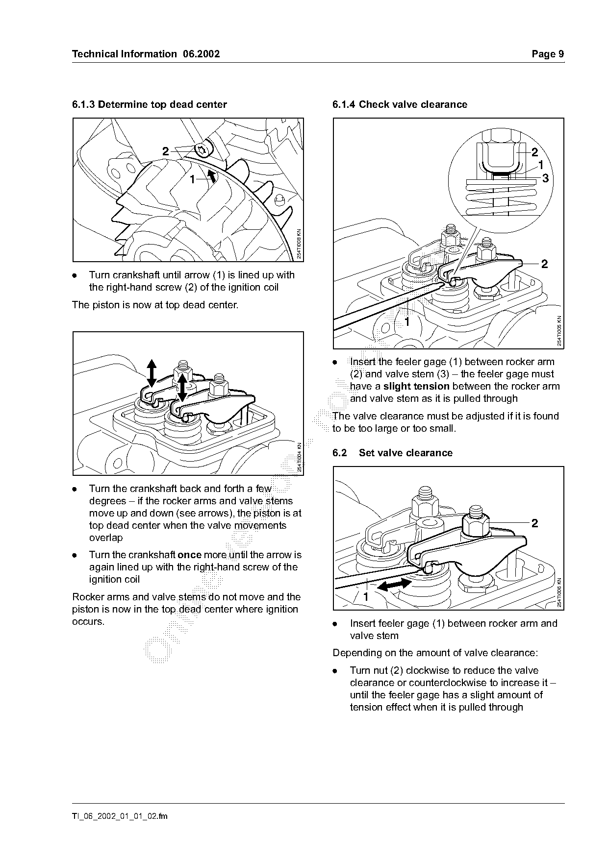
.   Turn crankshaft until arrow (1) is lined up with
    the right-hand screw (2) of the ignition coil

The piston is now at top dead center.

                                                                                                                            254TI005 KN
                                                                                       1

                                                                     .   foInsert the feeler gage (1) between rocker arm
                                                                           (2) and valve stem (3) – the feeler gage must
                                                                           have a slight tension between the rocker arm
                                                                           and valve stem as it is pulled through
                                                                     The valve clearance must be adjusted if it is found

                                                                     to be too large or too small.
                                                       254TI004 KN

                                                                     6.2    Set valve clearance

.   Turn the crankshaft back and forth a few
    degrees – if the rocker arms and valve stems
    move up and down (see arrows), the piston is at
    top dead center when the valve movements                                                                       2

    overlap
.   Turn the crankshaft once more until the arrow is

    again lined up with the right-hand screw of the
    ignition coil
                                                                                                                            254TI006 KN

Rocker arms and valve stems do not move and the                              1

piston is now in the top dead center where ignition
occurs.                                                              .     Insert feeler gage (1) between rocker arm and

                                                                           valve stem
                                                                     Depending on the amount of valve clearance:
                                                                     .     Turn nut (2) clockwise to reduce the valve
                                                                           clearance or counterclockwise to increase it –
                                                                           until the feeler gage has a slight amount of
                                                                           tension effect when it is pulled through

TI_06_2002_01_01_02.fm
Page 10 of 12
Text of page 10 — search, copy, screen readers
Page 10                                                                         Technical Information 06.2002

.     Turn the crankshaft through two turns until the
      arrow is once again lined up with the right-hand
      screw of the ignition coil
.     Check the valve clearance again and re-adjust if
      necessary

6.3     Assembly
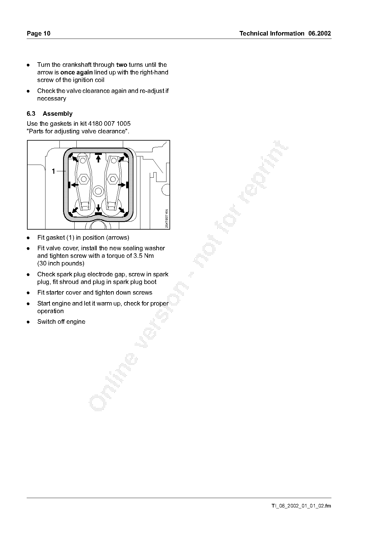
Use the gaskets in kit 4180 007 1005
"Parts for adjusting valve clearance".


                                                        254TI007 KN

.     Fit gasket (1) in position (arrows)
.     Fit valve cover, install the new sealing washer
      and tighten screw with a torque of 3.5 Nm

      (30 inch pounds)
.     Check spark plug electrode gap, screw in spark
      plug, fit shroud and plug in spark plug boot

.     Fit starter cover and tighten down screws

.     Start engine and let it warm up, check for proper
      operation
.     Switch off engine

                                                                                          TI_06_2002_01_01_02.fm
Page 11 of 12
Text of page 11 — search, copy, screen readers
Technical Information 06.2002                                                                          Page 11

6.4   Tightening torques
The tightening torques for model FC 110
                                                         Code   Type of Repair                        FC 110
are listed in the service manual for the
STIHL basic engine 4180.                                  1     Crankshaft                             1.5
                                                          2
6.5   Service note                                        3     Crankcase Sealing                      1.3
The service manual for the STIHL basic                    4     Crankshaft Seals (includes             0.9
engine 4180 is available for servicing and repair of            pressure & vacuum testing)
the STIHL FC 110.                                         5     Cylinder and/or Piston, replace        1.8
Refer also to the STIHL Service Training System                 valves
"Troubleshooting" available on CD-ROM.                    6     Ignition Module                        0.4

                                                          7     Fuel Hose                              0.4
6.6   Repair times
                                                          8     Replace Gear Box/Arbor Assy.           0.4
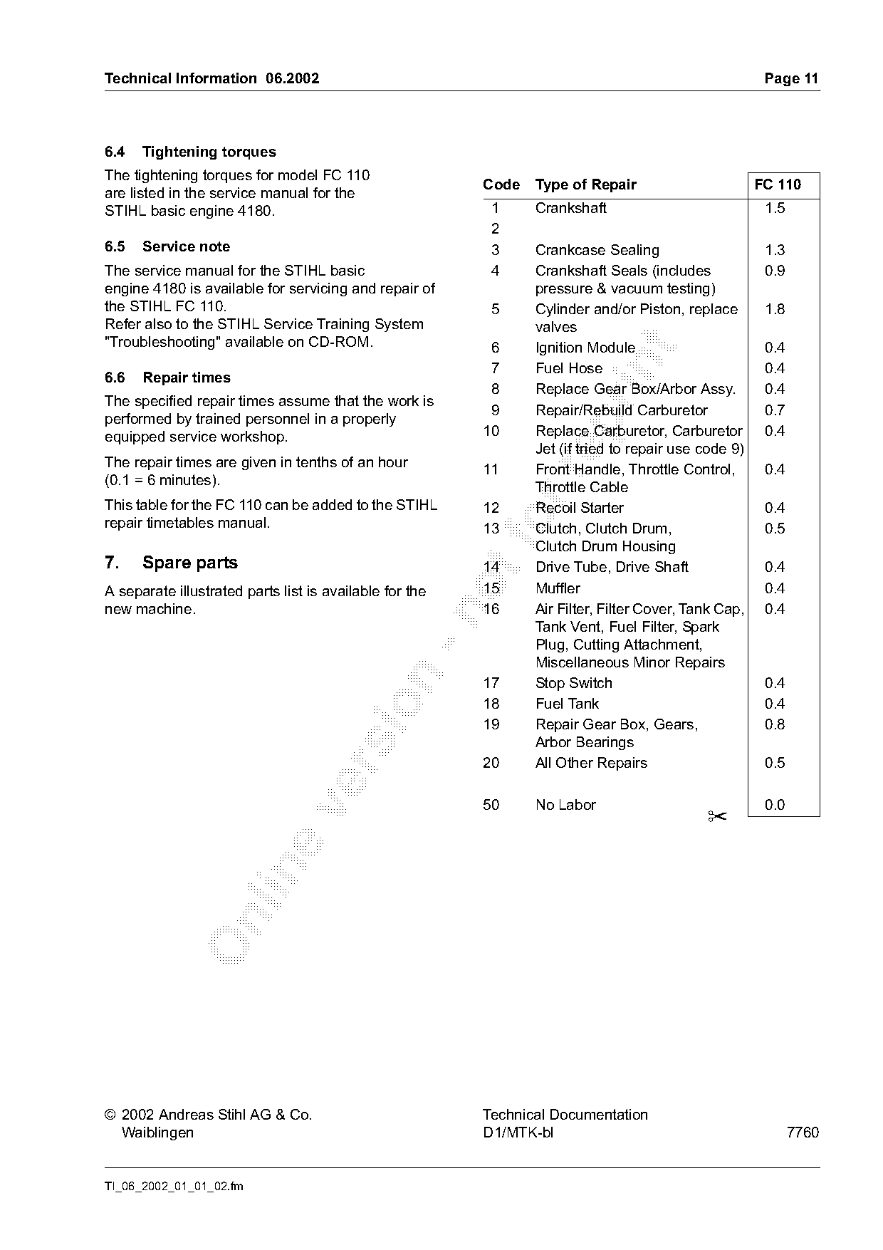
The specified repair times assume that the work is
                                                          9     Repair/Rebuild Carburetor              0.7
performed by trained personnel in a properly

equipped service workshop.                               10     Replace Carburetor, Carburetor         0.4
                                                                Jet (if tried to repair use code 9)
The repair times are given in tenths of an hour          11     Front Handle, Throttle Control,        0.4

(0.1 = 6 minutes).                                              Throttle Cable
This table for the FC 110 can be added to the STIHL      12     Recoil Starter                         0.4
repair timetables manual.                                 fo
                                                         13     Clutch, Clutch Drum,
                                                                Clutch Drum Housing
                                                                                                       0.5

7.    Spare parts                                        14     Drive Tube, Drive Shaft                0.4
A separate illustrated parts list is available for the   15     Muffler                                0.4
new machine.                                             16     Air Filter, Filter Cover, Tank Cap,    0.4

                                                                Tank Vent, Fuel Filter, Spark
                                                                Plug, Cutting Attachment,
                                                                Miscellaneous Minor Repairs

                                                         17     Stop Switch                            0.4
                                                         18     Fuel Tank                              0.4

                                                         19     Repair Gear Box, Gears,                0.8
                                                                Arbor Bearings
                                                         20     All Other Repairs                      0.5

                                                         50     No Labor                               0.0

                                                                                            ✂

© 2002 Andreas Stihl AG & Co.                            Technical Documentation
  Waiblingen                                             D1/MTK-bl                                           7760

TI_06_2002_01_01_02.fm
Page 12 of 12

Text of page 12 — search, copy, screen readers
Page 12                         Technical Information 06.2002

                                          TI_06_2002_01_01_02.fm
Most of these PDFs embed fonts with a shifted character map, so the text above was recovered rather than copied — read it as a faithful but imperfect transcription, and treat the page image above each block as the authority where the two disagree — the figures exist only there, because they are vector drawings that text extraction cannot keep.