Technical Information · issue 13 of 2002
New drill
IssueTI 13/2002
Full text
Page 1 of 6
Text of page 1 — search, copy, screen readers
Technical Information

                                                                                            13.2002
New STIHL BT 45 drill – Series 4314

Contents
1.   Technical description
2.   Specifications

3.   Drills

4.   Set of parts and accessories
5.   Service accessories and special tools
6.   Service note

7.   Spare parts

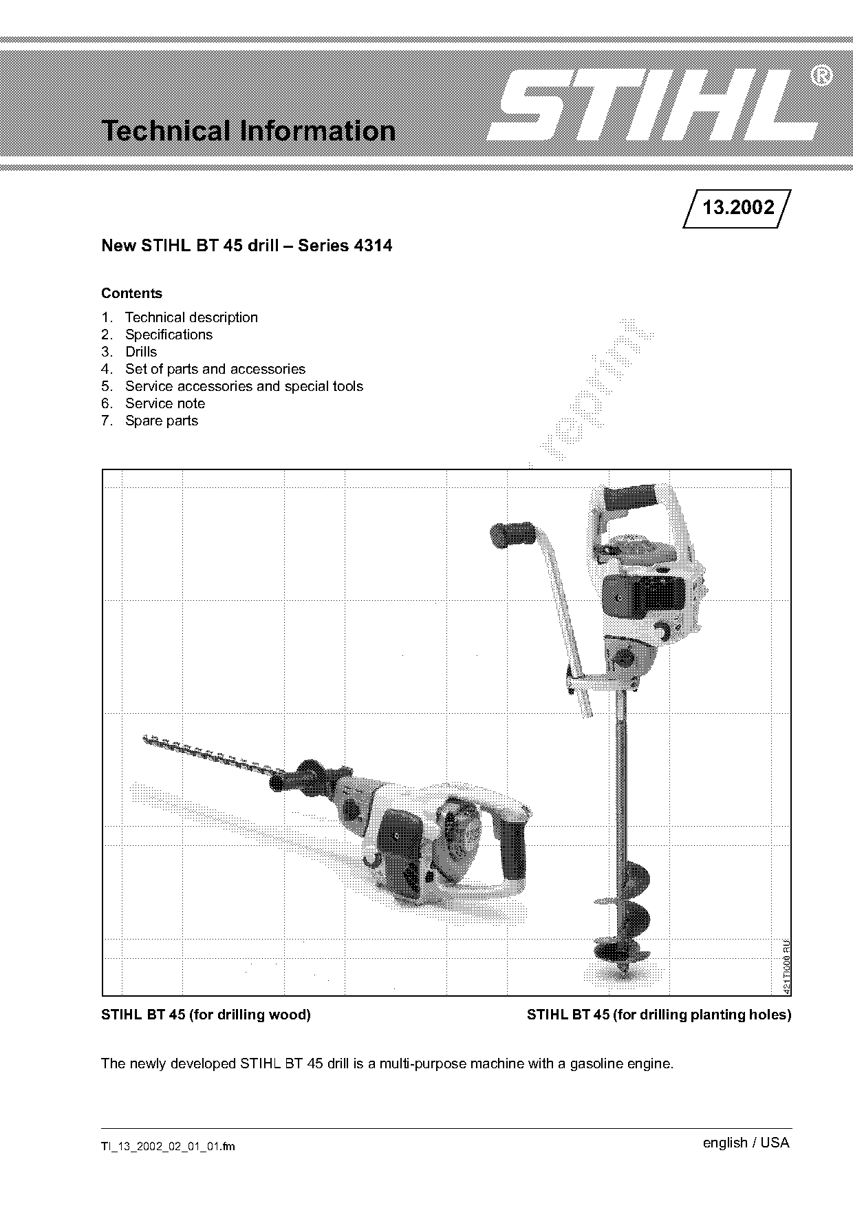
STIHL BT 45 (for drilling wood)                                  STIHL BT 45 (for drilling planting holes)

The newly developed STIHL BT 45 drill is a multi-purpose machine with a gasoline engine.

TI_13_2002_02_01_01.fm                                                                      english / USA
Page 2 of 6
Text of page 2 — search, copy, screen readers
Page 2                                                                         Technical Information 13.2002

The machine can be adapted to certain applications        Gear mechanism
by combining the unit with different handles and
                                                          .     Gearbox with four gear positions: 1, 2, Reverse,
attachments. For this purpose, adapter sets are
                                                                Neutral
optionally available for drilling wood and for drilling
planting holes. This opens up a large range of            .     Integrated slip clutch
possible uses in the following areas (examples):          .     Light metal housing
.    Building trade, joinery, wood construction (not      .     Lubricated for life, maintenance-free
     in closed premises)
.    Landscape gardening (planting)
.    Agriculture and forestry                             2.      Specifications

.    Municipal service crews

                                                          2.1     Powerhead
.    Construction of sports and playground facilities
                                                          2.1.1 Engine

1.     Technical description
                                                          STIHL single-cylinder two-stroke engine

The machine is powered by the "Basic“ 4140 engine         Displacement:           27.2 cm3 (1.66 cu. in.)
which is used in many STIHL power tool series
                                                          Bore:                   34 mm (1.34 in.)
(such as: FS 45, FS 55, FC 55, HS 45, HL 45, BG
45, BG 55, SH 55, SH 85).                                 Stroke:   fo
                                                          Engine power to
                                                                                  30 mm (1.18 in.)
                                                                                  0.8 kW (1.1 HP)
Cylinder
                                                          ISO 8893:               @ 7000 rpm
.    Four-port technology (better mixture control)        Idle speed:             2800 rpm
.    Large cooling air surface                            Rewind starter:         Single pawl system

Crankshaft                                                Starter rope:           Dia. 3.0 mm,
                                                                                  41 3/4“ (1060 mm) long
.    “Built up“ design                                    Clutch:                 Centrifugal clutch

.    Mounted in bearings at both ends                     Clutch engages at:      4000 rpm

Carburetor
                                                          2.1.2 Fuel system
.    With three adjusting screws (H, L, LA), H-screw
                                                          Carburetor: All-position diaphragm carburetor with
     with cap to limit the adjustment range
                                                          integral fuel pump

.    With manually actuated fuel pump (purger)
Air filter

                                                          Low speed adjusting screw L
.    Multi-layer (felt, foam)
                                                          (standard setting):          1 turn open
Exhaust muffler                                           High speed adjusting screw H

.    Two-chamber muffler with spark arresting             (standard setting):          Open fully
     screen                                                                            (max. 3/4 turn)
                                                          Fuel tank capacity:          0.25 l (8.5 oz.)
Clutch

.    Three clutch shoes without linings                   2.1.3 Ignition system
Fuel tank                                                 Ignition module:            With integrated electronic
.    Integrated into the housing for protection                                       speed limiter
.    Fuel filler cap can be opened and closed without     Spark plug
     tools                                                (suppressed):               NGK BPMR 7 A
                                                          Electrode gap:              0.5 mm (.020 in)
Vibration damping
.    AV system with four rubber buffers

                                                                                           TI_13_2002_02_01_01.fm
Page 3 of 6
Text of page 3 — search, copy, screen readers
Technical Information 13.2002                                                                                    Page 3

2.2   Gearbox                                                      The planting hole drills are made for planting
Type: Spur gear, straight-toothed                                  applications only. Drill heads and cutters can be
                                                                   replaced when worn and the cutters reversed. The
Switch         Transmission    Spindle speed at                    drills are available in the following sizes:
position       ratio           n = 7000 rpm
                               (in rpm)
1              11.3 : 1        620                                 Planting hole drills             Part No.
2              3.8 : 1         1840                                Dia. 75 mm (3"), 595 mm
R              12.7 : 1        550 (reverse gear)                  (23“) long                       4314 680 1903
N              Neutral position (idle)                             Dia. 100 mm (4"), 595 mm
                                                                   (23“) long                       4314 680 1904

2.3   Weight                                                       Dia. 127 mm (5"), 595 mm

Without set of parts and drill:       10.6 lbs (4.8 kg)            (23“) long                       4314 680 1905

2.4   Dimensions

                                                                   Importand note: planting hole drills are designed to
Without set of parts and drill
                                                                   be used for drilling shallow planting holes in loose,
Length 17.5 in. (445 mm)                                           cultivated soil. Do not use as an earth auger (e.g.

Width 9.1 in. (230 mm)                                             drilling post holes). Any such use will lead to
                                                                   accelerated wear and premature failure of the
Height 9.1 in (230 mm)
                                                                   planting hole drill.

3.    Drills                                                       4.    Set of parts and accessories

                                                                   4.1   Set of parts for wood drills

           3                                  2

                                              1                                                             3
                                                     421TI001 KN


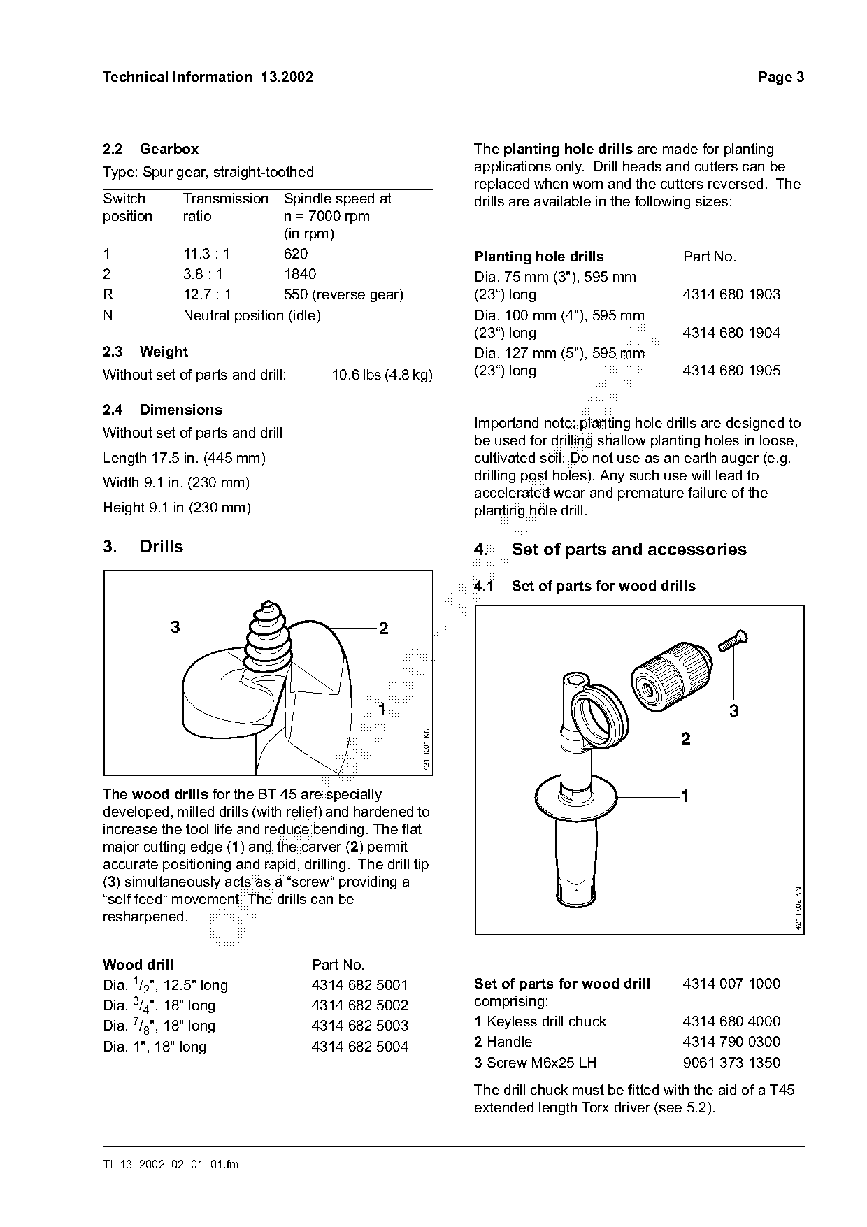
The wood drills for the BT 45 are specially

                                                                                                    1
developed, milled drills (with relief) and hardened to
increase the tool life and reduce bending. The flat
major cutting edge (1) and the carver (2) permit

accurate positioning and rapid, drilling. The drill tip
(3) simultaneously acts as a “screw“ providing a
                                                                                                                          421TI002 KN

“self feed“ movement. The drills can be

resharpened.

Wood drill                         Part No.
Dia. 1/2", 12.5" long              4314 682 5001                   Set of parts for wood drill      4314 007 1000
Dia. 3/4", 18" long                4314 682 5002                   comprising:
Dia. 7/8", 18" long                4314 682 5003                   1 Keyless drill chuck            4314 680 4000
Dia. 1", 18" long                  4314 682 5004                   2 Handle                         4314 790 0300
                                                                   3 Screw M6x25 LH                 9061 373 1350
                                                                   The drill chuck must be fitted with the aid of a T45
                                                                   extended length Torx driver (see 5.2).

TI_13_2002_02_01_01.fm
Page 4 of 6
Text of page 4 — search, copy, screen readers
Page 4                                                                                 Technical Information 13.2002

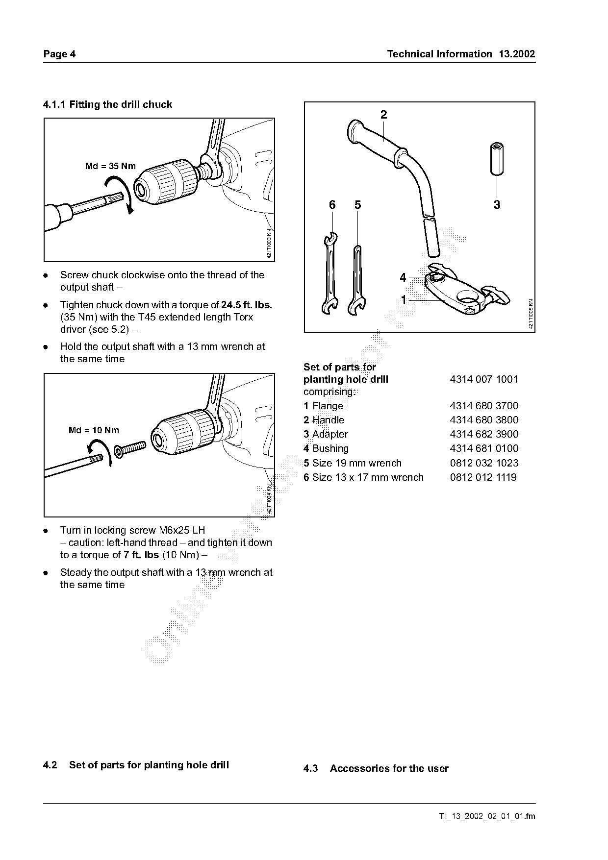
4.1.1 Fitting the drill chuck
                                                                                   2

           Md = 35 Nm

                                                                         6   5                               3

                                                     421TI003 KN

.     Screw chuck clockwise onto the thread of the                                       4
      output shaft –

.     Tighten chuck down with a torque of 24.5 ft. lbs.                                  1

                                                                                                                     421TI005 KN
      (35 Nm) with the T45 extended length Torx

      driver (see 5.2) –
.     Hold the output shaft with a 13 mm wrench at
      the same time                                                          fo
                                                                   Set of parts for
                                                                   planting hole drill              4314 007 1001
                                                                   comprising:
                                                                   1 Flange                         4314 680 3700
                                                                   2 Handle                         4314 680 3800

       Md = 10 Nm                                                  3 Adapter                        4314 682 3900
                                                                   4 Bushing                        4314 681 0100
                                                                   5 Size 19 mm wrench              0812 032 1023

                                                                   6 Size 13 x 17 mm wrench         0812 012 1119
                                               sio   421TI004 KN

.     Turn in locking screw M6x25 LH
      – caution: left-hand thread – and tighten it down
      to a torque of 7 ft. lbs (10 Nm) –

.     Steady the output shaft with a 13 mm wrench at
      the same time

4.2     Set of parts for planting hole drill                       4.3   Accessories for the user

                                                                                                 TI_13_2002_02_01_01.fm
Page 5 of 6
Text of page 5 — search, copy, screen readers
Technical Information 13.2002                                                                     Page 5


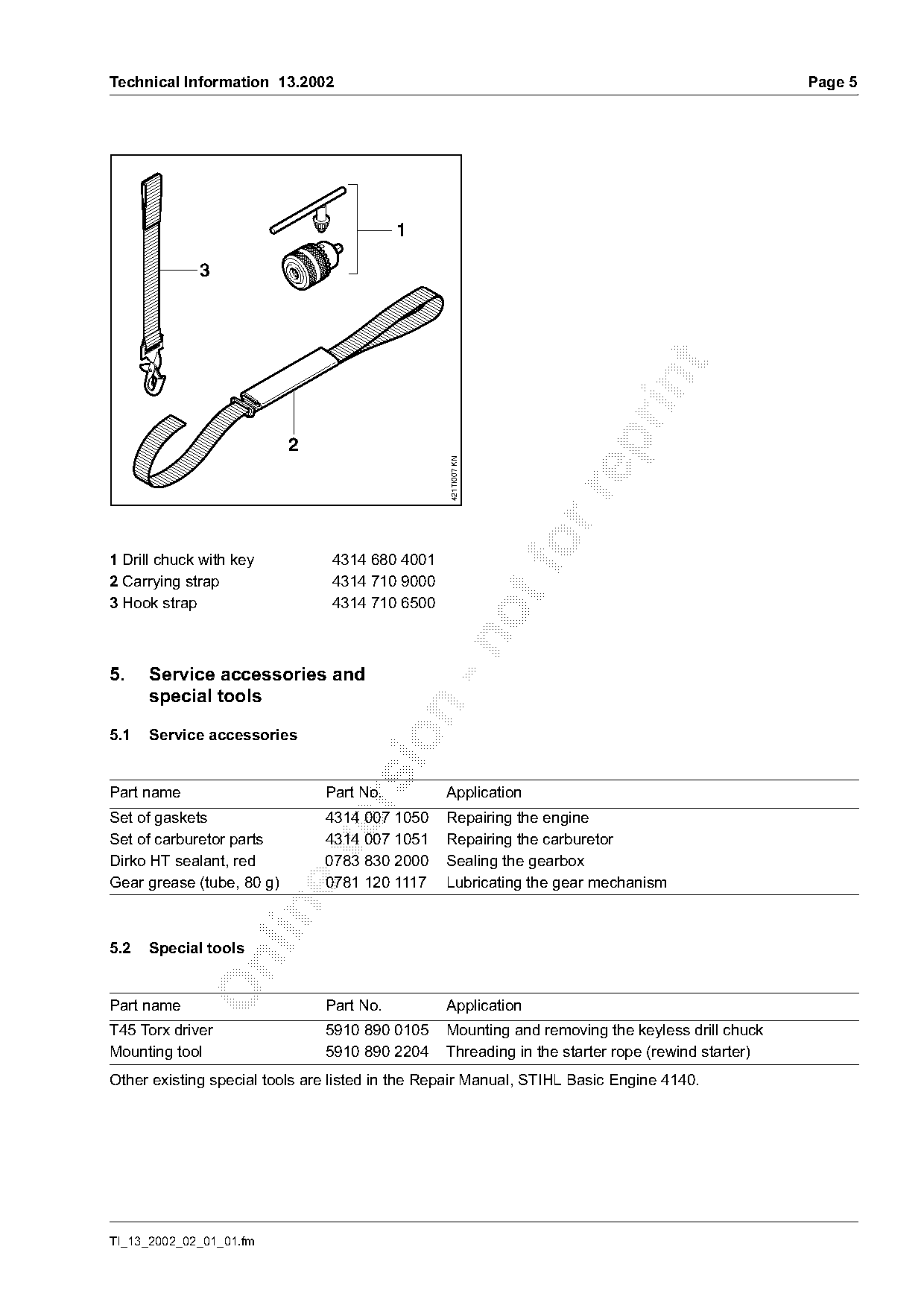
                           2                     421TI007 KN

1 Drill chuck with key          4314 680 4001
2 Carrying strap                4314 710 9000
3 Hook strap                    4314 710 6500

5.    Service accessories and
      special tools

5.1   Service accessories

Part name                      Part No.          Application

Set of gaskets                 4314 007 1050     Repairing the engine
Set of carburetor parts        4314 007 1051     Repairing the carburetor

Dirko HT sealant, red          0783 830 2000     Sealing the gearbox
Gear grease (tube, 80 g)       0781 120 1117     Lubricating the gear mechanism

5.2   Special tools

Part name                      Part No.          Application
T45 Torx driver                5910 890 0105     Mounting and removing the keyless drill chuck
Mounting tool                  5910 890 2204     Threading in the starter rope (rewind starter)
Other existing special tools are listed in the Repair Manual, STIHL Basic Engine 4140.

TI_13_2002_02_01_01.fm
Page 6 of 6
Text of page 6 — search, copy, screen readers
Page 6                                                                       Technical Information 13.2002

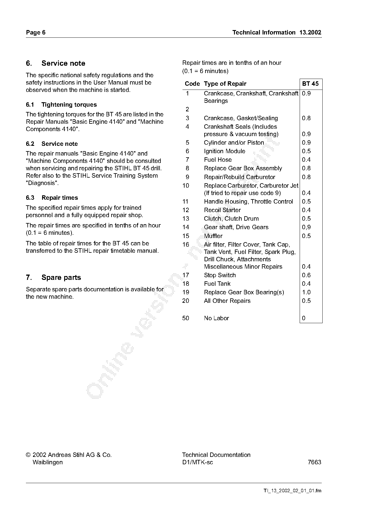
6.    Service note                                        Repair times are in tenths of an hour
                                                          (0.1 = 6 minutes)
The specific national safety regulations and the
safety instructions in the User Manual must be            Code Type of Repair                         BT 45
observed when the machine is started.
                                                           1      Crankcase, Crankshaft, Crankshaft 0.9
                                                                  Bearings
6.1   Tightening torques
                                                           2
The tightening torques for the BT 45 are listed in the
                                                           3      Crankcase, Gasket/Sealing           0.8
Repair Manuals "Basic Engine 4140" and "Machine
Components 4140".                                          4      Crankshaft Seals (Includes
                                                                  pressure & vacuum testing)          0.9
6.2   Service note                                         5      Cylinder and/or Piston              0.9

                                                           6      Ignition Module                     0.5

The repair manuals "Basic Engine 4140" and
"Machine Components 4140" should be consulted              7      Fuel Hose                           0.4
when servicing and repairing the STIHL BT 45 drill.        8      Replace Gear Box Assembly           0.8

Refer also to the STIHL Service Training System            9      Repair/Rebuild Carburetor           0.8
"Diagnosis".                                              10      Replace Carburetor, Carburetor Jet
                                                                  (If tried to repair use code 9)     0.4

6.3   Repair times
                                                          11      Handle Housing, Throttle Control 0.5
The specified repair times apply for trained              12      Recoil Starter                      0.4
personnel and a fully equipped repair shop.
The repair times are specified in tenths of an hour
                                                          13
                                                          14
                                                                  Clutch, Clutch Drum
                                                                  Gear shaft, Drive Gears
                                                                                                      0.5
                                                                                                      0,9
(0.1 = 6 minutes).
                                                          15      Muffler                             0.5
The table of repair times for the BT 45 can be            16      Air filter, Filter Cover, Tank Cap,
transferred to the STIHL repair timetable manual.                 Tank Vent, Fuel Filter, Spark Plug,

                                                                  Drill Chuck, Attachments
                                                                  Miscellaneous Minor Repairs         0.4
7.    Spare parts                                         17      Stop Switch                         0.6

                                                          18      Fuel Tank                           0.4
Separate spare parts documentation is available for

                                                          19      Replace Gear Box Bearing(s)         1.0
the new machine.
                                                          20      All Other Repairs                   0.5

                                                          50      No Labor                            0

© 2002 Andreas Stihl AG & Co.                             Technical Documentation
  Waiblingen                                              D1/MTK-sc                                       7663

                                                                                        TI_13_2002_02_01_01.fm
Most of these PDFs embed fonts with a shifted character map, so the text above was recovered rather than copied — read it as a faithful but imperfect transcription, and treat the page image above each block as the authority where the two disagree — the figures exist only there, because they are vector drawings that text extraction cannot keep.