Technical Information · issue 24 of 2002
Control Handle with Throttle Cable; Rewind Starter
Model FH 75 Power Scythe – Series 4230
IssueTI 24/2002
Full text
Page 1 of 10
Text of page 1 — search, copy, screen readers
Technical Information

                                                                                              24.2002
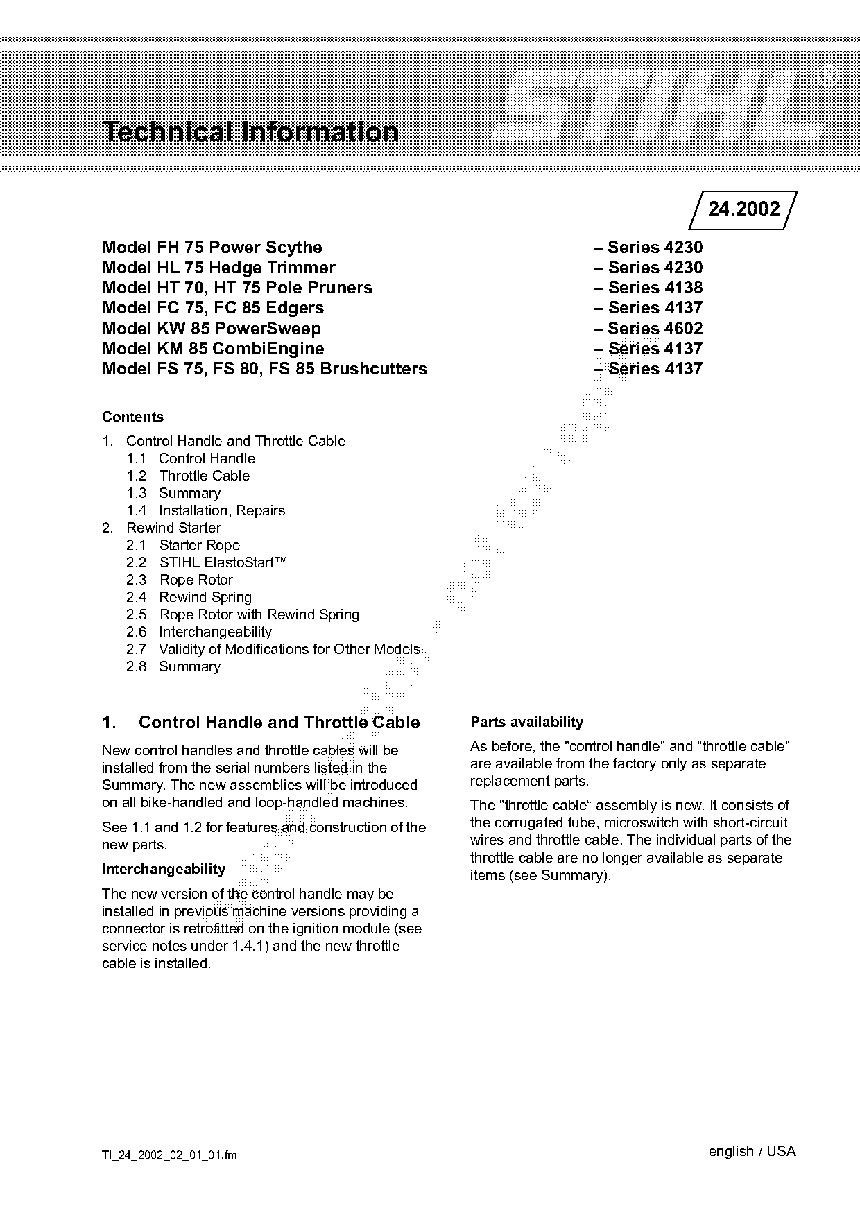
Model FH 75 Power Scythe                                                    – Series 4230
Model HL 75 Hedge Trimmer                                                   – Series 4230
Model HT 70, HT 75 Pole Pruners                                             – Series 4138
Model FC 75, FC 85 Edgers                                                   – Series 4137
Model KW 85 PowerSweep                                                      – Series 4602

Model KM 85 CombiEngine                                                     – Series 4137

Model FS 75, FS 80, FS 85 Brushcutters                                      – Series 4137

Contents
1. Control Handle and Throttle Cable
   1.1 Control Handle

   1.2 Throttle Cable
   1.3 Summary
   1.4 Installation, Repairs
2. Rewind Starter
   2.1 Starter Rope
   2.2 STIHL ElastoStart™
   2.3 Rope Rotor
   2.4 Rewind Spring

   2.5 Rope Rotor with Rewind Spring
   2.6 Interchangeability
   2.7 Validity of Modifications for Other Models

   2.8 Summary

1.   Control Handle and Throttle Cable                 Parts availability
                                                       As before, the "control handle" and "throttle cable"

New control handles and throttle cables will be
installed from the serial numbers listed in the        are available from the factory only as separate
Summary. The new assemblies will be introduced         replacement parts.

on all bike-handled and loop-handled machines.         The "throttle cable“ assembly is new. It consists of
See 1.1 and 1.2 for features and construction of the   the corrugated tube, microswitch with short-circuit
new parts.                                             wires and throttle cable. The individual parts of the

                                                       throttle cable are no longer available as separate
Interchangeability                                     items (see Summary).
The new version of the control handle may be

installed in previous machine versions providing a
connector is retrofitted on the ignition module (see
service notes under 1.4.1) and the new throttle
cable is installed.

TI_24_2002_02_01_01.fm                                                                        english / USA
Page 2 of 10
Text of page 2 — search, copy, screen readers
Page 2                                                                                   Technical Information 24.2002

1.1     Control Handle                                              1.2     Throttle Cable

                                                                                   3
                                                                                                         8
                                                                                                     1

                                                                                           7
                                                                                                 6
             2               1                                                                                   2

                                                                                                                             393TI043 KN
                                                                                                             4


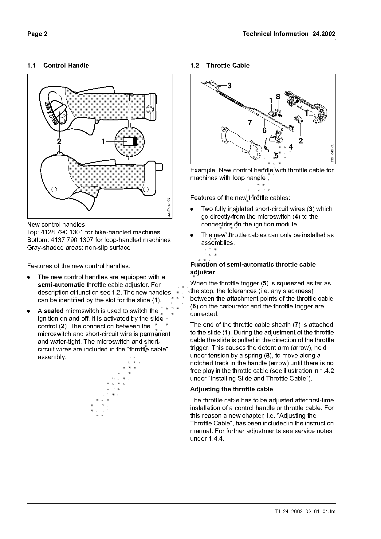
                                                                    Example: New control handle with throttle cable for
                                                                    machines with loop handle

                                                                    Features of the new throttle cables:
                                                      393TI042 KN

                                                                    .     Two fully insulated short-circuit wires (3) which
                                                                          go directly from the microswitch (4) to the
New control handles
Top: 4128 790 1301 for bike-handled machines                        .
                                                                          connectors on the ignition module.
                                                                          The new throttle cables can only be installed as
Bottom: 4137 790 1307 for loop-handled machines                           assemblies.
Gray-shaded areas: non-slip surface

                                                                    Function of semi-automatic throttle cable

Features of the new control handles:
                                                                    adjuster
.     The new control handles are equipped with a
      semi-automatic throttle cable adjuster. For                   When the throttle trigger (5) is squeezed as far as
      description of function see 1.2. The new handles              the stop, the tolerances (i.e. any slackness)

      can be identified by the slot for the slide (1).              between the attachment points of the throttle cable

                                                                    (6) on the carburetor and the throttle trigger are
.     A sealed microswitch is used to switch the                    corrected.
      ignition on and off. It is activated by the slide
      control (2). The connection between the                       The end of the throttle cable sheath (7) is attached

      microswitch and short-circuit wire is permanent               to the slide (1). During the adjustment of the throttle
      and water-tight. The microswitch and short-                   cable the slide is pulled in the direction of the throttle
      circuit wires are included in the "throttle cable"            trigger. This causes the detent arm (arrow), held

      assembly.                                                     under tension by a spring (8), to move along a
                                                                    notched track in the handle (arrow) until there is no
                                                                    free play in the throttle cable (see illustration in 1.4.2

                                                                    under "Installing Slide and Throttle Cable").
                                                                    Adjusting the throttle cable

                                                                    The throttle cable has to be adjusted after first-time
                                                                    installation of a control handle or throttle cable. For
                                                                    this reason a new chapter, i.e. "Adjusting the
                                                                    Throttle Cable", has been included in the instruction
                                                                    manual. For further adjustments see service notes
                                                                    under 1.4.4.

                                                                                                         TI_24_2002_02_01_01.fm
Page 3 of 10
Text of page 3 — search, copy, screen readers
Technical Information 24.2002                                                              Page 3

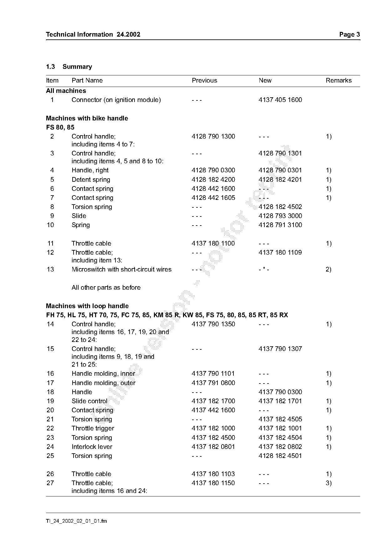
1.3    Summary

Item     Part Name                              Previous            New               Remarks
All machines
 1      Connector (on ignition module)          ---                 4137 405 1600

Machines with bike handle
FS 80, 85
 2      Control handle;                         4128 790 1300       ---               1)
        including items 4 to 7:
 3      Control handle;                         ---                 4128 790 1301

        including items 4, 5 and 8 to 10:
 4      Handle, right                           4128 790 0300       4128 790 0301     1)
 5      Detent spring                           4128 182 4200       4128 182 4201     1)

 6      Contact spring                          4128 442 1600       ---               1)
 7      Contact spring                          4128 442 1605       ---               1)
 8      Torsion spring                          ---                 4128 182 4502

 9      Slide                                   ---                 4128 793 3000
10      Spring                                  ---                 4128 791 3100
11       Throttle cable                         4137 180 1100       ---               1)
12       Throttle cable;                        ---                 4137 180 1109
         including item 13:
13       Microswitch with short-circuit wires   ---                 -*-               2)

         All other parts as before

Machines with loop handle

FH 75, HL 75, HT 70, 75, FC 75, 85, KM 85 R, KW 85, FS 75, 80, 85, 85 RT, 85 RX
14      Control handle;                        4137 790 1350          ---             1)
        including items 16, 17, 19, 20 and

        22 to 24:
15      Control handle;                        ---                    4137 790 1307

        including items 9, 18, 19 and
        21 to 25:
16      Handle molding, inner                  4137 790 1101          ---             1)

17      Handle molding, outer                  4137 791 0800          ---             1)
18      Handle                                 ---                    4137 790 0300
19      Slide control                          4137 182 1700          4137 182 1701   1)

20      Contact spring                         4137 442 1600          ---             1)
21      Torsion spring                         ---                    4137 182 4505
22      Throttle trigger                       4137 182 1000          4137 182 1001   1)
23      Torsion spring                         4137 182 4500          4137 182 4504   1)
24      Interlock lever                        4137 182 0801          4137 182 0802   1)
25      Torsion spring                         ---                    4128 182 4501

26       Throttle cable                         4137 180 1103       ---               1)
27       Throttle cable;                        4137 180 1150       ---               3)
         including items 16 and 24:

TI_24_2002_02_01_01.fm
Page 4 of 10
Text of page 4 — search, copy, screen readers
Page 4                                                                                     Technical Information 24.2002

Item      Part Name                                           Previous                  New                      Remarks
28        Throttle cable;                                         ---                   4137 180 1107
          including item 29:
29        Microswitch with short-circuit wires                    ---                   -*-                      2)

          All other parts as before

Modification to be introduced
USA production FS 80                       from serial number 2 55 972 256
                 FS 85                     from serial number 2 55 809 184

                 HT 75                     from serial number 2 55 809 912

                 KM 85 R                   since start of production
                 Other models              in progress
Remarks

1) Previous version of part remains available as spare for older machines
2) Part is not available as a separate item

3) Previous version of part remains available from factory up to about 2009

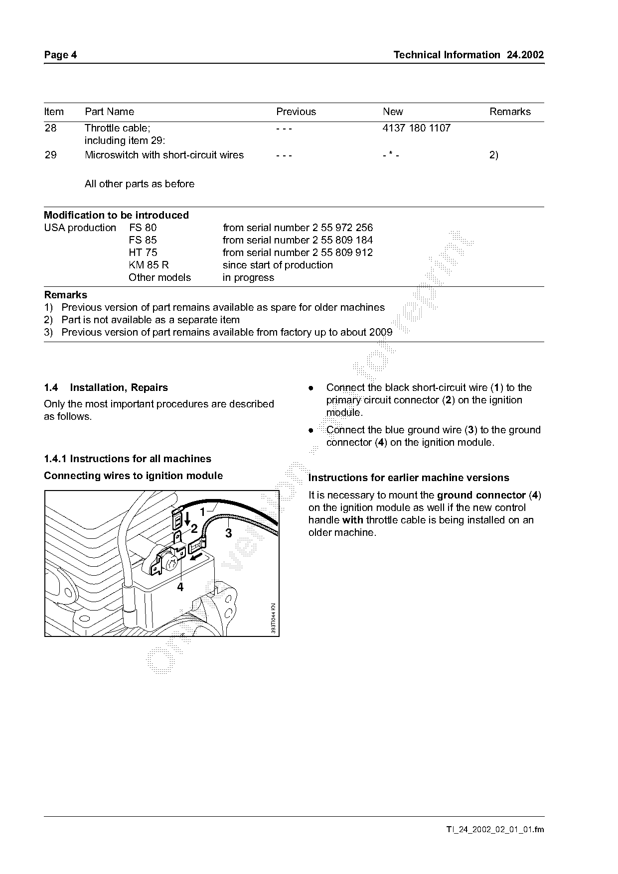
1.4    Installation, Repairs                                            .   Connect the black short-circuit wire (1) to the
                                                                            primary circuit connector (2) on the ignition
Only the most important procedures are described
as follows.                                                                 module.

                                                                        .   Connect the blue ground wire (3) to the ground
                                                                            connector (4) on the ignition module.
1.4.1 Instructions for all machines

Connecting wires to ignition module                                     Instructions for earlier machine versions

                                                                        It is necessary to mount the ground connector (4)
                                       1                                on the ignition module as well if the new control
                                                                        handle with throttle cable is being installed on an
                                   2       3                            older machine.


                                                    393TI044 KN

                                                                                                       TI_24_2002_02_01_01.fm
Page 5 of 10
Text of page 5 — search, copy, screen readers
Technical Information 24.2002                                                                                          Page 5

Adjusting the tensioner                                                Installing slide and throttle cable
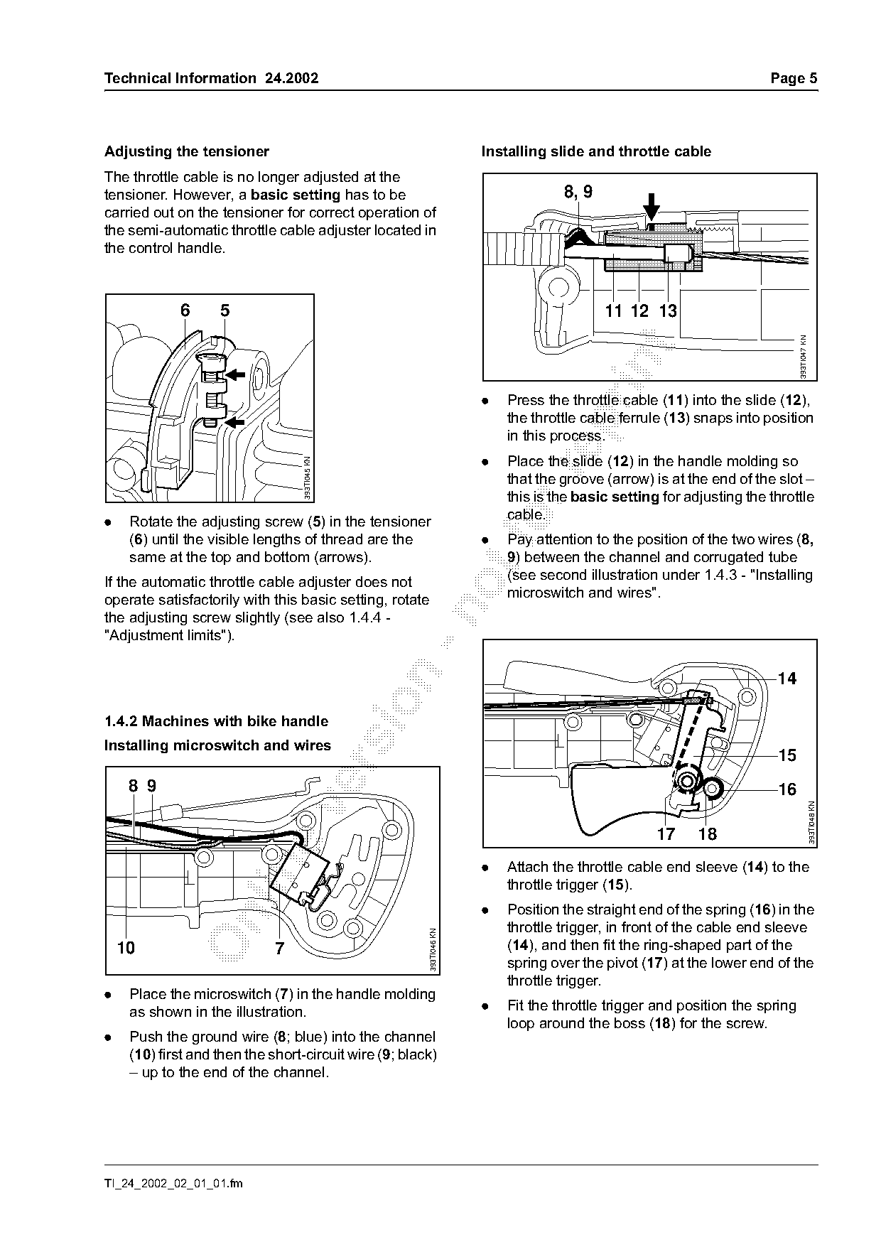
The throttle cable is no longer adjusted at the
tensioner. However, a basic setting has to be                                       8, 9
carried out on the tensioner for correct operation of
the semi-automatic throttle cable adjuster located in
the control handle.

             6      5                                                                      11 12 13

                                                                                                                              393TI047 KN
                                                                       .   Press the throttle cable (11) into the slide (12),
                                                                           the throttle cable ferrule (13) snaps into position

                                                                           in this process.
                                                                       .   Place the slide (12) in the handle molding so
                                   393TI045 KN

                                                                           that the groove (arrow) is at the end of the slot –
                                                                           this is the basic setting for adjusting the throttle
                                                                           cable.
.    Rotate the adjusting screw (5) in the tensioner
     (6) until the visible lengths of thread are the                   .
                                                                           Pay attention to the position of the two wires (8,
     same at the top and bottom (arrows).                                  9) between the channel and corrugated tube
If the automatic throttle cable adjuster does not                          (see second illustration under 1.4.3 - "Installing
operate satisfactorily with this basic setting, rotate                     microswitch and wires".

the adjusting screw slightly (see also 1.4.4 -
"Adjustment limits").


1.4.2 Machines with bike handle
Installing microswitch and wires
                                                                                                                        15

     8 9                                                                                                                16

                                                                                                                                            393TI048 KN

                                                                                                    17     18
                                                                       .   Attach the throttle cable end sleeve (14) to the

                                                                           throttle trigger (15).
                                                                       .   Position the straight end of the spring (16) in the

                                                                           throttle trigger, in front of the cable end sleeve
                                                         393TI046 KN

    10                        7                                            (14), and then fit the ring-shaped part of the
                                                                           spring over the pivot (17) at the lower end of the
                                                                           throttle trigger.
.    Place the microswitch (7) in the handle molding
     as shown in the illustration.                                     .   Fit the throttle trigger and position the spring
                                                                           loop around the boss (18) for the screw.
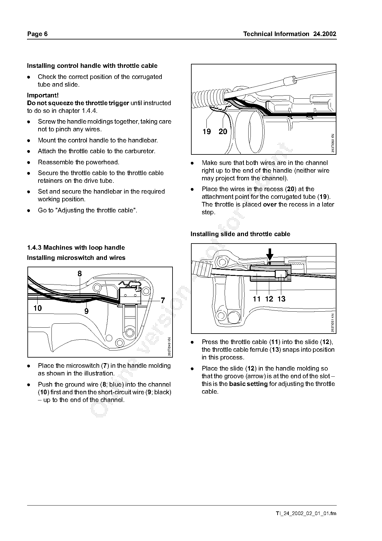
.    Push the ground wire (8; blue) into the channel
     (10) first and then the short-circuit wire (9; black)
     – up to the end of the channel.

TI_24_2002_02_01_01.fm
Page 6 of 10
Text of page 6 — search, copy, screen readers
Page 6                                                                                     Technical Information 24.2002

Installing control handle with throttle cable
.    Check the correct position of the corrugated
     tube and slide.
Important!
Do not squeeze the throttle trigger until instructed
to do so in chapter 1.4.4.
.    Screw the handle moldings together, taking care
     not to pinch any wires.                                               19    20

                                                                                                                             393TI050 KN
.    Mount the control handle to the handlebar.
.    Attach the throttle cable to the carburetor.

.    Reassemble the powerhead.                                         .   Make sure that both wires are in the channel
.    Secure the throttle cable to the throttle cable                       right up to the end of the handle (neither wire
     retainers on the drive tube.                                          may project from the channel).

.    Set and secure the handlebar in the required                      .   Place the wires in the recess (20) at the
     working position.                                                     attachment point for the corrugated tube (19).
                                                                           The throttle is placed over the recess in a later

.    Go to "Adjusting the throttle cable".                                 step.

                                                                       Installing slide and throttle cable

1.4.3 Machines with loop handle

Installing microswitch and wires


                                                     7                                        11 12 13

    10                  9

                                                                                                                             393TI051 KN
                                                         393TI049 KN

                                                                       .   Press the throttle cable (11) into the slide (12),
                                                                           the throttle cable ferrule (13) snaps into position

                                                                           in this process.
.    Place the microswitch (7) in the handle molding                   .   Place the slide (12) in the handle molding so
     as shown in the illustration.                                         that the groove (arrow) is at the end of the slot –

.    Push the ground wire (8; blue) into the channel                       this is the basic setting for adjusting the throttle
     (10) first and then the short-circuit wire (9; black)                 cable.

     – up to the end of the channel.

                                                                                                        TI_24_2002_02_01_01.fm
Page 7 of 10
Text of page 7 — search, copy, screen readers
Technical Information 24.2002                                                                                       Page 7

Installing the throttle trigger                                       1.4.4 Adjusting the throttle cable (all models)
                                                                      Important!
                                                                      Adjust the throttle cable only when the machine is
                                                                      completely and securely assembled – the handlebar
                                                                      and control handle must be in the normal operating
                                                   14                 position.
                         16
                                                   15                 This adjustment procedure removes free play from
                                                                      the throttle cable.
                                                                      Correct adjustment of the throttle cable is necessary
                                                                      for correct operation of the machine at full throttle,

                                                        393TI052 KN
                                                                      starting throttle and idling. It may therefore be

                                  17 18

                                                                      necessary to readjust the carburetor after adjusting
                                                                      the throttle cable.
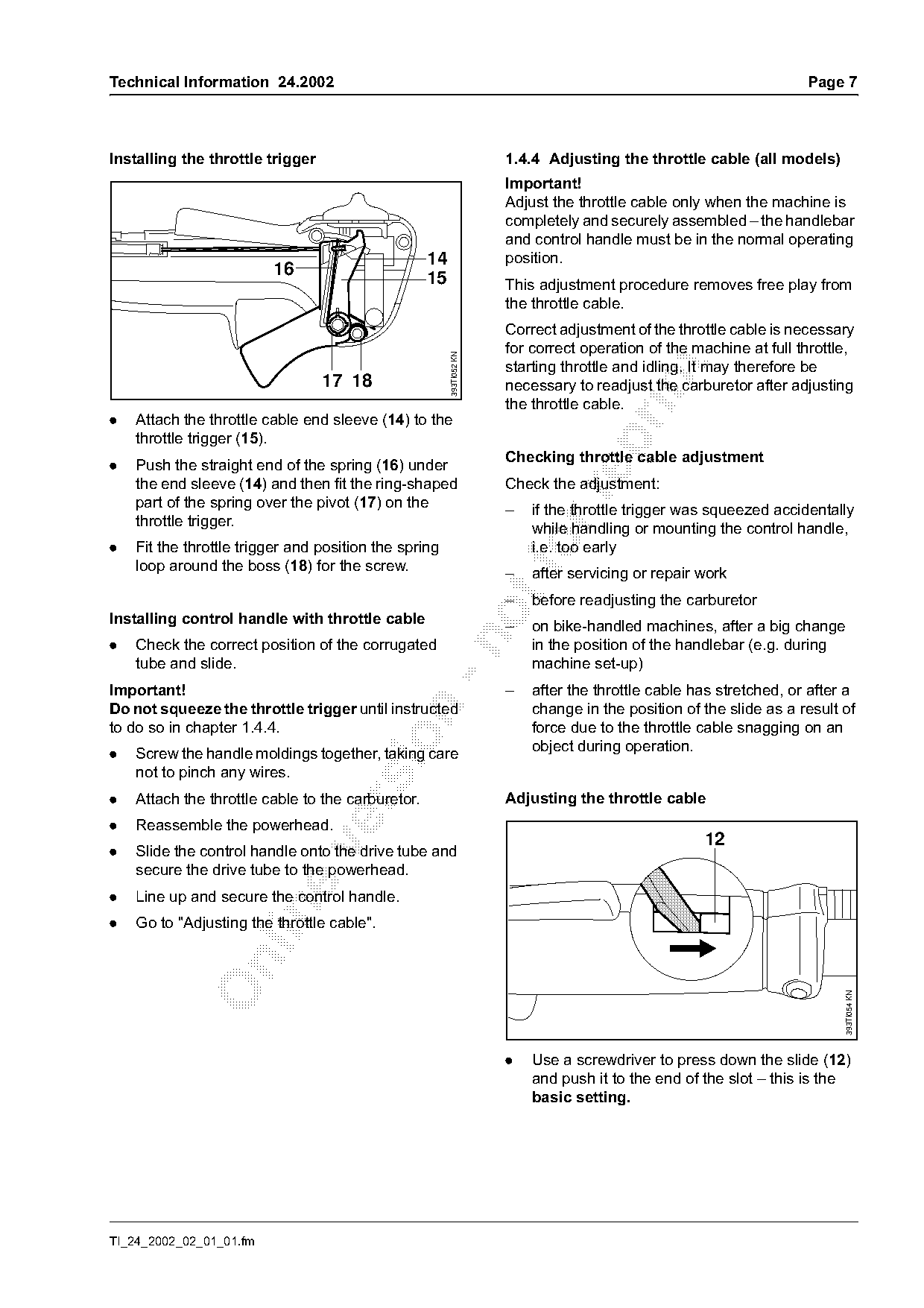
.   Attach the throttle cable end sleeve (14) to the
    throttle trigger (15).

                                                                      Checking throttle cable adjustment
.   Push the straight end of the spring (16) under
    the end sleeve (14) and then fit the ring-shaped                  Check the adjustment:

    part of the spring over the pivot (17) on the                     –   if the throttle trigger was squeezed accidentally
    throttle trigger.                                                     while handling or mounting the control handle,
.   Fit the throttle trigger and position the spring
    loop around the boss (18) for the screw.                          –
                                                                          i.e. too early
                                                                          after servicing or repair work
                                                                      –   before readjusting the carburetor
Installing control handle with throttle cable                         –   on bike-handled machines, after a big change

.   Check the correct position of the corrugated                          in the position of the handlebar (e.g. during
    tube and slide.                                                       machine set-up)
Important!                                                            –   after the throttle cable has stretched, or after a
Do not squeeze the throttle trigger until instructed                      change in the position of the slide as a result of

to do so in chapter 1.4.4.                                                force due to the throttle cable snagging on an

                                                                          object during operation.
.   Screw the handle moldings together, taking care
    not to pinch any wires.
.   Attach the throttle cable to the carburetor.                      Adjusting the throttle cable

.   Reassemble the powerhead.
                                                                                                    12

.   Slide the control handle onto the drive tube and
    secure the drive tube to the powerhead.
.   Line up and secure the control handle.

.   Go to "Adjusting the throttle cable".

                                                                                                                          393TI054 KN

                                                                      .   Use a screwdriver to press down the slide (12)
                                                                          and push it to the end of the slot – this is the
                                                                          basic setting.

TI_24_2002_02_01_01.fm
Page 8 of 10
Text of page 8 — search, copy, screen readers
Page 8                                                                                Technical Information 24.2002

                                                                   2.    Rewind Starter
                          21              12
                                                                                                    2

                                                                                                               1
                                                                                                               4

                                                     393TI053 KN
                                                                                                               3
                  15

                                                                                                                        393TI056 KN
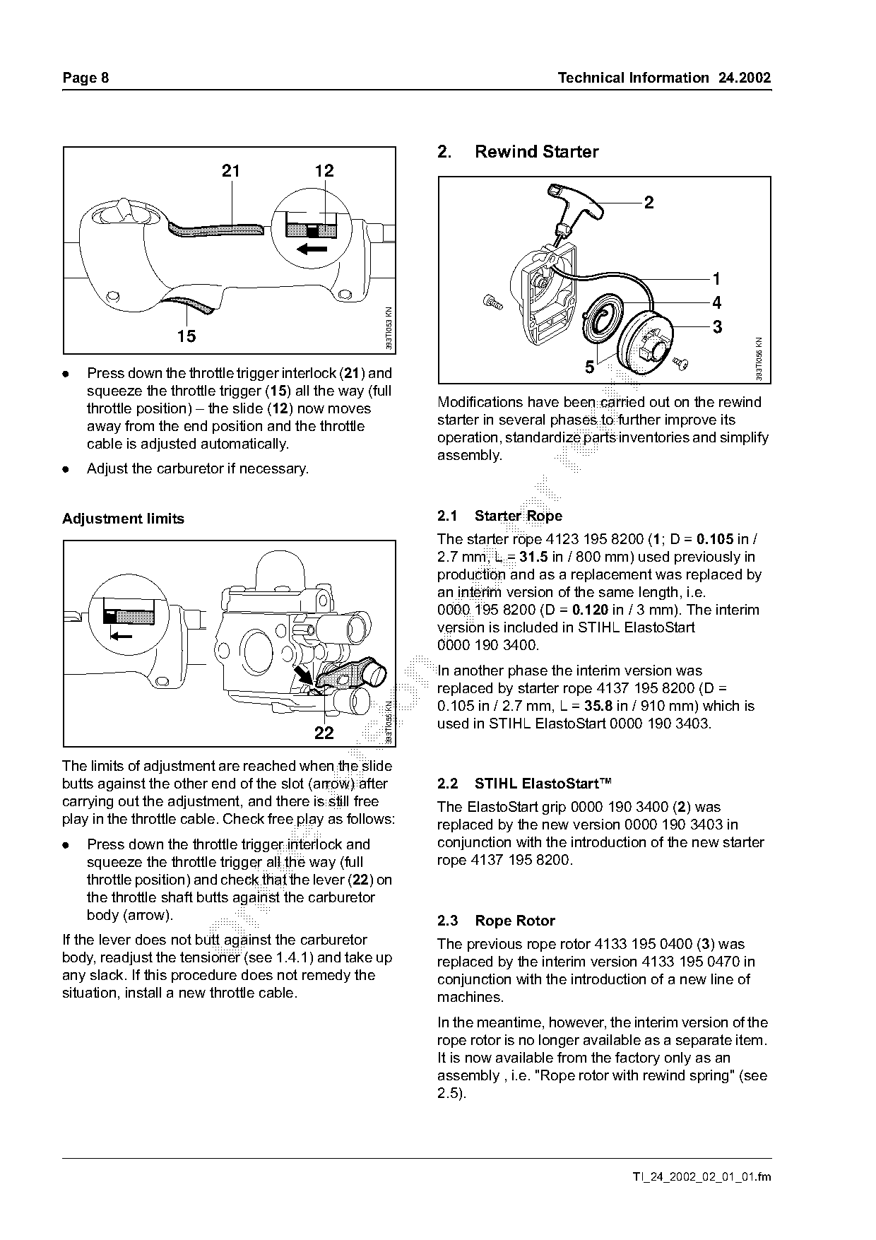
.   Press down the throttle trigger interlock (21) and                                    5
    squeeze the throttle trigger (15) all the way (full
    throttle position) – the slide (12) now moves                  Modifications have been carried out on the rewind

    away from the end position and the throttle                    starter in several phases to further improve its
    cable is adjusted automatically.                               operation, standardize parts inventories and simplify
                                                                   assembly.
.   Adjust the carburetor if necessary.

Adjustment limits                                                  2.1     fo
                                                                         Starter Rope
                                                                   The starter rope 4123 195 8200 (1; D = 0.105 in /
                                                                   2.7 mm, L = 31.5 in / 800 mm) used previously in
                                                                   production and as a replacement was replaced by
                                                                   an interim version of the same length, i.e.

                                                                   0000 195 8200 (D = 0.120 in / 3 mm). The interim
                                                                   version is included in STIHL ElastoStart
                                                                   0000 190 3400.
                                                                   In another phase the interim version was

                                                                   replaced by starter rope 4137 195 8200 (D =

                                                                   0.105 in / 2.7 mm, L = 35.8 in / 910 mm) which is
                                                     393TI055 KN

                                                                   used in STIHL ElastoStart 0000 190 3403.
                                          22

The limits of adjustment are reached when the slide
butts against the other end of the slot (arrow) after              2.2   STIHL ElastoStart™
carrying out the adjustment, and there is still free

                                                                   The ElastoStart grip 0000 190 3400 (2) was
play in the throttle cable. Check free play as follows:            replaced by the new version 0000 190 3403 in
.   Press down the throttle trigger interlock and                  conjunction with the introduction of the new starter
    squeeze the throttle trigger all the way (full                 rope 4137 195 8200.

    throttle position) and check that the lever (22) on
    the throttle shaft butts against the carburetor

    body (arrow).                                                  2.3   Rope Rotor
If the lever does not butt against the carburetor                  The previous rope rotor 4133 195 0400 (3) was
body, readjust the tensioner (see 1.4.1) and take up               replaced by the interim version 4133 195 0470 in
any slack. If this procedure does not remedy the                   conjunction with the introduction of a new line of
situation, install a new throttle cable.                           machines.
                                                                   In the meantime, however, the interim version of the
                                                                   rope rotor is no longer available as a separate item.
                                                                   It is now available from the factory only as an
                                                                   assembly , i.e. "Rope rotor with rewind spring" (see
                                                                   2.5).

                                                                                                  TI_24_2002_02_01_01.fm
Page 9 of 10
Text of page 9 — search, copy, screen readers
Technical Information 24.2002                                                                             Page 9

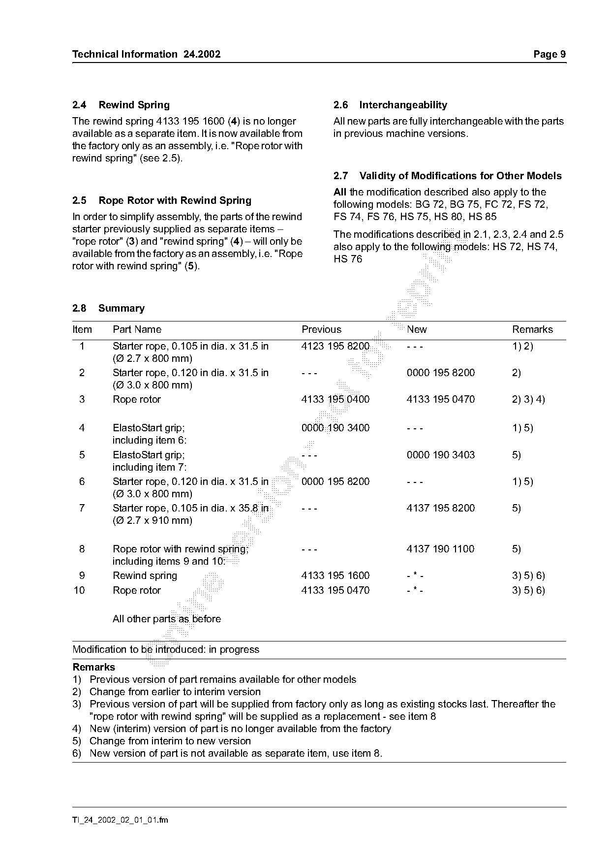
2.4    Rewind Spring                                        2.6   Interchangeability
The rewind spring 4133 195 1600 (4) is no longer            All new parts are fully interchangeable with the parts
available as a separate item. It is now available from      in previous machine versions.
the factory only as an assembly, i.e. "Rope rotor with
rewind spring" (see 2.5).
                                                            2.7   Validity of Modifications for Other Models
                                                            All the modification described also apply to the
2.5    Rope Rotor with Rewind Spring                        following models: BG 72, BG 75, FC 72, FS 72,
In order to simplify assembly, the parts of the rewind      FS 74, FS 76, HS 75, HS 80, HS 85
starter previously supplied as separate items –
                                                            The modifications described in 2.1, 2.3, 2.4 and 2.5
"rope rotor" (3) and "rewind spring" (4) – will only be

                                                            also apply to the following models: HS 72, HS 74,

available from the factory as an assembly, i.e. "Rope
                                                            HS 76
rotor with rewind spring" (5).

2.8    Summary

Item     Part Name                                    Previous               New                     Remarks
 1       Starter rope, 0.105 in dia. x 31.5 in        4123 195 8200          ---                     1) 2)
         (Ø 2.7 x 800 mm)
 2       Starter rope, 0.120 in dia. x 31.5 in        ---
                                                             fo              0000 195 8200           2)
         (Ø 3.0 x 800 mm)
 3       Rope rotor                                   4133 195 0400          4133 195 0470           2) 3) 4)

 4       ElastoStart grip;                            0000 190 3400          ---                     1) 5)
         including item 6:
 5       ElastoStart grip;                            ---                    0000 190 3403           5)
         including item 7:

 6       Starter rope, 0.120 in dia. x 31.5 in        0000 195 8200          ---                     1) 5)

         (Ø 3.0 x 800 mm)
 7       Starter rope, 0.105 in dia. x 35.8 in        ---                    4137 195 8200           5)
         (Ø 2.7 x 910 mm)

 8       Rope rotor with rewind spring;               ---                    4137 190 1100           5)

         including items 9 and 10:
 9       Rewind spring                                4133 195 1600          -*-                     3) 5) 6)
10       Rope rotor                                   4133 195 0470          -*-                     3) 5) 6)

         All other parts as before

Modification to be introduced: in progress
Remarks
1) Previous version of part remains available for other models
2) Change from earlier to interim version
3) Previous version of part will be supplied from factory only as long as existing stocks last. Thereafter the
   "rope rotor with rewind spring" will be supplied as a replacement - see item 8
4) New (interim) version of part is no longer available from the factory
5) Change from interim to new version
6) New version of part is not available as separate item, use item 8.

TI_24_2002_02_01_01.fm
Page 10 of 10
Text of page 10 — search, copy, screen readers
Page 10                                                           Technical Information 24.2002

Last Technical Information on models:            FC 75, FC 85                            32.2001
                                                 FH 75                                   42.2001
                                                 FS 75, FS 80, FS 85                     32.2001
                                                 FS 85 RX                                03.2002
                                                 HL 75                                   42.2001
                                                 HT 70, HT 75                            38.2002
                                                 KM 85 R                                 14.2002
                                                 KW 85                                   32.2001

© 2002 Andreas Stihl AG & Co.                    Technical Documentation
  Waiblingen                                     D1/MTK-na                                  7811

                                                                            TI_24_2002_02_01_01.fm
Most of these PDFs embed fonts with a shifted character map, so the text above was recovered rather than copied — read it as a faithful but imperfect transcription, and treat the page image above each block as the authority where the two disagree — the figures exist only there, because they are vector drawings that text extraction cannot keep.