Technical Information · issue 28 of 2002
Decompression Valve; Cylinder with Piston; Shroud
Model MS 440 Chainsaws – Series 1128
IssueTI 28/2002
Engine family 1128
Part changes (2)
| Was | Becomes | What the bulletin says |
|---|---|---|
| 1128 020 1226 | 1128 020 1227 | 175TI002 KN The previous cylinder with piston 1128 020 1226 will be replaced by the version 1128 020 1227. |
| 1128 141 2200 | 1128 141 2203 | Manifold The previous manifolds 1128 141 2200 and 1128 141 2202 will be replaced by manifold 1128 141 2203 to further optimize resistance to high and low temperatures. |
Full text
Page 1 of 3
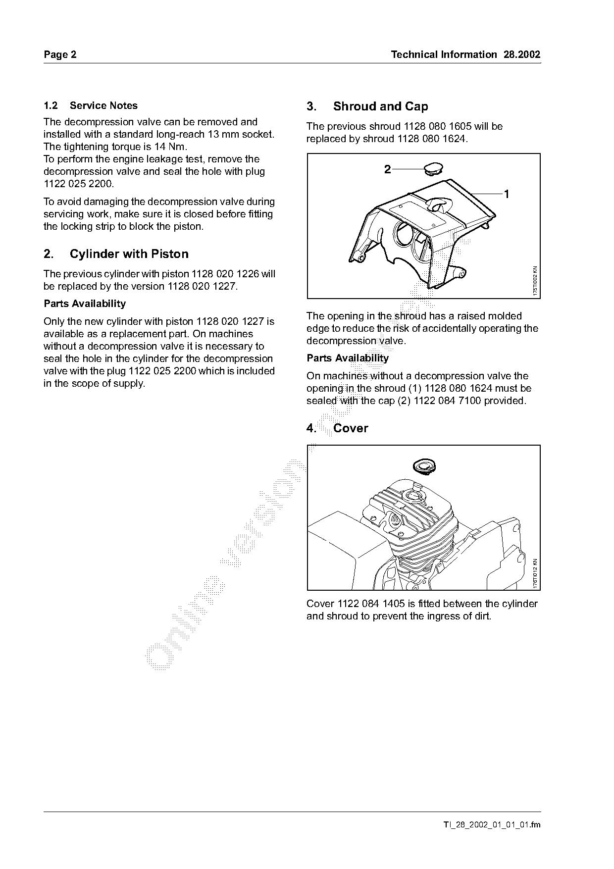
Text of page 1 — search, copy, screen readers
Technical Information

                                                                                              28.2002
Model MS 440 Chainsaws – Series 1128

Contents
1.    Decompression Valve
2.    Cylinder with Piston

3.    Shroud and Cap

4.    Cover
5.    Manifold
6.    Summary

1.     Decompression Valve
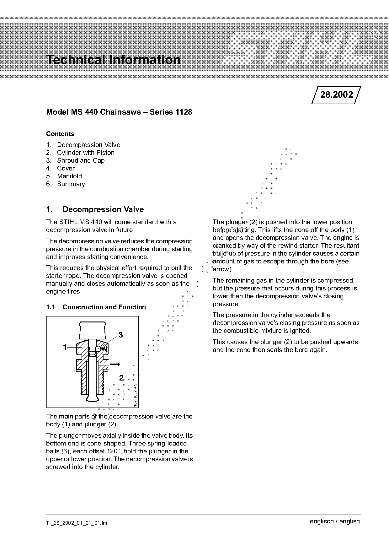
The STIHL MS 440 will come standard with a              The plunger (2) is pushed into the lower position
decompression valve in future.
The decompression valve reduces the compression
                                                        before starting. This lifts the cone off the body (1)
                                                        and opens the decompression valve. The engine is
pressure in the combustion chamber during starting      cranked by way of the rewind starter. The resultant
and improves starting convenience.                      build-up of pressure in the cylinder causes a certain
                                                        amount of gas to escape through the bore (see
This reduces the physical effort required to pull the   arrow).

starter rope. The decompression valve is opened
                                                        The remaining gas in the cylinder is compressed,
manually and closes automatically as soon as the
                                                        but the pressure that occurs during this process is
engine fires.
                                                        lower than the decompression valve’s closing

                                                        pressure.
1.1    Construction and Function

                                                        The pressure in the cylinder exceeds the
                                                        decompression valve’s closing pressure as soon as
                                                        the combustible mixture is ignited.
                          3

                                                        This causes the plunger (2) to be pushed upwards
       1                                                and the cone then seals the bore again.

                          2
                               137TI007 KN

The main parts of the decompression valve are the
body (1) and plunger (2).
The plunger moves axially inside the valve body. Its
bottom end is cone-shaped. Three spring-loaded
balls (3), each offset 120°, hold the plunger in the
upper or lower position. The decompression valve is
screwed into the cylinder.

TI_28_2002_01_01_01.fm                                                                     englisch / english
Page 2 of 3
Text of page 2 — search, copy, screen readers
Page 2                                                                       Technical Information 28.2002

1.2   Service Notes                                     3.    Shroud and Cap
The decompression valve can be removed and              The previous shroud 1128 080 1605 will be
installed with a standard long-reach 13 mm socket.      replaced by shroud 1128 080 1624.
The tightening torque is 14 Nm.
To perform the engine leakage test, remove the
decompression valve and seal the hole with plug                          2
1122 025 2200.
                                                                                                     1
To avoid damaging the decompression valve during
servicing work, make sure it is closed before fitting
the locking strip to block the piston.

2.    Cylinder with Piston

                                                                                                           175TI002 KN
The previous cylinder with piston 1128 020 1226 will
be replaced by the version 1128 020 1227.

Parts Availability
                                                        The opening in the shroud has a raised molded
Only the new cylinder with piston 1128 020 1227 is
                                                        edge to reduce the risk of accidentally operating the

available as a replacement part. On machines
                                                        decompression valve.
without a decompression valve it is necessary to
seal the hole in the cylinder for the decompression     Parts Availability
valve with the plug 1122 025 2200 which is included
in the scope of supply.
                                                        On machines without a decompression valve the
                                                        opening in the shroud (1) 1128 080 1624 must be
                                                        sealed with the cap (2) 1122 084 7100 provided.

                                                        4.    Cover

                                                                                                           176TI012 KN

                                                        Cover 1122 084 1405 is fitted between the cylinder

                                                        and shroud to prevent the ingress of dirt.

                                                                                       TI_28_2002_01_01_01.fm
Page 3 of 3
Text of page 3 — search, copy, screen readers
Technical Information 28.2002                                                                         Page 3

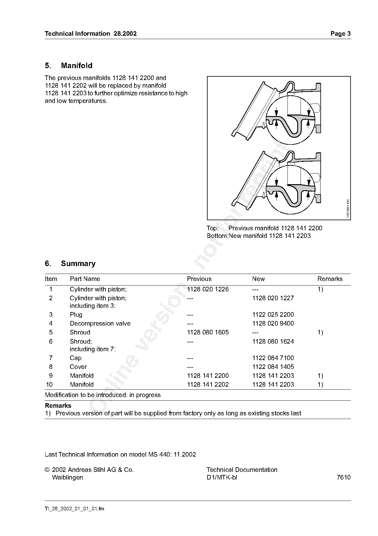
5.     Manifold
The previous manifolds 1128 141 2200 and
1128 141 2202 will be replaced by manifold
1128 141 2203 to further optimize resistance to high
and low temperatures.

                                                                                                           175TI001 KN
                                                           Top:   Previous manifold 1128 141 2200
                                                           Bottom:New manifold 1128 141 2203

6.     Summary

Item     Part Name                                  Previous                New                  Remarks
 1       Cylinder with piston;                      1128 020 1226           ---                  1)

 2       Cylinder with piston;                      ---                     1128 020 1227

         including item 3:
 3       Plug                                       ---                     1122 025 2200
 4       Decompression valve                        ---                     1128 020 9400

 5       Shroud                                     1128 080 1605           ---                  1)
 6       Shroud;                                    ---                     1128 080 1624

         including item 7:
 7       Cap                                        ---                     1122 084 7100
 8       Cover                                      ---                     1122 084 1405

 9       Manifold                                   1128 141 2200           1128 141 2203        1)
10       Manifold                                   1128 141 2202           1128 141 2203        1)
Modification to be introduced: in progress

Remarks
1) Previous version of part will be supplied from factory only as long as existing stocks last

Last Technical Information on model MS 440: 11.2002

© 2002 Andreas Stihl AG & Co.                              Technical Documentation
  Waiblingen                                               D1/MTK-bl                                   7610

TI_28_2002_01_01_01.fm
Most of these PDFs embed fonts with a shifted character map, so the text above was recovered rather than copied — read it as a faithful but imperfect transcription, and treat the page image above each block as the authority where the two disagree — the figures exist only there, because they are vector drawings that text extraction cannot keep.