Technical Information · issue 29 of 2002
Control Handle, Throttle Cable, Cable Guide; Carburetor; Gearhead
Model FS 550 Clearing Saws – Series 4116
IssueTI 29/2002
Part changes (1)
| Was | Becomes | What the bulletin says |
|---|---|---|
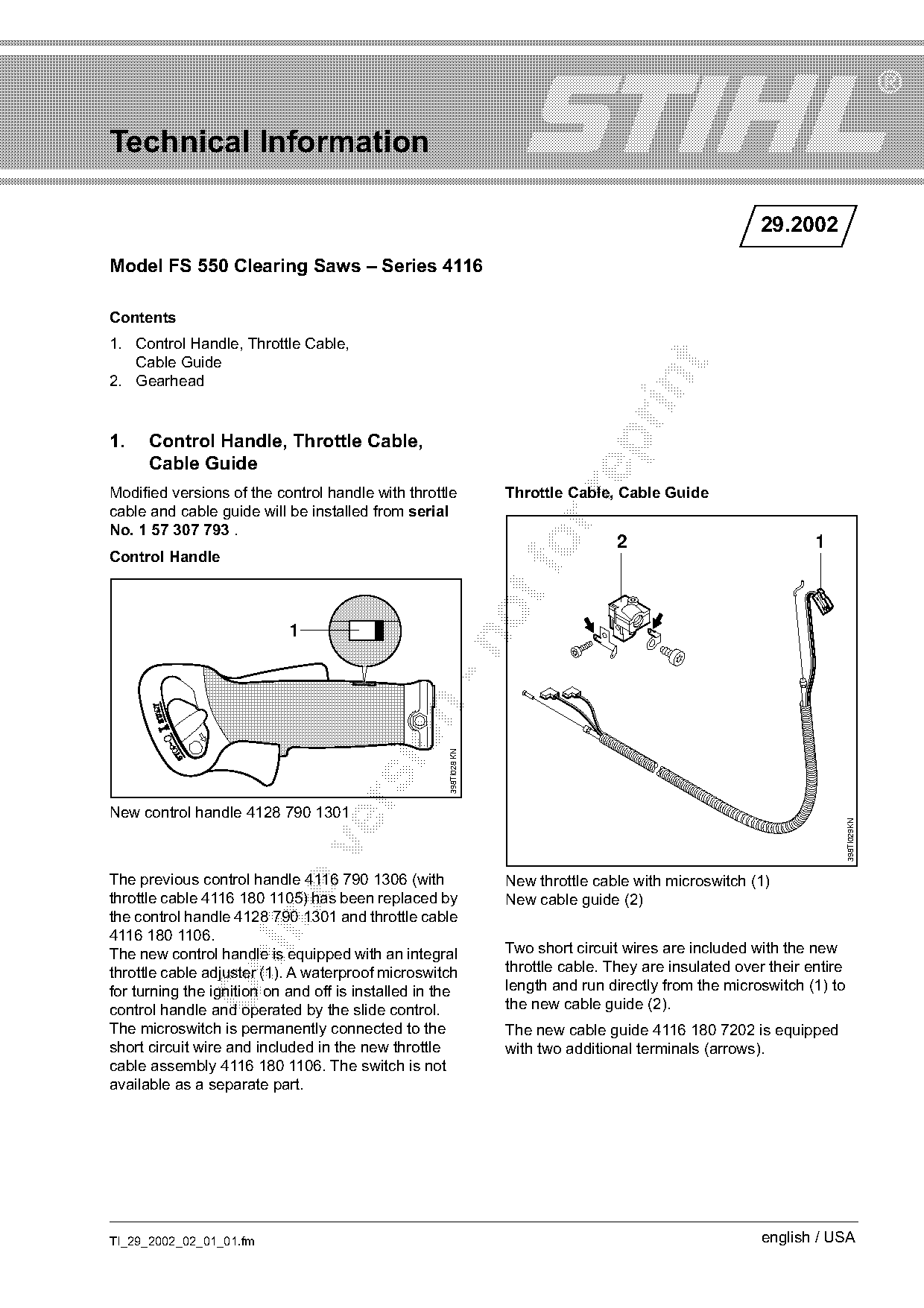
| 4116 790 1306 | 4128 790 1301 | The previous control handle 4116 790 1306 (with New throttle cable with microswitch (1) throttle cable 4116 180 1105) has been replaced by New cable guide (2) the control handle 4128 790 1301 and throttle cable 4116 180 1106. |
Full text
Page 1 of 4
Text of page 1 — search, copy, screen readers
Technical Information

                                                                                                          29.2002
Model FS 550 Clearing Saws – Series 4116

Contents
1. Control Handle, Throttle Cable,
   Cable Guide

2. Gearhead

1.    Control Handle, Throttle Cable,

      Cable Guide
Modified versions of the control handle with throttle              Throttle Cable, Cable Guide

cable and cable guide will be installed from serial
No. 1 57 307 793 .
Control Handle                                                      fo              2                             1

                            1
                                                     398TI028 KN

New control handle 4128 790 1301

                                                                                                                          398TI029KN

The previous control handle 4116 790 1306 (with                    New throttle cable with microswitch (1)
throttle cable 4116 180 1105) has been replaced by                 New cable guide (2)

the control handle 4128 790 1301 and throttle cable
4116 180 1106.
The new control handle is equipped with an integral                Two short circuit wires are included with the new

throttle cable adjuster (1). A waterproof microswitch              throttle cable. They are insulated over their entire
for turning the ignition on and off is installed in the            length and run directly from the microswitch (1) to
control handle and operated by the slide control.                  the new cable guide (2).
The microswitch is permanently connected to the                    The new cable guide 4116 180 7202 is equipped
short circuit wire and included in the new throttle                with two additional terminals (arrows).
cable assembly 4116 180 1106. The switch is not
available as a separate part.

TI_29_2002_02_01_01.fm                                                                                    english / USA
Page 2 of 4
Text of page 2 — search, copy, screen readers
Page 2                                                                        Technical Information 29.2002

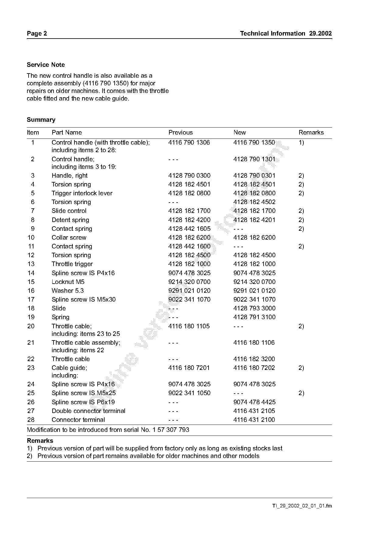
Service Note
The new control handle is also available as a
complete assembly (4116 790 1350) for major
repairs on older machines. It comes with the throttle
cable fitted and the new cable guide.

Summary

Item     Part Name                                  Previous                New                    Remarks
 1       Control handle (with throttle cable);      4116 790 1306           4116 790 1350          1)

         including items 2 to 28:

 2       Control handle;                            ---                     4128 790 1301
         including items 3 to 19:
 3       Handle, right                              4128 790 0300           4128 790 0301          2)

 4       Torsion spring                             4128 182 4501           4128 182 4501          2)
 5       Trigger interlock lever                    4128 182 0800           4128 182 0800          2)

 6       Torsion spring                             ---                     4128 182 4502
 7       Slide control                              4128 182 1700           4128 182 1700          2)
 8       Detent spring                              4128 182 4200           4128 182 4201          2)
 9       Contact spring                             4128 442 1605
                                                                    fo      ---                    2)
10       Collar screw                               4128 182 6200           4128 182 6200
11       Contact spring                             4128 442 1600           ---                    2)
12       Torsion spring                             4128 182 4500           4128 182 4500

13       Throttle trigger                           4128 182 1000           4128 182 1000
14       Spline screw IS P4x16                      9074 478 3025           9074 478 3025
15       Locknut M5                                 9214 320 0700           9214 320 0700

16       Washer 5.3                                 9291 021 0120           9291 021 0120
17       Spline screw IS M5x30                      9022 341 1070           9022 341 1070

18       Slide                                      ---                     4128 793 3000
19       Spring                                     ---                     4128 791 3100
20       Throttle cable;                            4116 180 1105           ---                    2)

         including: items 23 to 25
21       Throttle cable assembly;                   ---                     4116 180 1106

         including: items 22
22       Throttle cable                             ---                     4116 182 3200
23       Cable guide;                               4116 180 7201           4116 180 7202          2)

         including:
24       Spline screw IS P4x16                      9074 478 3025           9074 478 3025

25       Spline screw IS M5x25                      9022 341 1050           ---                    2)
26       Spline screw IS P6x19                      ---                     9074 478 4425
27       Double connector terminal                  ---                     4116 431 2105
28       Connector terminal                         ---                     4116 431 2100
Modification to be introduced from serial No. 1 57 307 793
Remarks
1) Previous version of part will be supplied from factory only as long as existing stocks last
2) Previous version of part remains available for older machines and other models

                                                                                          TI_29_2002_02_01_01.fm
Page 3 of 4
Text of page 3 — search, copy, screen readers
Technical Information 29.2002                                                                                             Page 3

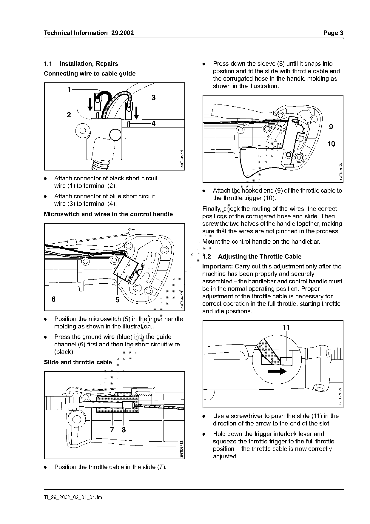
1.1     Installation, Repairs                                           .     Press down the sleeve (8) until it snaps into
Connecting wire to cable guide                                                position and fit the slide with throttle cable and
                                                                              the corrugated hose in the handle molding as
                                                                              shown in the illustration.
           1
                                            3

           2
                                             4                                                                              9


                                                          398TI035 KN

                                                                                                                                    398TI038 KN
.     Attach connector of black short circuit
      wire (1) to terminal (2).
                                                                        .     Attach the hooked end (9) of the throttle cable to
.     Attach connector of blue short circuit                                  the throttle trigger (10).

      wire (3) to terminal (4).
                                                                        Finally, check the routing of the wires, the correct
Microswitch and wires in the control handle                             positions of the corrugated hose and slide. Then
                                                                        screw the two halves of the handle together, making
                                                                        sure that the wires are not pinched in the process.
                                                                        Mount the control handle on the handlebar.

                                                                        1.2     Adjusting the Throttle Cable

                                                                        Important: Carry out this adjustment only after the
                                                                        machine has been properly and securely
                                                                        assembled – the handlebar and control handle must

                                                                        be in the normal operating position. Proper
                                                          398TI036 KN

                                                                        adjustment of the throttle cable is necessary for
    6                         5
                                                                        correct operation in the full throttle, starting throttle
                                                                        and idle positions.
.     Position the microswitch (5) in the inner handle

      molding as shown in the illustration.                                                              11
.     Press the ground wire (blue) into the guide

      channel (6) first and then the short circuit wire
      (black)
Slide and throttle cable

                                                                                                                                  398TI039 KN

                                                                        .     Use a screwdriver to push the slide (11) in the
                                                                              direction of the arrow to the end of the slot.
                            7 8                                         .     Hold down the trigger interlock lever and
                                                                              squeeze the throttle trigger to the full throttle
                                                          398TI037 KN

                                                                              position – the throttle cable is now correctly
                                                                              adjusted.
.     Position the throttle cable in the slide (7).

TI_29_2002_02_01_01.fm
Page 4 of 4
Text of page 4 — search, copy, screen readers
Page 4                                                                            Technical Information 29.2002

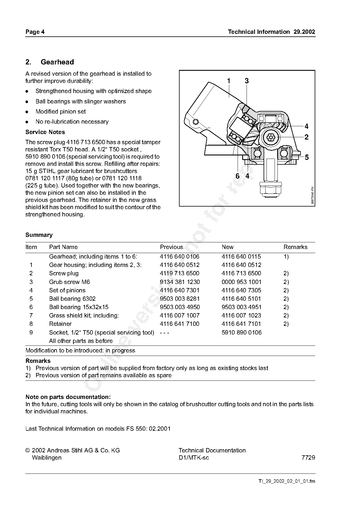
2.       Gearhead
A revised version of the gearhead is installed to
further improve durability:                                                       1      3
.       Strengthened housing with optimized shape
.       Ball bearings with slinger washers
.       Modified pinion set
.       No re-lubrication necessary
                                                                                                                  4
Service Notes
                                                                                                                  2
The screw plug 4116 713 6500 has a special tamper

resistant Torx T50 head. A 1/2“ T50 socket ,
5910 890 0106 (special servicing tool) is required to                                                             5
remove and install this screw. Refilling after repairs:
15 g STIHL gear lubricant for brushcutters

0781 120 1117 (80g tube) or 0781 120 1118                                             6 4
(225 g tube). Used together with the new bearings,

                                                                                                                      398TI040 KN
the new pinion set can also be installed in the
previous gearhead. The retainer in the new grass
shield kit has been modified to suit the contour of the
strengthened housing.                                                  fo
Summary

Item         Part Name                                   Previous               New                      Remarks

             Gearhead; including items 1 to 6:           4116 640 0106          4116 640 0115            1)
    1        Gear housing; including items 2, 3:         4116 640 0512          4116 640 0512
    2        Screw plug                                  4119 713 6500          4116 713 6500            2)

    3        Grub screw M6                               9134 381 1230          0000 953 1001            2)

    4        Set of pinions                              4116 640 7301          4116 640 7305            2)
    5        Ball bearing 6302                           9503 003 8281          4116 640 5101            2)
    6        Ball bearing 15x32x15                       9503 003 4950          9503 003 4951            2)

    7        Grass shield kit; including:                4116 007 1007          4116 007 1023            2)
    8        Retainer                                    4116 641 7100          4116 641 7101            2)

    9        Socket, 1/2“ T50 (special servicing tool)   ---                    5910 890 0106
             All other parts as before
Modification to be introduced: in progress

Remarks
1) Previous version of part will be supplied from factory only as long as existing stocks last

2) Previous version of part remains available as spare

Note on parts documentation:
In the future, cutting tools will only be shown in the catalog of brushcutter cutting tools and not in the parts lists
for individual machines.

Last Technical Information on models FS 550: 02.2001

© 2002 Andreas Stihl AG & Co. KG                               Technical Documentation
  Waiblingen                                                   D1/MTK-sc                                         7729

                                                                                               TI_29_2002_02_01_01.fm
Most of these PDFs embed fonts with a shifted character map, so the text above was recovered rather than copied — read it as a faithful but imperfect transcription, and treat the page image above each block as the authority where the two disagree — the figures exist only there, because they are vector drawings that text extraction cannot keep.