Technical Information · issue 41 of 2002
New Model FS 100 Brushcutter
Model FS tool Sound Sound power Vibration Vibration
Full text
Page 1 of 21
Text of page 1 — search, copy, screen readers
Technical Information

                                                                                              41.2002
New Model FS 100 Brushcutter – Series 4180

Contents
1.   Technical Description
2.   Specifications

3.   Cutting Tools

4.   Accessories
5.   Service Accessories
6.   Service Note

7.   Spare Parts

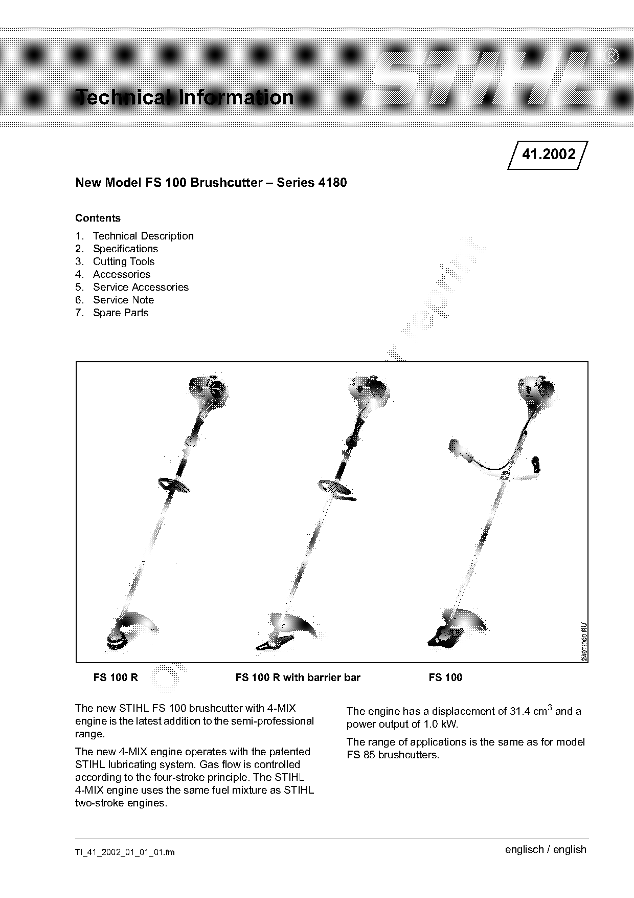
     FS 100 R                       FS 100 R with barrier bar              FS 100

The new STIHL FS 100 brushcutter with 4-MIX               The engine has a displacement of 31.4 cm3 and a
engine is the latest addition to the semi-professional    power output of 1.0 kW.
range.
                                                          The range of applications is the same as for model
The new 4-MIX engine operates with the patented           FS 85 brushcutters.
STIHL lubricating system. Gas flow is controlled
according to the four-stroke principle. The STIHL
4-MIX engine uses the same fuel mixture as STIHL
two-stroke engines.

TI_41_2002_01_01_01.fm                                                                     englisch / english
Page 2 of 21
Text of page 2 — search, copy, screen readers
Page 2                                                                              Technical Information 41.2002

1.     Technical Description                                      1.1.2 Valve Timing Gear

1.1    STIHL 4-MIX Engine
The 4-MIX engine features gas-oil lubrication.                                                            7
Compared to a conventional four-stroke engine, the
4-MIX engine has no separate oil supply in the
crankcase. Engine lubrication is effected by way the
fuel mixture of gasoline and engine oil.                                    1                             2
The benefits of this new concept are:                                                                     6
.     Familiar fuel mix                                                                                   5

.     Favorable fuel consumption

.     Operates in all positions                                                                           4
.     Reduced emissions

.     Good acceleration
.     Compact construction – attractive design                                                            3

                                                                                                                     254TI011 KN
.     Favorable power-to-weight ratio
.     Simple maintenance – service-friendly
.     More pleasant engine note – lower noise level
                                                                  .       fo
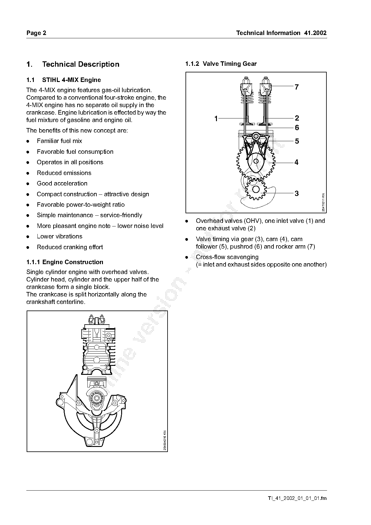
                                                                      Overhead valves (OHV), one inlet valve (1) and
                                                                      one exhaust valve (2)
.     Lower vibrations                                            .   Valve timing via gear (3), cam (4), cam
.     Reduced cranking effort                                         follower (5), pushrod (6) and rocker arm (7)
                                                                  .   Cross-flow scavenging

1.1.1 Engine Construction                                             (= inlet and exhaust sides opposite one another)
Single cylinder engine with overhead valves.
Cylinder head, cylinder and the upper half of the

crankcase form a single block.
The crankcase is split horizontally along the

crankshaft centerline.

                                                    254BA016 KN

                                                                                                TI_41_2002_01_01_01.fm
Page 3 of 21
Text of page 3 — search, copy, screen readers
Technical Information 41.2002                                                                                    Page 3

1.2     Tank Cap
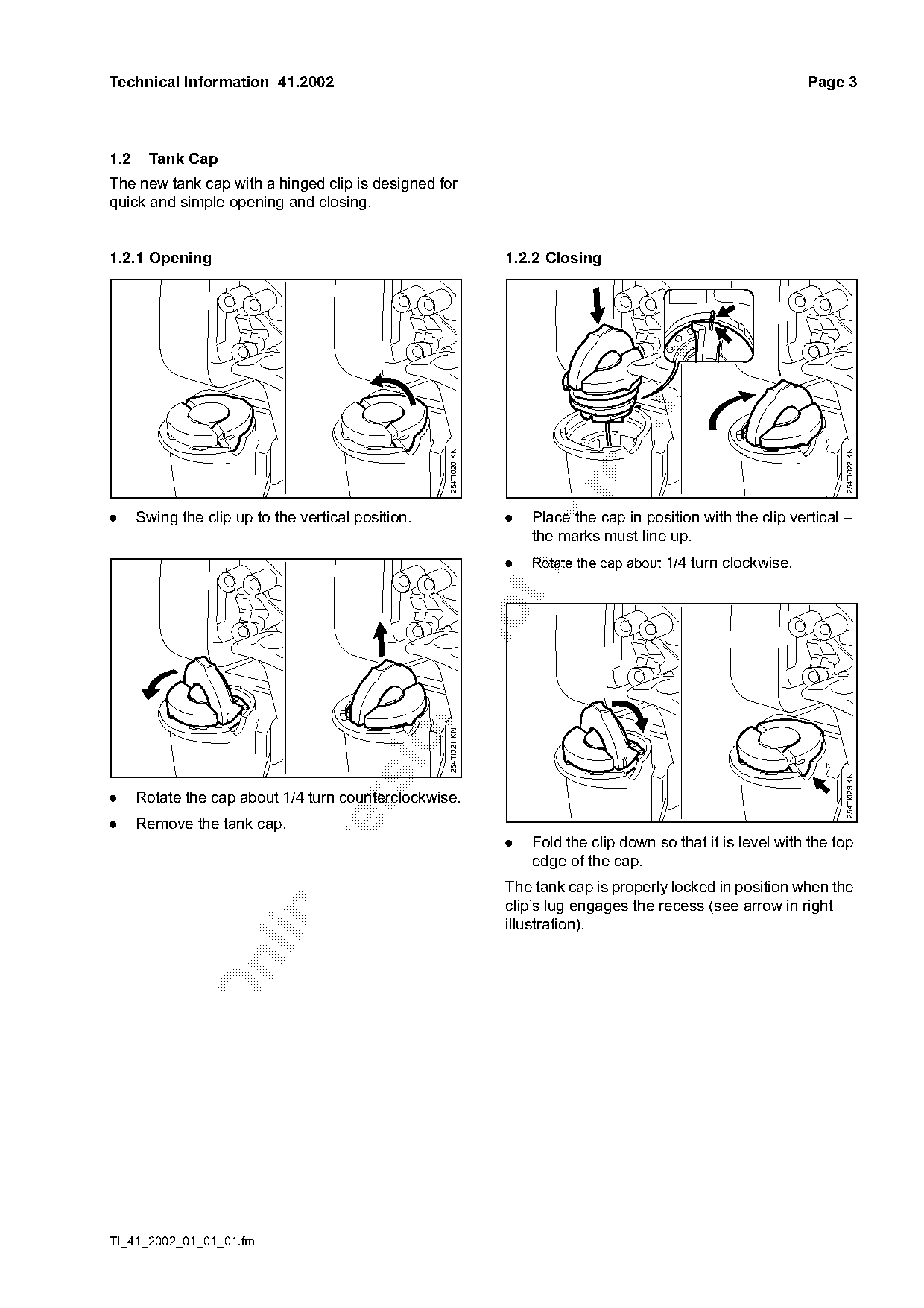
The new tank cap with a hinged clip is designed for
quick and simple opening and closing.

1.2.1 Opening                                                     1.2.2 Closing

                                                    254TI020 KN

                                                                                                                       254TI022 KN
.     Swing the clip up to the vertical position.                 .   Place the cap in position with the clip vertical –
                                                                      the marks must line up.
                                                                  .
                                                                      Rotate the cap about 1/4 turn clockwise.
                                                n   254TI021 KN

                                                                                                                       254TI023 KN
.     Rotate the cap about 1/4 turn counterclockwise.

.     Remove the tank cap.
                                                                  .   Fold the clip down so that it is level with the top

                                                                      edge of the cap.
                                                                  The tank cap is properly locked in position when the
                                                                  clip’s lug engages the recess (see arrow in right

                                                                  illustration).

TI_41_2002_01_01_01.fm
Page 4 of 21
Text of page 4 — search, copy, screen readers
Page 4                                                                                Technical Information 41.2002

1.3   Engine Lubrication
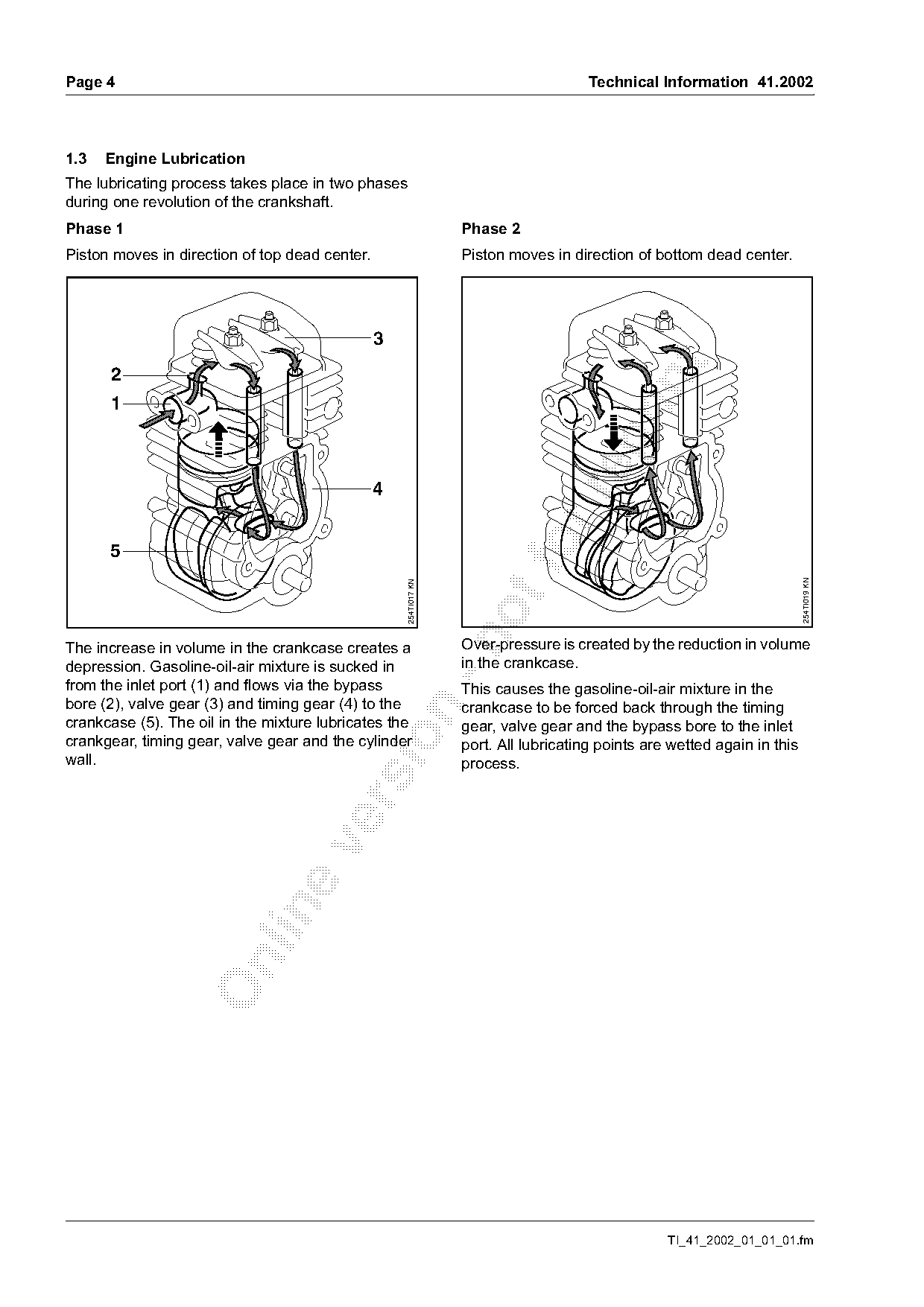
The lubricating process takes place in two phases
during one revolution of the crankshaft.
Phase 1                                                           Phase 2
Piston moves in direction of top dead center.                     Piston moves in direction of bottom dead center.


      5                                                                   fo

                                                                                                                          254TI019 KN
                                                    254TI017 KN

The increase in volume in the crankcase creates a                 Over-pressure is created by the reduction in volume
depression. Gasoline-oil-air mixture is sucked in                 in the crankcase.
from the inlet port (1) and flows via the bypass                  This causes the gasoline-oil-air mixture in the
bore (2), valve gear (3) and timing gear (4) to the               crankcase to be forced back through the timing

crankcase (5). The oil in the mixture lubricates the              gear, valve gear and the bypass bore to the inlet

crankgear, timing gear, valve gear and the cylinder               port. All lubricating points are wetted again in this
wall.                                                             process.

                                                                                                  TI_41_2002_01_01_01.fm
Page 5 of 21
Text of page 5 — search, copy, screen readers
Technical Information 41.2002                                                                       Page 5

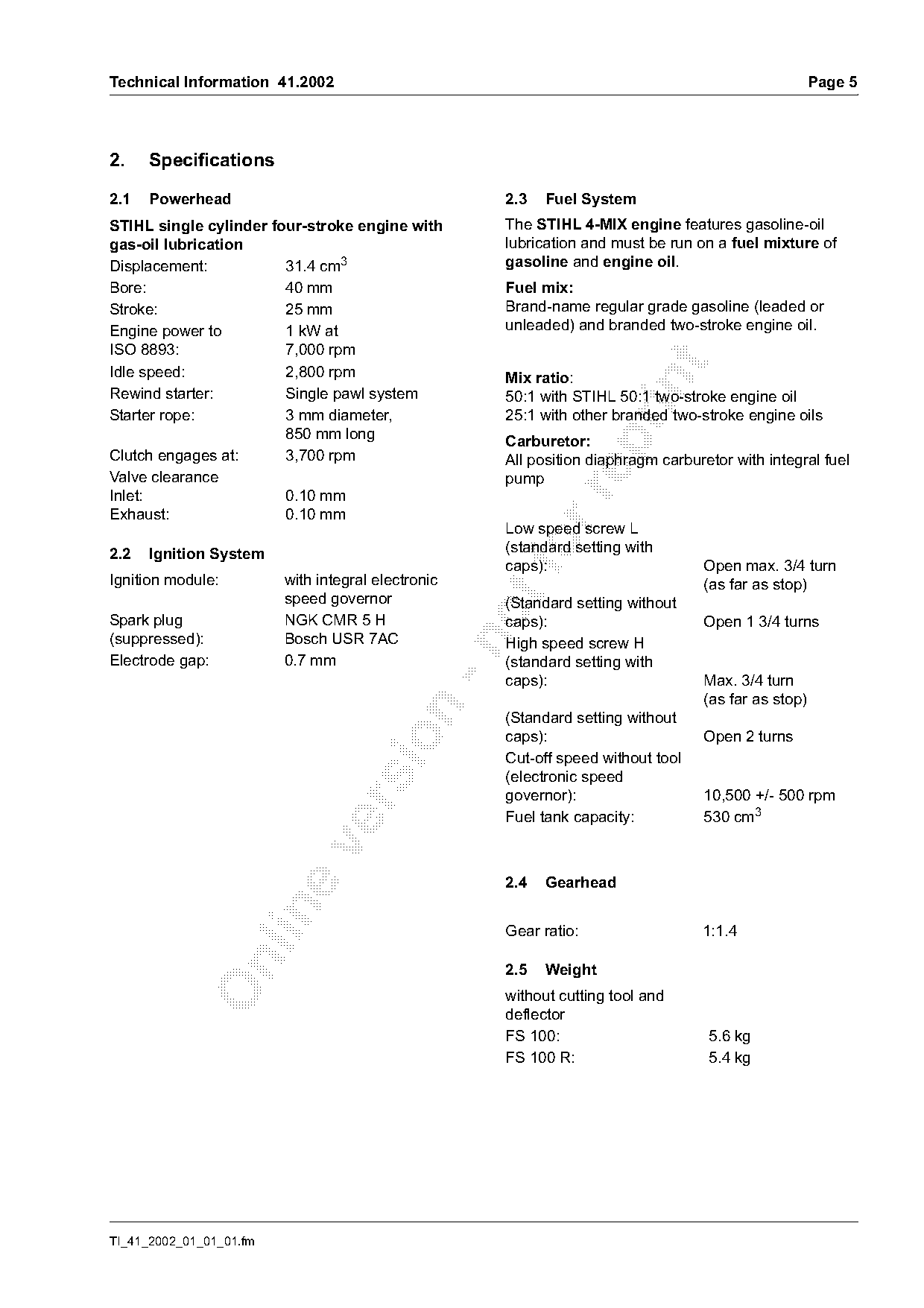
2.    Specifications

2.1   Powerhead                                     2.3   Fuel System
STIHL single cylinder four-stroke engine with       The STIHL 4-MIX engine features gasoline-oil
gas-oil lubrication                                 lubrication and must be run on a fuel mixture of
Displacement:           31.4 cm3                    gasoline and engine oil.
Bore:                   40 mm                       Fuel mix:
Stroke:                 25 mm                       Brand-name regular grade gasoline (leaded or
Engine power to         1 kW at                     unleaded) and branded two-stroke engine oil.
ISO 8893:               7,000 rpm

Idle speed:             2,800 rpm                   Mix ratio:

Rewind starter:         Single pawl system          50:1 with STIHL 50:1 two-stroke engine oil
Starter rope:           3 mm diameter,              25:1 with other branded two-stroke engine oils
                        850 mm long
                                                    Carburetor:

Clutch engages at:      3,700 rpm                   All position diaphragm carburetor with integral fuel
Valve clearance                                     pump

Inlet:                  0.10 mm
Exhaust:                0.10 mm
                                                    Low speed screw L
2.2   Ignition System                                fo
                                                    (standard setting with
                                                    caps):                       Open max. 3/4 turn
Ignition module:         with integral electronic                                (as far as stop)
                         speed governor
                                                    (Standard setting without
Spark plug               NGK CMR 5 H                caps):                       Open 1 3/4 turns
(suppressed):            Bosch USR 7AC

                                                    High speed screw H
Electrode gap:           0.7 mm                     (standard setting with
                                                    caps):                       Max. 3/4 turn
                                                                                 (as far as stop)

                                                    (Standard setting without
                                                    caps):                       Open 2 turns

                                                    Cut-off speed without tool
                                                    (electronic speed
                                                    governor):                   10,500 +/- 500 rpm

                                                    Fuel tank capacity:          530 cm3

                                                    2.4   Gearhead

                                                    Gear ratio:                  1:1.4

                                                    2.5   Weight
                                                    without cutting tool and
                                                    deflector
                                                    FS 100:                       5.6 kg
                                                    FS 100 R:                     5.4 kg

TI_41_2002_01_01_01.fm
Page 6 of 21
Text of page 6 — search, copy, screen readers
Page 6                                                                      Technical Information 41.2002

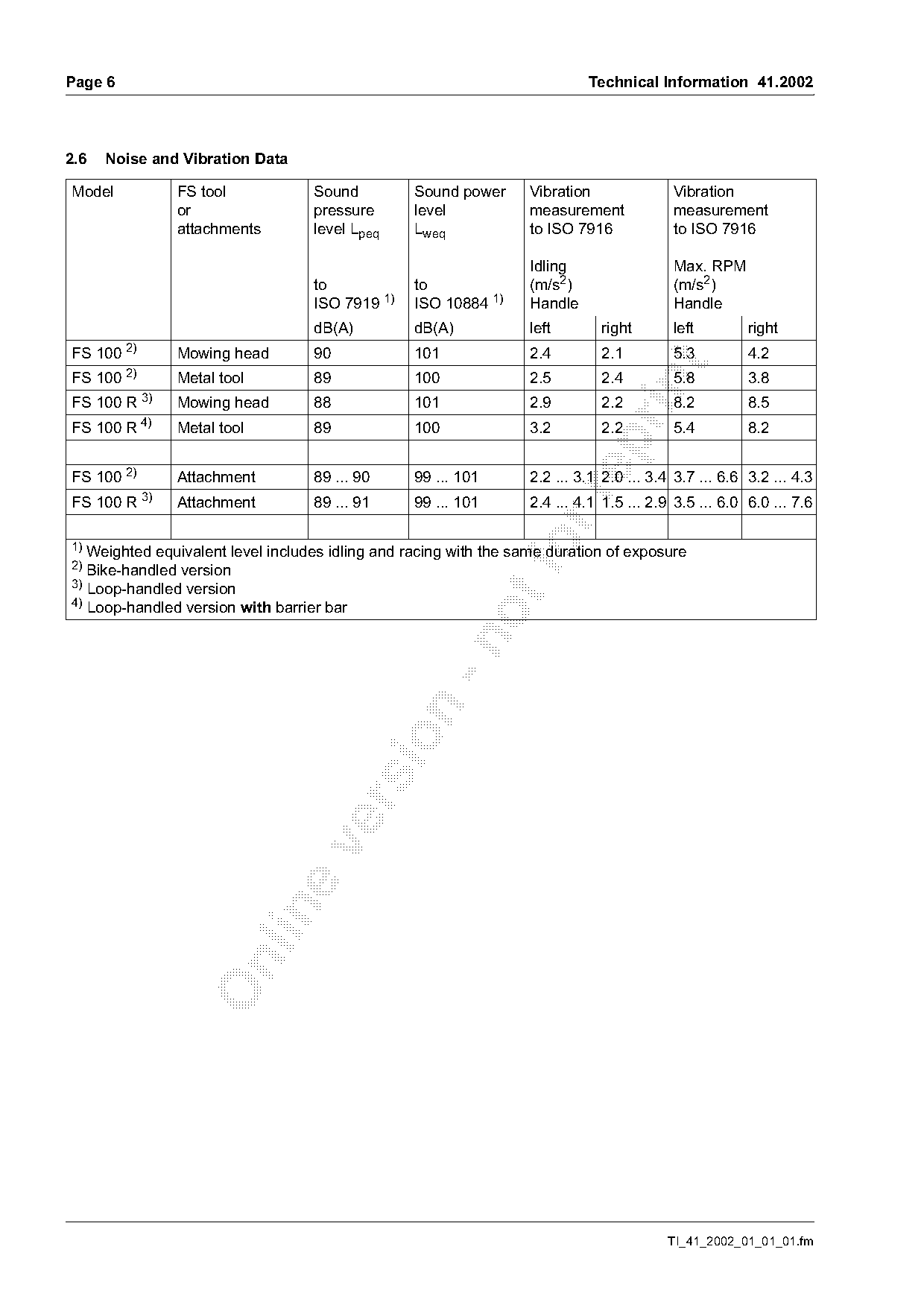
2.6   Noise and Vibration Data

Model              FS tool         Sound          Sound power     Vibration               Vibration
                   or              pressure       level           measurement             measurement
                   attachments     level Lpeq     Lweq            to ISO 7916             to ISO 7916

                                                                  Idling                  Max. RPM
                                   to             to              (m/s2)                  (m/s2)
                                   ISO 7919 1)    ISO 10884 1)    Handle                  Handle
                                   dB(A)          dB(A)           left        right       left         right
         2)
FS 100             Mowing head     90             101             2.4         2.1         5.3          4.2

FS 100 2)          Metal tool      89             100             2.5         2.4         5.8          3.8

FS 100 R 3)        Mowing head     88             101             2.9         2.2         8.2          8.5
              4)
FS 100 R           Metal tool      89             100             3.2         2.2         5.4          8.2

FS 100 2)          Attachment      89 ... 90      99 ... 101       2.2 ... 3.1 2.0 ... 3.4 3.7 ... 6.6 3.2 ... 4.3

              3)
FS 100 R           Attachment      89 ... 91      99 ... 101       2.4 ... 4.1 1.5 ... 2.9 3.5 ... 6.0 6.0 ... 7.6

1)
2)
   Weighted equivalent level includes idling and racing with the same duration of exposure
   Bike-handled version
3)
   Loop-handled version
4)
   Loop-handled version with barrier bar

                                                                                         TI_41_2002_01_01_01.fm
Page 7 of 21
Text of page 7 — search, copy, screen readers
Technical Information 41.2002                                                     Page 7

3.   Cutting Tools
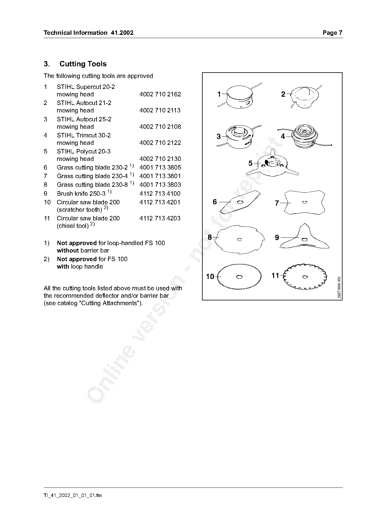
The following cutting tools are approved
1    STIHL Supercut 20-2
     mowing head                    4002 710 2162               1             2
2    STIHL Autocut 21-2
     mowing head                    4002 710 2113
3    STIHL Autocut 25-2
     mowing head                    4002 710 2108
4    STIHL Trimcut 30-2                                      3                4
     mowing head                    4002 710 2122

5    STIHL Polycut 20-3

     mowing head                    4002 710 2130
                                                                     5
6    Grass cutting blade 230-2 1)   4001 713 3805
7    Grass cutting blade 230-4 1)   4001 713 3801

8    Grass cutting blade 230-8 1)   4001 713 3803
9    Brush knife 250-3 1)           4112 713 4100

10   Circular saw blade 200         4112 713 4201           6            7
     (scratcher tooth) 2)
11   Circular saw blade 200
     (chisel tool) 2)
                                    4112 713 4203       fo
                                                        8                9
1)   Not approved for loop-handled FS 100
     without barrier bar

2)   Not approved for FS 100
     with loop handle
                                                        10               11

                                                                                      393TI006 KN

All the cutting tools listed above must be used with

the recommended deflector and/or barrier bar
(see catalog "Cutting Attachments").

TI_41_2002_01_01_01.fm
Page 8 of 21
Text of page 8 — search, copy, screen readers
Page 8                                                                  Technical Information 41.2002

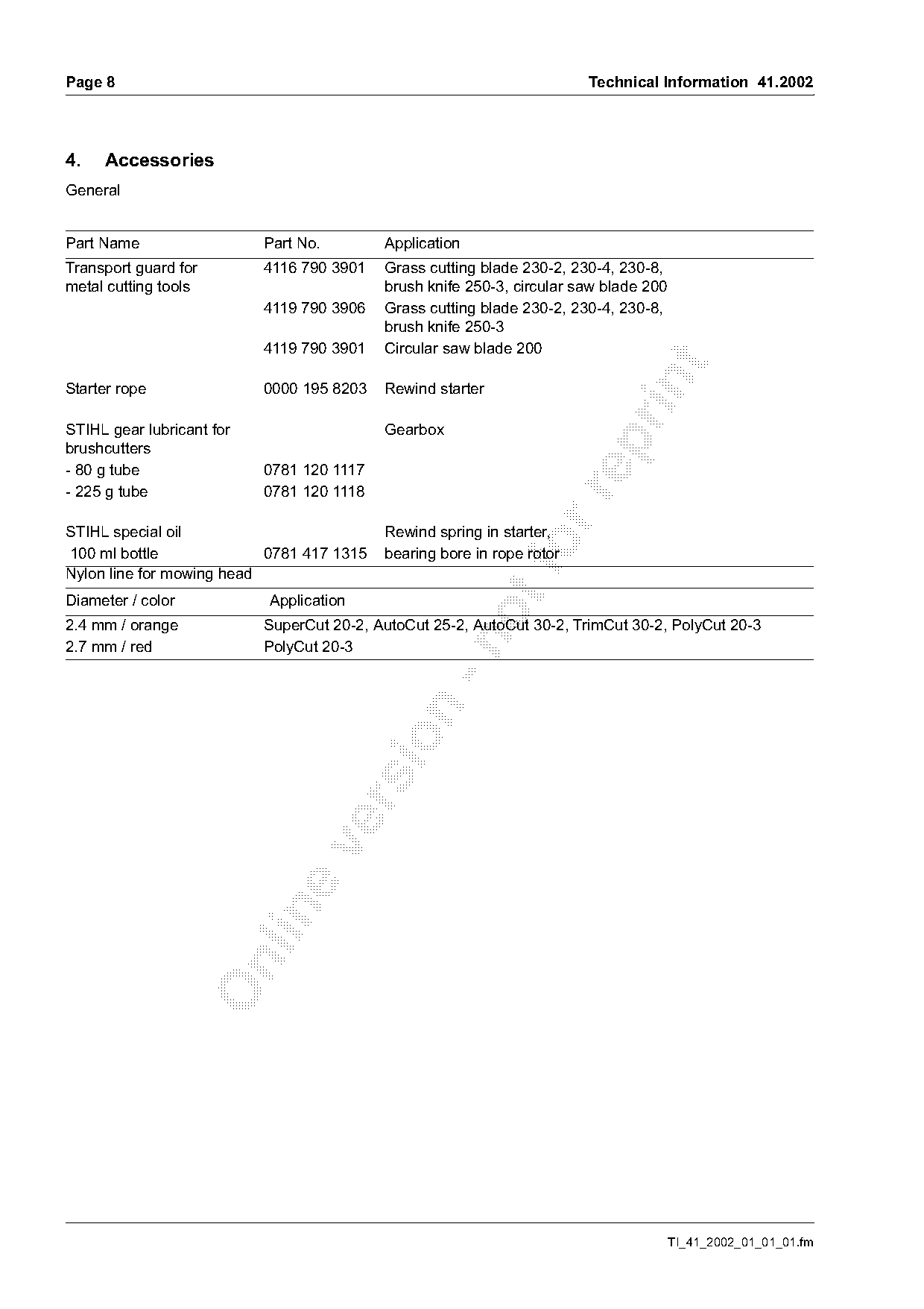
4.   Accessories
General

Part Name                  Part No.        Application
Transport guard for        4116 790 3901   Grass cutting blade 230-2, 230-4, 230-8,
metal cutting tools                        brush knife 250-3, circular saw blade 200
                           4119 790 3906   Grass cutting blade 230-2, 230-4, 230-8,
                                           brush knife 250-3
                           4119 790 3901   Circular saw blade 200

Starter rope               0000 195 8203   Rewind starter

STIHL gear lubricant for                   Gearbox

brushcutters
- 80 g tube                0781 120 1117
- 225 g tube               0781 120 1118

STIHL special oil                          Rewind spring in starter,
100 ml bottle
Nylon line for mowing head
                           0781 417 1315                      fo
                                           bearing bore in rope rotor
Diameter / color           Application
2.4 mm / orange            SuperCut 20-2, AutoCut 25-2, AutoCut 30-2, TrimCut 30-2, PolyCut 20-3

2.7 mm / red               PolyCut 20-3

                                                                                       TI_41_2002_01_01_01.fm
Page 9 of 21
Text of page 9 — search, copy, screen readers
Technical Information 41.2002                                                                          Page 9

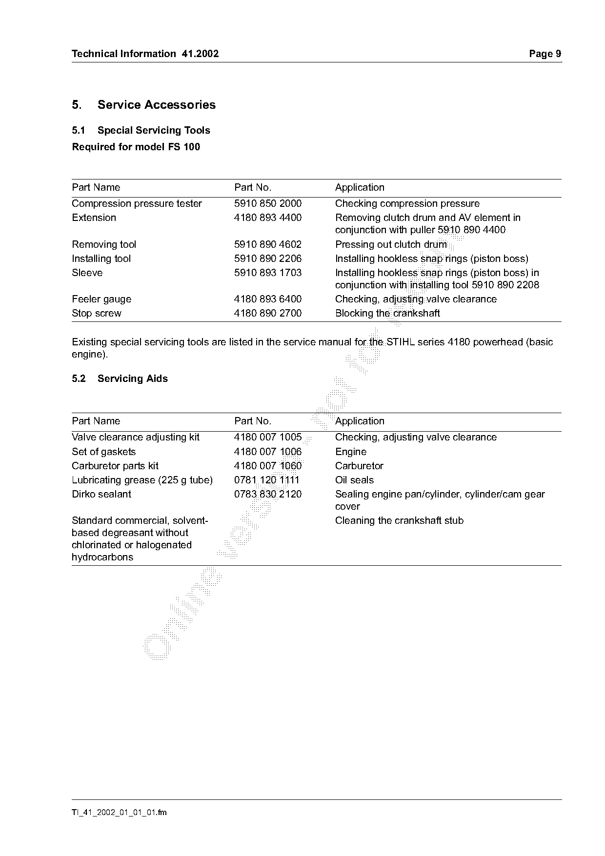
5.    Service Accessories

5.1   Special Servicing Tools
Required for model FS 100

Part Name                           Part No.               Application
Compression pressure tester         5910 850 2000          Checking compression pressure
Extension                           4180 893 4400          Removing clutch drum and AV element in
                                                           conjunction with puller 5910 890 4400

Removing tool                       5910 890 4602          Pressing out clutch drum

Installing tool                     5910 890 2206          Installing hookless snap rings (piston boss)
Sleeve                              5910 893 1703          Installing hookless snap rings (piston boss) in
                                                           conjunction with installing tool 5910 890 2208

Feeler gauge                        4180 893 6400          Checking, adjusting valve clearance
Stop screw                          4180 890 2700          Blocking the crankshaft

Existing special servicing tools are listed in the service manual for the STIHL series 4180 powerhead (basic
engine).

5.2   Servicing Aids

Part Name                           Part No.               Application
Valve clearance adjusting kit       4180 007 1005          Checking, adjusting valve clearance
Set of gaskets                      4180 007 1006          Engine

Carburetor parts kit                4180 007 1060          Carburetor
Lubricating grease (225 g tube)     0781 120 1111          Oil seals

Dirko sealant                       0783 830 2120          Sealing engine pan/cylinder, cylinder/cam gear
                                                           cover
Standard commercial, solvent-                              Cleaning the crankshaft stub

based degreasant without
chlorinated or halogenated

hydrocarbons

TI_41_2002_01_01_01.fm
Page 10 of 21
Text of page 10 — search, copy, screen readers
Page 10                                                                               Technical Information 41.2002

6.     Service Note
If the machine is started up in the course of repairs,
it is essential to observe all country-specific safety
regulations and the safety precautions outlined in                                           6
the instruction manual.

6.1    Checking Valve Clearance
                                                                                             5
The valve clearance must be checked once after
about 135 hours of operation and adjusted if                                                               4

                                                                                                                        254TI002 KN
necessary.                                                                           4
Check and adjust valve clearance only when the

engine is cold. Use the valve clearance adjusting kit

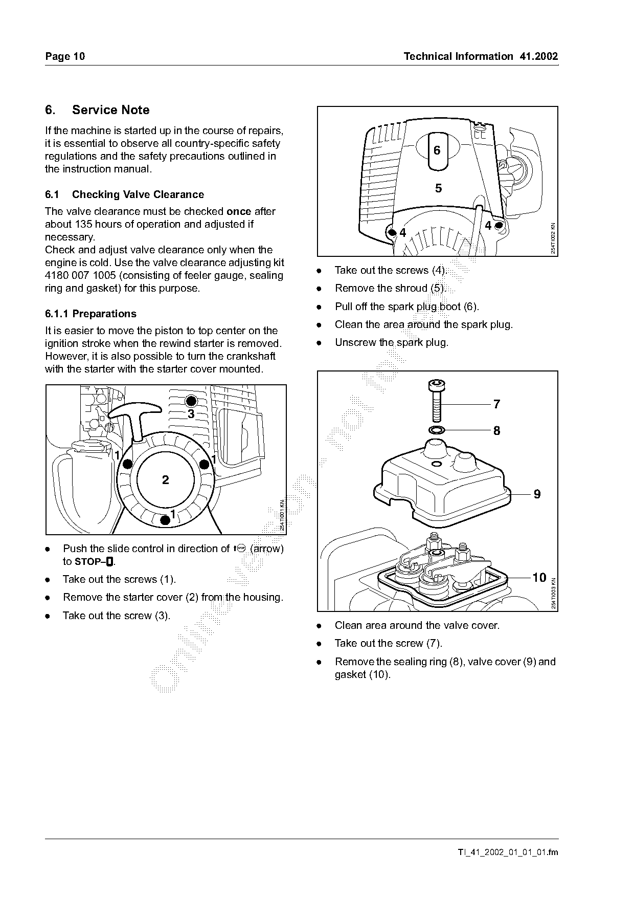
4180 007 1005 (consisting of feeler gauge, sealing                 .   Take out the screws (4).
ring and gasket) for this purpose.                                 .   Remove the shroud (5).

                                                                   .   Pull off the spark plug boot (6).
6.1.1 Preparations
                                                                   .   Clean the area around the spark plug.
It is easier to move the piston to top center on the

ignition stroke when the rewind starter is removed.                .   Unscrew the spark plug.
However, it is also possible to turn the crankshaft
with the starter with the starter cover mounted.
                                                                                                               7
                                   3
                                                                                                               8

                 1                     1
                           2

                                                                                                                   9
                                                     254TI001 KN


.     Push the slide control in direction of c (arrow)

      to STOP–$
              $.
.     Take out the screws (1).                                                                                     10

                                                                                                                         254TI003 KN

.     Remove the starter cover (2) from the housing.
.     Take out the screw (3).
                                                                   .   Clean area around the valve cover.

                                                                   .   Take out the screw (7).
                                                                   .   Remove the sealing ring (8), valve cover (9) and

                                                                       gasket (10).

                                                                                                   TI_41_2002_01_01_01.fm
Page 11 of 21
Text of page 11 — search, copy, screen readers
Technical Information 41.2002                                                                                Page 11

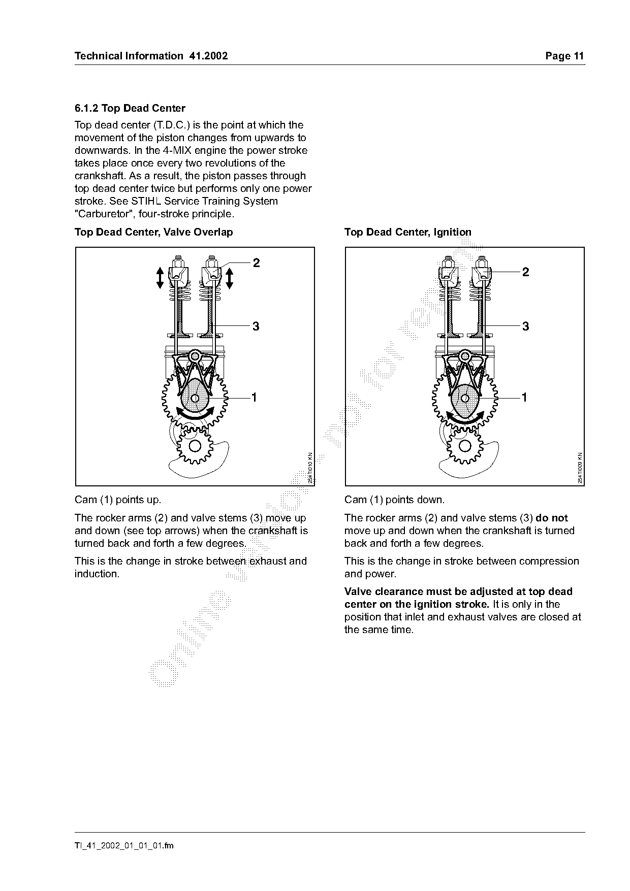
6.1.2 Top Dead Center
Top dead center (T.D.C.) is the point at which the
movement of the piston changes from upwards to
downwards. In the 4-MIX engine the power stroke
takes place once every two revolutions of the
crankshaft. As a result, the piston passes through
top dead center twice but performs only one power
stroke. See STIHL Service Training System
"Carburetor", four-stroke principle.
Top Dead Center, Valve Overlap                                   Top Dead Center, Ignition

                                     2
                                                                                                        2

                                     3                                                                  3

                                     1                                                                 1
                                               -n  254TI010 KN

                                                                                                                    254TI009 KN

Cam (1) points up.                                               Cam (1) points down.

The rocker arms (2) and valve stems (3) move up                  The rocker arms (2) and valve stems (3) do not
and down (see top arrows) when the crankshaft is                 move up and down when the crankshaft is turned
turned back and forth a few degrees.                             back and forth a few degrees.

This is the change in stroke between exhaust and                 This is the change in stroke between compression
induction.                                                       and power.

                                                                 Valve clearance must be adjusted at top dead
                                                                 center on the ignition stroke. It is only in the
                                                                 position that inlet and exhaust valves are closed at

                                                                 the same time.

TI_41_2002_01_01_01.fm
Page 12 of 21
Text of page 12 — search, copy, screen readers
Page 12                                                                                   Technical Information 41.2002

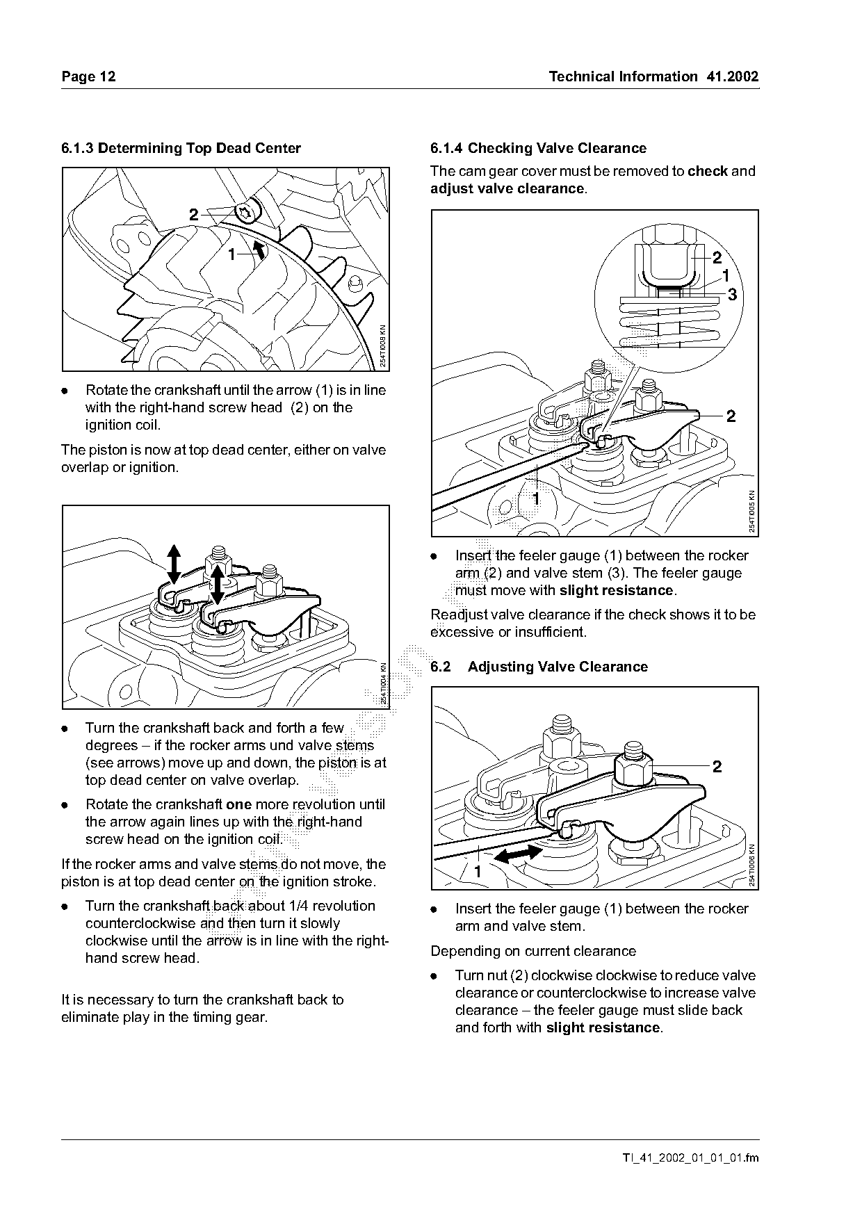
6.1.3 Determining Top Dead Center                                   6.1.4 Checking Valve Clearance
                                                                    The cam gear cover must be removed to check and
                                                                    adjust valve clearance.
                     2

                            1                                                                                      2
                                                                                                                    1
                                                                                                                     3

                                                      254TI008 KN

.   Rotate the crankshaft until the arrow (1) is in line
    with the right-hand screw head (2) on the

    ignition coil.
                                                                                                                       2
The piston is now at top dead center, either on valve

overlap or ignition.

                                                                                                                           254TI005 KN
                                                                                      1
                                                                    .     Insert the feeler gauge (1) between the rocker
                                                                          arm (2) and valve stem (3). The feeler gauge
                                                                          must move with slight resistance.

                                                                    Readjust valve clearance if the check shows it to be
                                                                    excessive or insufficient.

                                                                    6.2    Adjusting Valve Clearance
                                                      254TI004 KN

.   Turn the crankshaft back and forth a few
    degrees – if the rocker arms und valve stems

    (see arrows) move up and down, the piston is at                                                                2
    top dead center on valve overlap.

.   Rotate the crankshaft one more revolution until
    the arrow again lines up with the right-hand
    screw head on the ignition coil.

                                                                                                                           254TI006 KN

If the rocker arms and valve stems do not move, the
                                                                            1
piston is at top dead center on the ignition stroke.

.   Turn the crankshaft back about 1/4 revolution                   .     Insert the feeler gauge (1) between the rocker
    counterclockwise and then turn it slowly                              arm and valve stem.
    clockwise until the arrow is in line with the right-
    hand screw head.                                                Depending on current clearance
                                                                    .     Turn nut (2) clockwise clockwise to reduce valve
It is necessary to turn the crankshaft back to                            clearance or counterclockwise to increase valve
eliminate play in the timing gear.                                        clearance – the feeler gauge must slide back
                                                                          and forth with slight resistance.

                                                                                                    TI_41_2002_01_01_01.fm
Page 13 of 21
Text of page 13 — search, copy, screen readers
Technical Information 41.2002                                                                                     Page 13

.     Rotate crankshaft two revolutions until the                  6.4     Checking Compression Pressure
      arrow again lines up with the right-hand screw               .     Pull the boot off the spark plug and then
      head on the ignition coil.                                         unscrew the spark plug.
.     Check valve clearance again and readjust if
      necessary.

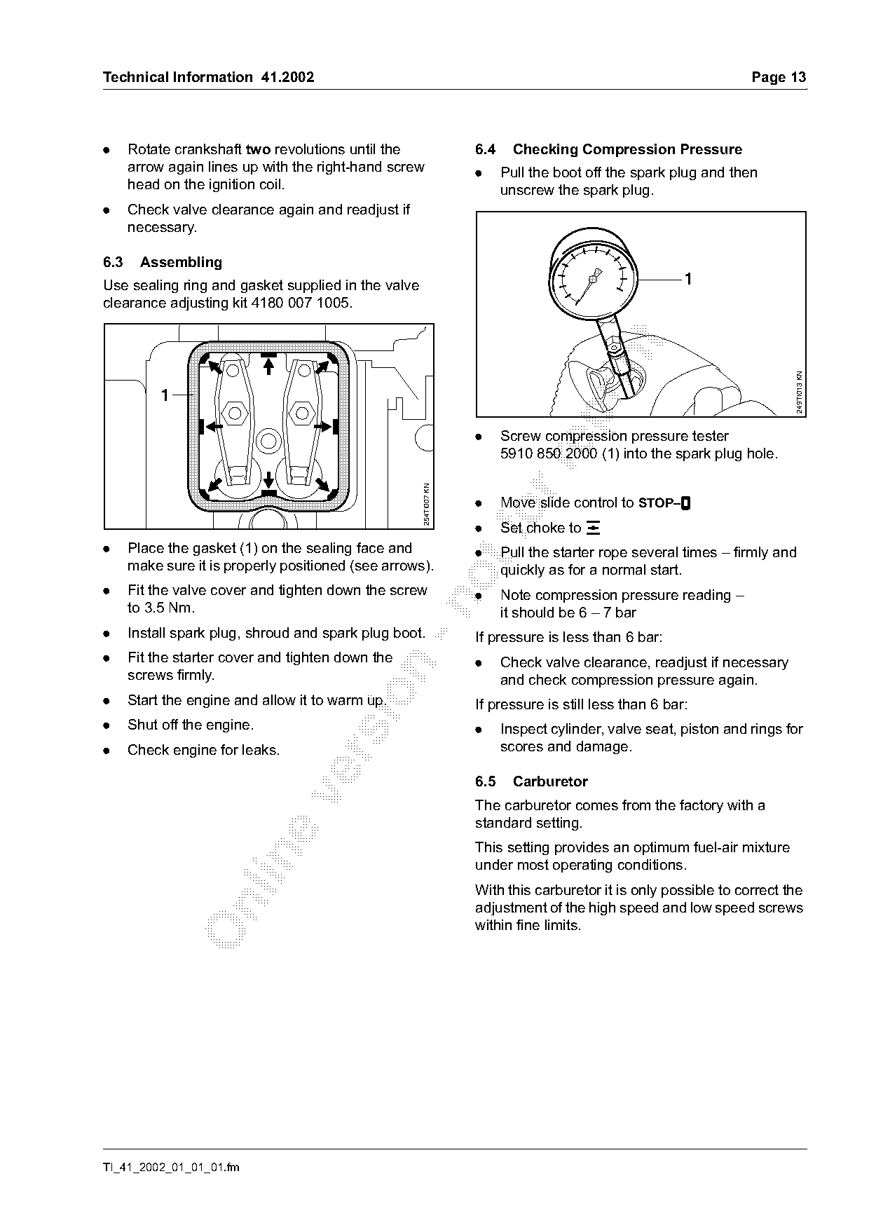
6.3    Assembling
Use sealing ring and gasket supplied in the valve                                                      1
clearance adjusting kit 4180 007 1005.

                                                                                                                         249TI013 KN
           1

                                                                   .     Screw compression pressure tester
                                                                         5910 850 2000 (1) into the spark plug hole.

                                                     254TI007 KN

                                                                   .     Move slide control to STOP–$
                                                                                                    $
                                                                   .
                                                                       foSet choke to e
.     Place the gasket (1) on the sealing face and                 .     Pull the starter rope several times – firmly and
      make sure it is properly positioned (see arrows).                  quickly as for a normal start.
.     Fit the valve cover and tighten down the screw               .     Note compression pressure reading –

      to 3.5 Nm.                                                         it should be 6 – 7 bar
.     Install spark plug, shroud and spark plug boot.              If pressure is less than 6 bar:
.     Fit the starter cover and tighten down the                   .     Check valve clearance, readjust if necessary

      screws firmly.                                                     and check compression pressure again.

.     Start the engine and allow it to warm up.                    If pressure is still less than 6 bar:
.     Shut off the engine.                                         .     Inspect cylinder, valve seat, piston and rings for
.     Check engine for leaks.                                            scores and damage.

                                                                   6.5     Carburetor

                                                                   The carburetor comes from the factory with a
                                                                   standard setting.
                                                                   This setting provides an optimum fuel-air mixture

                                                                   under most operating conditions.
                                                                   With this carburetor it is only possible to correct the

                                                                   adjustment of the high speed and low speed screws
                                                                   within fine limits.

TI_41_2002_01_01_01.fm
Page 14 of 21
Text of page 14 — search, copy, screen readers
Page 14                                                                               Technical Information 41.2002

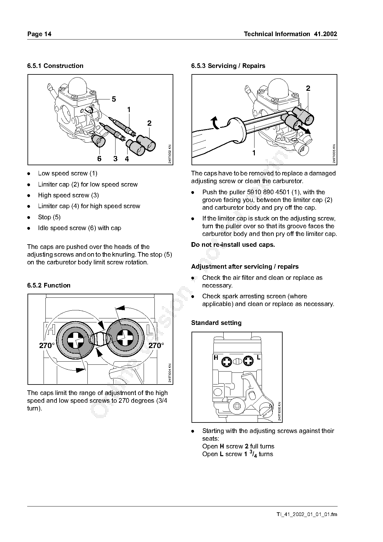
6.5.1 Construction                                                 6.5.3 Servicing / Repairs

                                                                                                                 2
                              5
                                    1
                                            2

                                                                                                                        249TI005 KN
                                                     249TI002 KN


                         6     3 4
.   Low speed screw (1)                                            The caps have to be removed to replace a damaged
                                                                   adjusting screw or clean the carburetor.

.   Limiter cap (2) for low speed screw
.   High speed screw (3)                                           .   Push the puller 5910 890 4501 (1), with the
                                                                       groove facing you, between the limiter cap (2)

.   Limiter cap (4) for high speed screw                               and carburetor body and pry off the cap.
.   Stop (5)                                                       .   If the limiter cap is stuck on the adjusting screw,
.   Idle speed screw (6) with cap                                          fo
                                                                       turn the puller over so that its groove faces the
                                                                       carburetor body and then pry off the limiter cap.

The caps are pushed over the heads of the                          Do not re-install used caps.
adjusting screws and on to the knurling. The stop (5)
on the carburetor body limit screw rotation.

                                                                   Adjustment after servicing / repairs
                                                                   .   Check the air filter and clean or replace as
6.5.2 Function                                                         necessary.

                                                                   .   Check spark arresting screen (where
                                                                       applicable) and clean or replace as necessary.

                                                                   Standard setting

    270°                                    270°

                                                                           H                 L
                                                     249TI004 KN

The caps limit the range of adjustment of the high

speed and low speed screws to 270 degrees (3/4
                                                                                                   249TI006 KN

turn).

                                                                   .   Starting with the adjusting screws against their
                                                                       seats:
                                                                       Open H screw 2 full turns
                                                                       Open L screw 1 3/4 turns

                                                                                                   TI_41_2002_01_01_01.fm
Page 15 of 21
Text of page 15 — search, copy, screen readers
Technical Information 41.2002                                                                                  Page 15

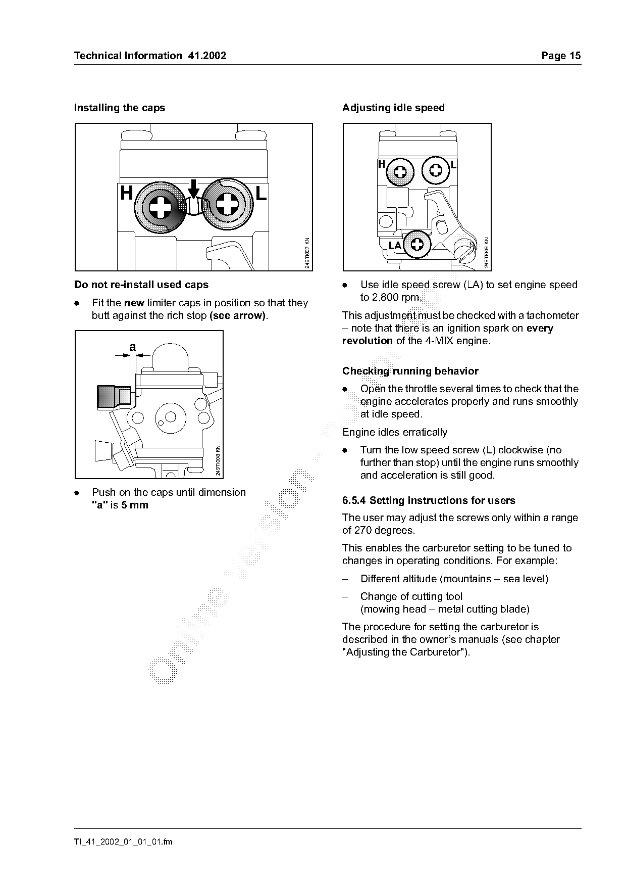
Installing the caps                                               Adjusting idle speed

                                                                          H                  L

          H                                    L

                                                                                                 249TI009 KN
                                                    249TI007 KN
                                                                              LA

Do not re-install used caps                                       .   Use idle speed screw (LA) to set engine speed
                                                                      to 2,800 rpm.

.   Fit the new limiter caps in position so that they
    butt against the rich stop (see arrow).                       This adjustment must be checked with a tachometer
                                                                  – note that there is an ignition spark on every

                                                                  revolution of the 4-MIX engine.
            a

                                                                  .
                                                                  Checking running behavior
                                                                      Open the throttle several times to check that the
                                                                      engine accelerates properly and runs smoothly
                                                                      at idle speed.
                                                                  Engine idles erratically

                                                                  .   Turn the low speed screw (L) clockwise (no
                                249TI008 KN

                                                                      further than stop) until the engine runs smoothly
                                                                      and acceleration is still good.

.   Push on the caps until dimension
                                                                  6.5.4 Setting instructions for users

    "a" is 5 mm
                                                                  The user may adjust the screws only within a range
                                                                  of 270 degrees.

                                                                  This enables the carburetor setting to be tuned to
                                                                  changes in operating conditions. For example:

                                                                  –   Different altitude (mountains – sea level)
                                                                  –   Change of cutting tool
                                                                      (mowing head – metal cutting blade)

                                                                  The procedure for setting the carburetor is
                                                                  described in the owner’s manuals (see chapter
                                                                  "Adjusting the Carburetor").

TI_41_2002_01_01_01.fm
Page 16 of 21
Text of page 16 — search, copy, screen readers
Page 16                                                                                    Technical Information 41.2002

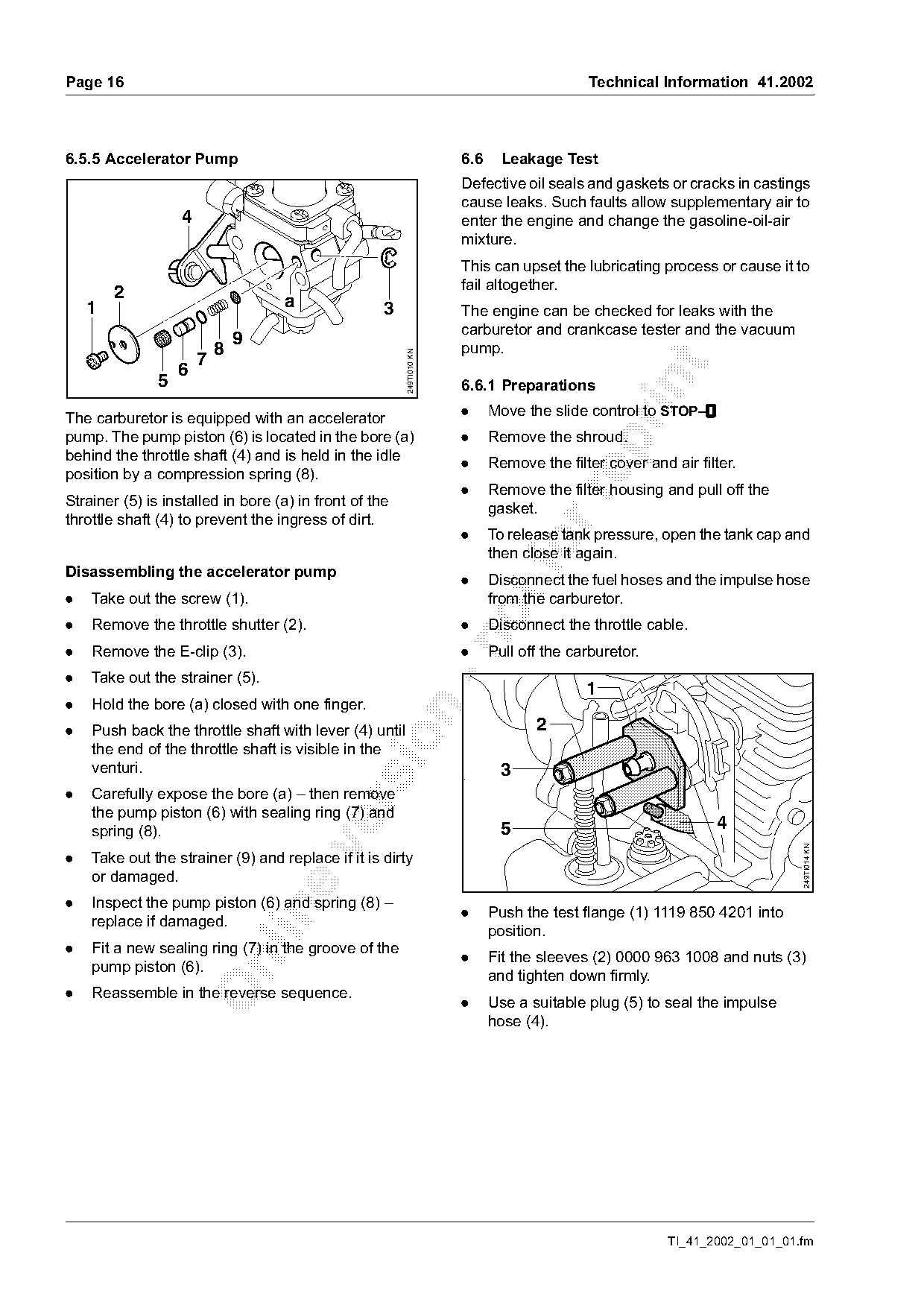
6.5.5 Accelerator Pump                                                6.6     Leakage Test
                                                                      Defective oil seals and gaskets or cracks in castings
                                                                      cause leaks. Such faults allow supplementary air to
                   4                                                  enter the engine and change the gasoline-oil-air
                                                                      mixture.
                                                                      This can upset the lubricating process or cause it to
                                                                      fail altogether.
        2                           a
    1                                               3                 The engine can be checked for leaks with the
                                                                      carburetor and crankcase tester and the vacuum
                               9                                      pump.
                           8

                                                        249TI010 KN
                       7

                   6
               5

                                                                      6.6.1 Preparations
                                                                      .     Move the slide control to STOP–$
                                                                                                           $
The carburetor is equipped with an accelerator
pump. The pump piston (6) is located in the bore (a)                  .     Remove the shroud.

behind the throttle shaft (4) and is held in the idle                 .     Remove the filter cover and air filter.
position by a compression spring (8).
                                                                      .     Remove the filter housing and pull off the

Strainer (5) is installed in bore (a) in front of the                       gasket.
throttle shaft (4) to prevent the ingress of dirt.
                                                                      .     To release tank pressure, open the tank cap and

Disassembling the accelerator pump
                                                                            then close it again.
                                                                      .     Disconnect the fuel hoses and the impulse hose
.   Take out the screw (1).                                                 from the carburetor.

.   Remove the throttle shutter (2).                                  .     Disconnect the throttle cable.

.   Remove the E-clip (3).                                            .     Pull off the carburetor.
.   Take out the strainer (5).
                                                                                           1
.   Hold the bore (a) closed with one finger.

.   Push back the throttle shaft with lever (4) until                              2

    the end of the throttle shaft is visible in the
    venturi.                                                                  3
.   Carefully expose the bore (a) – then remove

    the pump piston (6) with sealing ring (7) and
    spring (8).                                                               5                                4

                                                                                                                            249TI014 KN

.   Take out the strainer (9) and replace if it is dirty
    or damaged.
.   Inspect the pump piston (6) and spring (8) –

                                                                      .     Push the test flange (1) 1119 850 4201 into
    replace if damaged.
                                                                            position.
.   Fit a new sealing ring (7) in the groove of the
                                                                      .     Fit the sleeves (2) 0000 963 1008 and nuts (3)

    pump piston (6).
                                                                            and tighten down firmly.
.   Reassemble in the reverse sequence.
                                                                      .     Use a suitable plug (5) to seal the impulse
                                                                            hose (4).

                                                                                                        TI_41_2002_01_01_01.fm
Page 17 of 21
Text of page 17 — search, copy, screen readers
Technical Information 41.2002                                                                                    Page 17

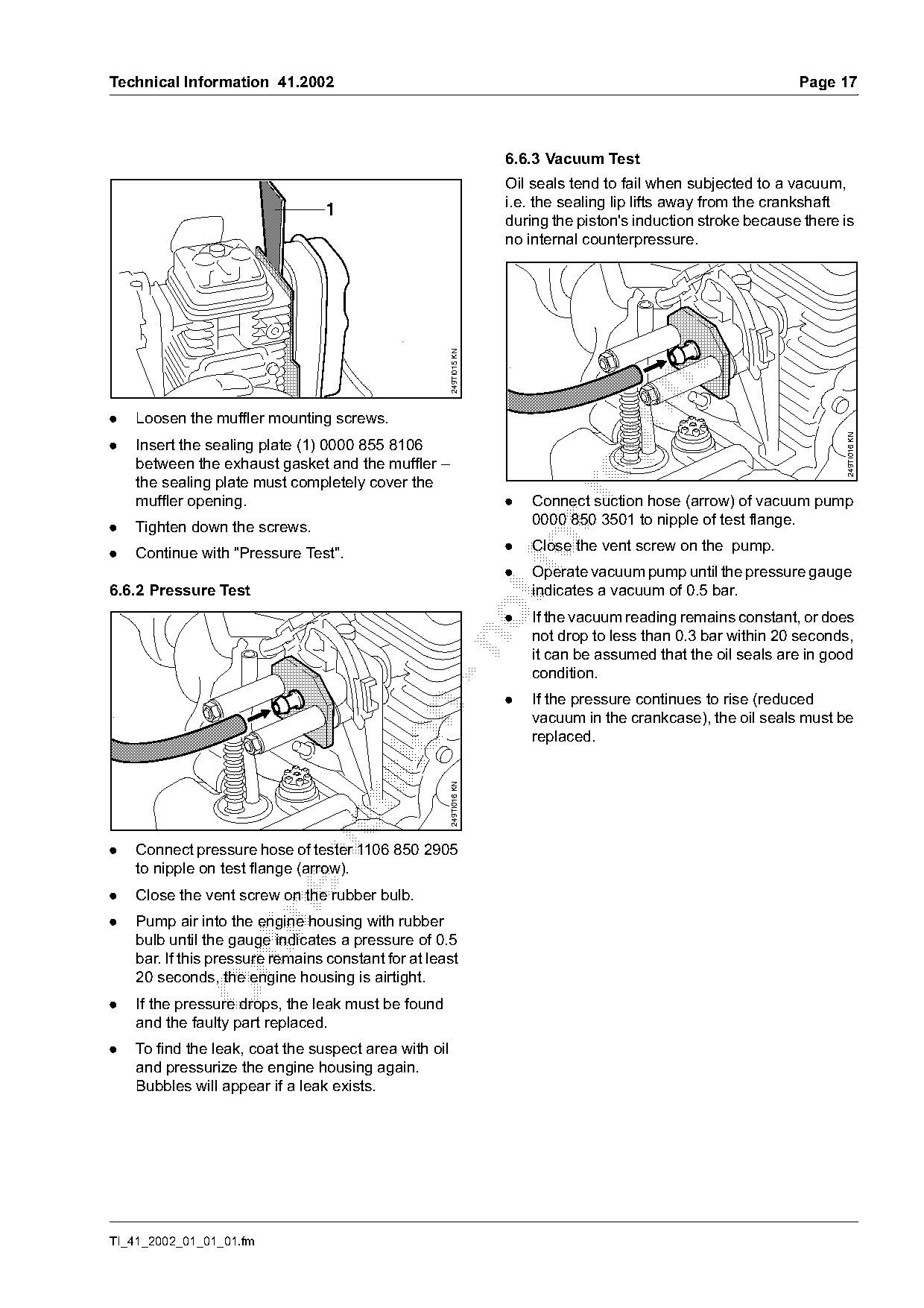
                                                                     6.6.3 Vacuum Test
                                                                     Oil seals tend to fail when subjected to a vacuum,
                                                                     i.e. the sealing lip lifts away from the crankshaft
                                 1
                                                                     during the piston's induction stroke because there is
                                                                     no internal counterpressure.

                                                       249TI015 KN

.   Loosen the muffler mounting screws.

                                                                                                                        249TI016 KN
.   Insert the sealing plate (1) 0000 855 8106
    between the exhaust gasket and the muffler –
    the sealing plate must completely cover the

    muffler opening.                                                 .   Connect suction hose (arrow) of vacuum pump
.   Tighten down the screws.                                             0000 850 3501 to nipple of test flange.

.   Continue with "Pressure Test".
                                                                     .
                                                                     .
                                                                         Close the vent screw on the pump.
                                                                         Operate vacuum pump until the pressure gauge
6.6.2 Pressure Test                                                      indicates a vacuum of 0.5 bar.
                                                                     .   If the vacuum reading remains constant, or does
                                                                         not drop to less than 0.3 bar within 20 seconds,

                                                                         it can be assumed that the oil seals are in good
                                                                         condition.
                                                                     .   If the pressure continues to rise (reduced

                                                                         vacuum in the crankcase), the oil seals must be
                                                                         replaced.
                                                       249TI016 KN

.   Connect pressure hose of tester 1106 850 2905
    to nipple on test flange (arrow).
.   Close the vent screw on the rubber bulb.

.   Pump air into the engine housing with rubber
    bulb until the gauge indicates a pressure of 0.5
    bar. If this pressure remains constant for at least

    20 seconds, the engine housing is airtight.
.   If the pressure drops, the leak must be found
    and the faulty part replaced.
.   To find the leak, coat the suspect area with oil
    and pressurize the engine housing again.
    Bubbles will appear if a leak exists.

TI_41_2002_01_01_01.fm
Page 18 of 21
Text of page 18 — search, copy, screen readers
Page 18                                                                                          Technical Information 41.2002

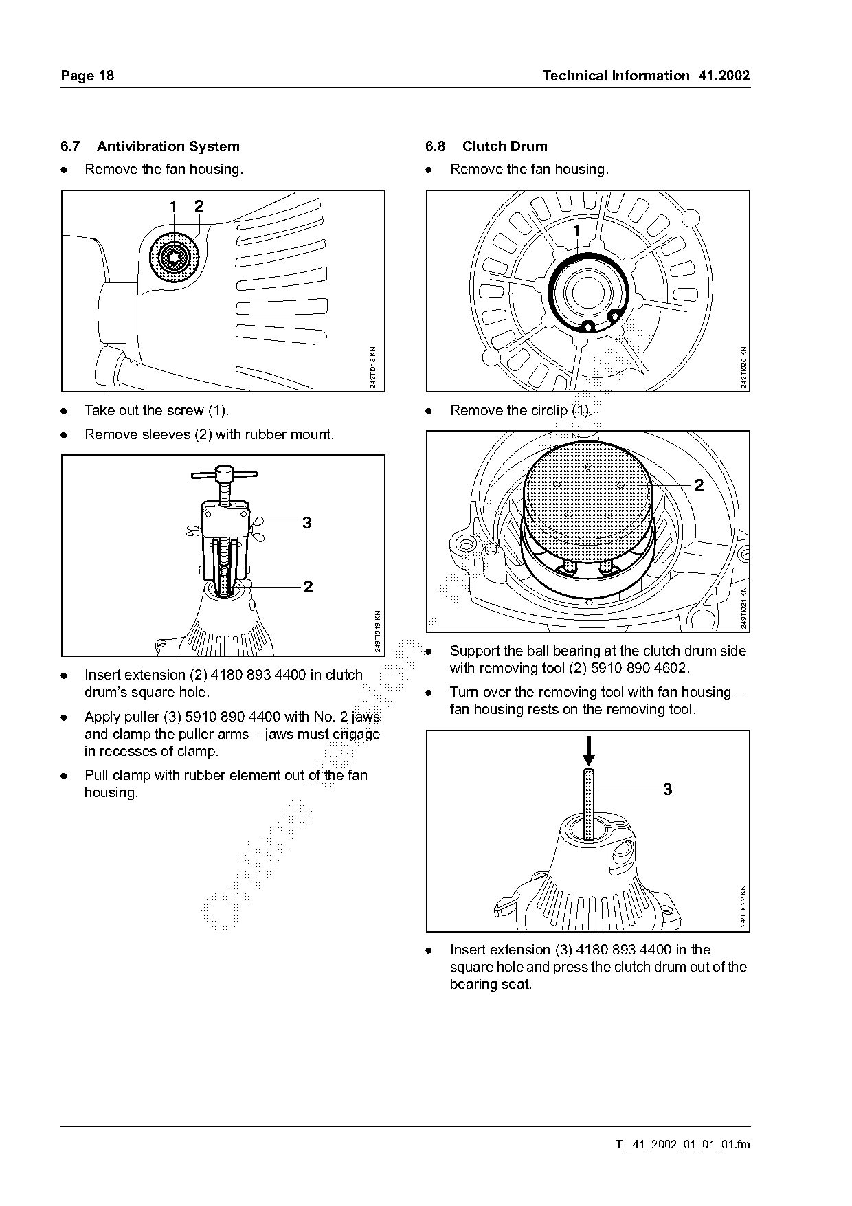
6.7    Antivibration System                                                 6.8    Clutch Drum
.     Remove the fan housing.                                               .     Remove the fan housing.

                   1 2
                                                                                                     1

                                                                                                                                 249TI020 KN
                                                      249TI018 KN

.     Take out the screw (1).                                               .     Remove the circlip (1).
.     Remove sleeves (2) with rubber mount.


                                                                                                                                 249TI021 KN
                                                              249TI019 KN

                                                                            .     Support the ball bearing at the clutch drum side

                                                                                  with removing tool (2) 5910 890 4602.
.     Insert extension (2) 4180 893 4400 in clutch

      drum’s square hole.                                                   .     Turn over the removing tool with fan housing –
                                                                                  fan housing rests on the removing tool.
.     Apply puller (3) 5910 890 4400 with No. 2 jaws
      and clamp the puller arms – jaws must engage

      in recesses of clamp.
.     Pull clamp with rubber element out of the fan

      housing.                                                                                                      3

                                                                                                                                 249TI022 KN

                                                                            .     Insert extension (3) 4180 893 4400 in the
                                                                                  square hole and press the clutch drum out of the
                                                                                  bearing seat.

                                                                                                            TI_41_2002_01_01_01.fm
Page 19 of 21
Text of page 19 — search, copy, screen readers
Technical Information 41.2002                                                                                      Page 19

                                                                     Testing the ignition system
                            5                                        To test the ignition system, use either the ZAT 4
                                                                     ignition system tester 5910 850 4503 or the ZAT 3
                                                                     ignition system tester 5910 850 4520.
                                                                     The ignition test refers only to the spark test.
                                                                     A new ignition module must be installed if no ignition
                                                                     spark is obtained even though the wiring and stop
                                                                     switch are in good condition.

                                                      249TI023 KN
                                                                     Ignition timing
                                4
                                                                     The ignition module accommodates all the

                                                                     components required to control ignition timing.
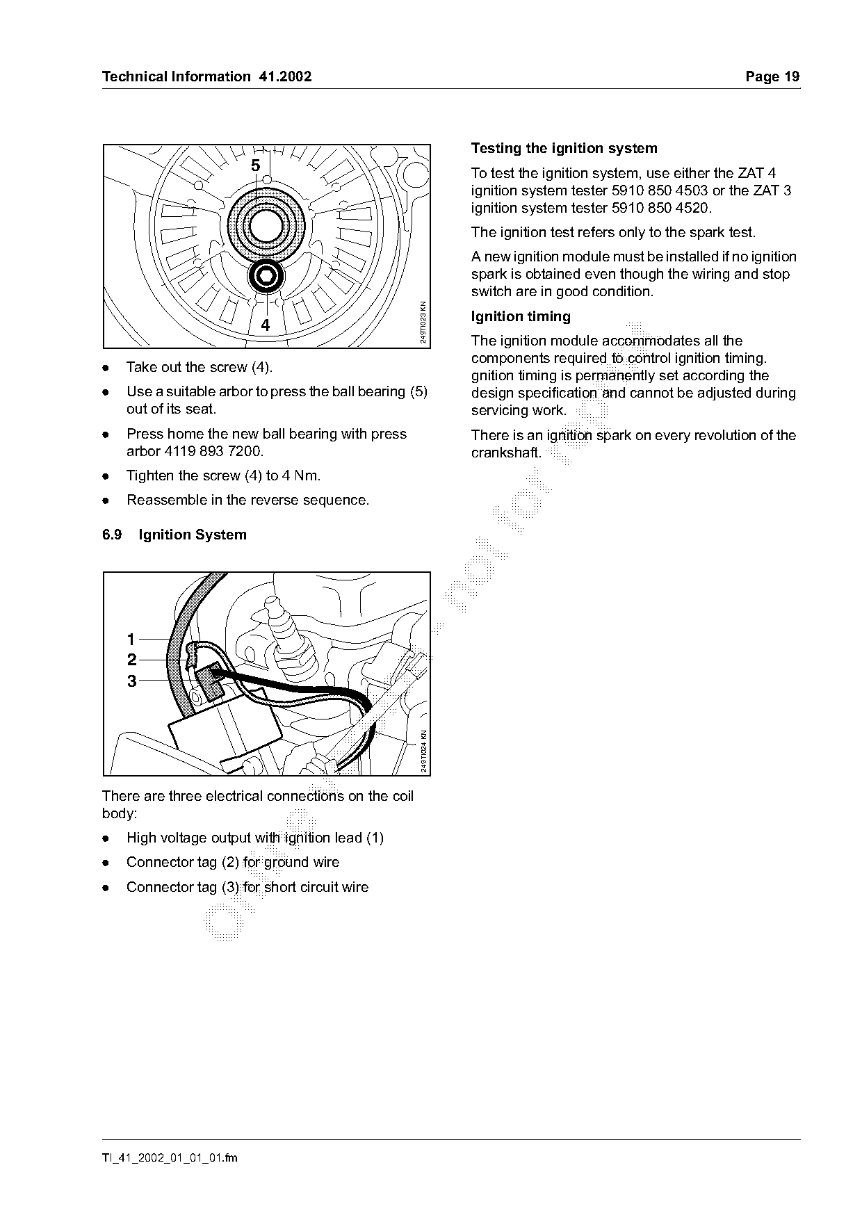
.     Take out the screw (4).
                                                                     gnition timing is permanently set according the
.     Use a suitable arbor to press the ball bearing (5)             design specification and cannot be adjusted during
      out of its seat.                                               servicing work.

.     Press home the new ball bearing with press                     There is an ignition spark on every revolution of the
      arbor 4119 893 7200.                                           crankshaft.

.     Tighten the screw (4) to 4 Nm.
.     Reassemble in the reverse sequence.

6.9       Ignition System

      1
      2

      3
                                                       249TI024 KN

There are three electrical connections on the coil
body:
.     High voltage output with ignition lead (1)

.     Connector tag (2) for ground wire
.     Connector tag (3) for short circuit wire

TI_41_2002_01_01_01.fm
Page 20 of 21
Text of page 20 — search, copy, screen readers
Page 20                                                                               Technical Information 41.2002

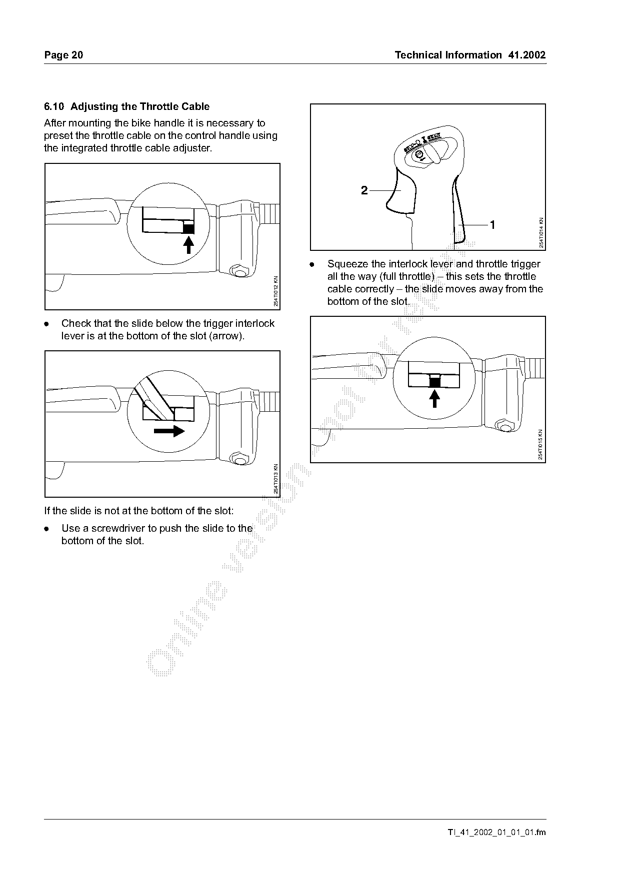
6.10 Adjusting the Throttle Cable
After mounting the bike handle it is necessary to
preset the throttle cable on the control handle using
the integrated throttle cable adjuster.                                                    STO


                                                                                                                          254TI014 KN
                                                                                                             1

                                                                  .   Squeeze the interlock lever and throttle trigger
                                                    254TI012 KN
                                                                      all the way (full throttle) – this sets the throttle
                                                                      cable correctly – the slide moves away from the

                                                                      bottom of the slot.

.   Check that the slide below the trigger interlock

    lever is at the bottom of the slot (arrow).

                                                                                                                        254TI015 KN
                                                    254TI013 KN

If the slide is not at the bottom of the slot:
.   Use a screwdriver to push the slide to the

    bottom of the slot.

                                                                                                   TI_41_2002_01_01_01.fm
Page 21 of 21
Text of page 21 — search, copy, screen readers
Technical Information 41.2002                                                                        Page 21

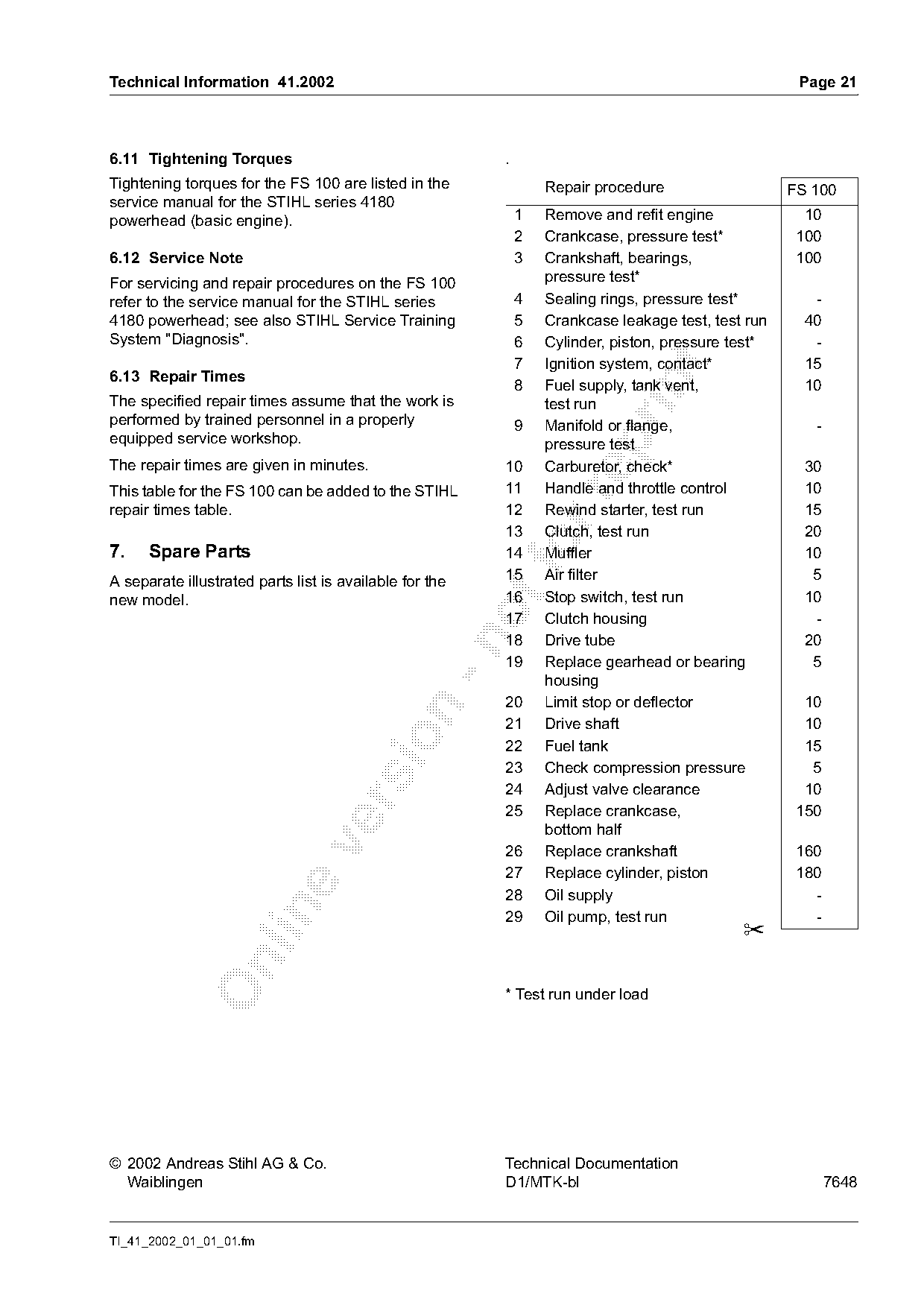
6.11 Tightening Torques                                  .
Tightening torques for the FS 100 are listed in the              Repair procedure                   FS 100
service manual for the STIHL series 4180
powerhead (basic engine).                                    1   Remove and refit engine              10
                                                             2   Crankcase, pressure test*           100
6.12 Service Note                                            3   Crankshaft, bearings,               100
For servicing and repair procedures on the FS 100                pressure test*
refer to the service manual for the STIHL series             4   Sealing rings, pressure test*         -
4180 powerhead; see also STIHL Service Training              5   Crankcase leakage test, test run     40
System "Diagnosis".                                          6   Cylinder, piston, pressure test*      -
                                                             7   Ignition system, contact*            15

6.13 Repair Times

                                                             8   Fuel supply, tank vent,              10
The specified repair times assume that the work is               test run
performed by trained personnel in a properly                 9   Manifold or flange,                   -
equipped service workshop.

                                                                 pressure test
The repair times are given in minutes.                   10      Carburetor, check*                   30
This table for the FS 100 can be added to the STIHL      11      Handle and throttle control          10

repair times table.                                      12      Rewind starter, test run             15
                                                         13      Clutch, test run                     20
7.    Spare Parts                                        14
                                                         15
                                                             fo  Muffler
                                                                 Air filter
                                                                                                      10
                                                                                                       5
A separate illustrated parts list is available for the
                                                         16      Stop switch, test run                10
new model.
                                                         17      Clutch housing                        -
                                                         18      Drive tube                           20

                                                         19      Replace gearhead or bearing           5
                                                                 housing
                                                         20      Limit stop or deflector              10

                                                         21      Drive shaft                          10

                                                         22      Fuel tank                            15
                                                         23      Check compression pressure            5
                                                         24      Adjust valve clearance               10

                                                         25      Replace crankcase,                  150
                                                                 bottom half

                                                         26      Replace crankshaft                  160
                                                         27      Replace cylinder, piston            180
                                                         28      Oil supply                            -

                                                         29      Oil pump, test run                    -
                                                                                             ✂

                                                         * Test run under load

© 2002 Andreas Stihl AG & Co.                            Technical Documentation
  Waiblingen                                             D1/MTK-bl                                         7648

TI_41_2002_01_01_01.fm
Most of these PDFs embed fonts with a shifted character map, so the text above was recovered rather than copied — read it as a faithful but imperfect transcription, and treat the page image above each block as the authority where the two disagree — the figures exist only there, because they are vector drawings that text extraction cannot keep.