Technical Information · issue 2 of 2003
Technical Description; Specifications; Repairs; Sp
IssueTI 2/2003
Engine family 1128
Full text
Page 1 of 6
Text of page 1 — search, copy, screen readers
Technical Information

                                                                                       02.2003

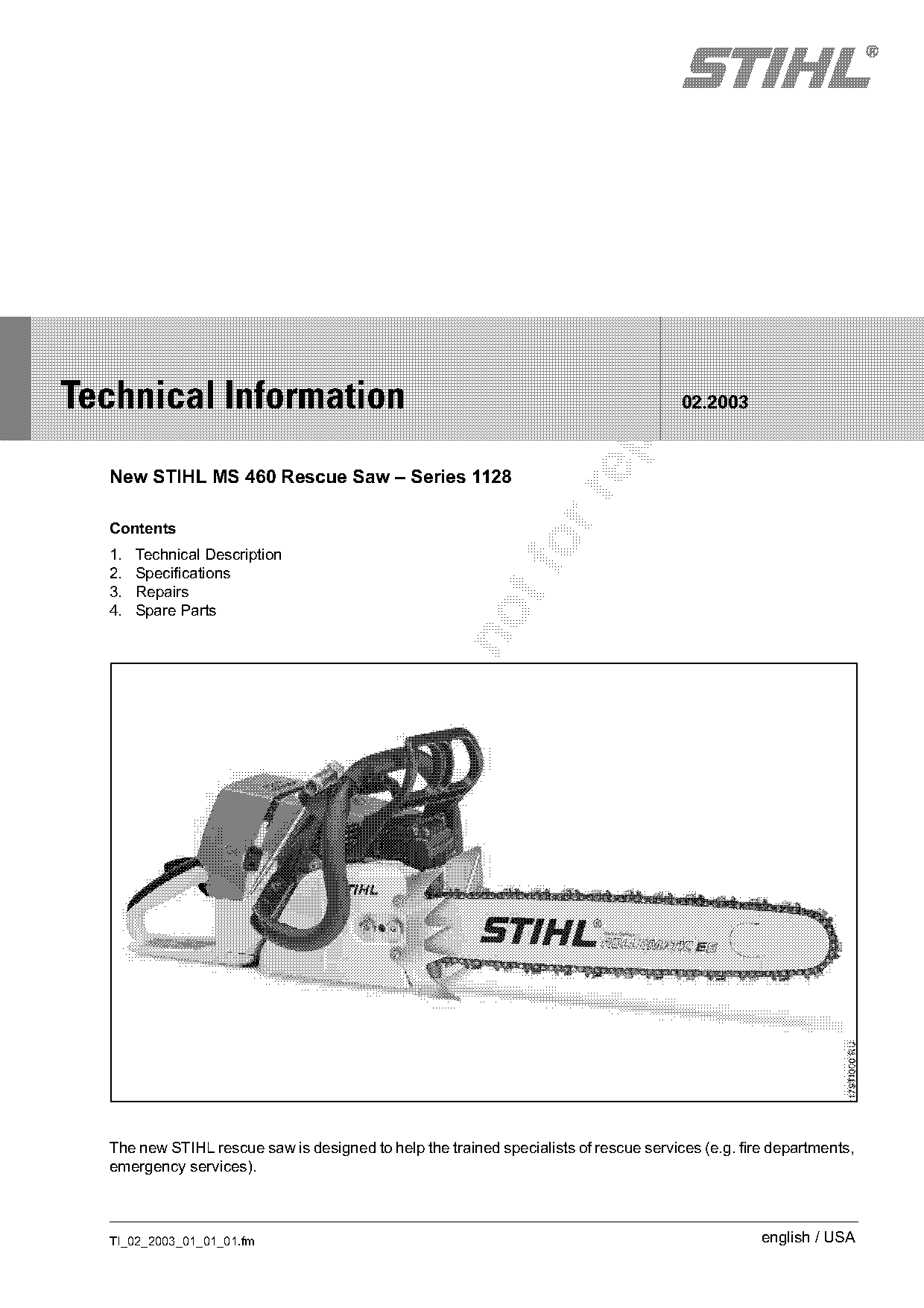
  New STIHL MS 460 Rescue Saw – Series 1128

  Contents
  1.
  2.
       Technical Description
       Specifications
  3.   Repairs
  4.   Spare Parts

  The new STIHL rescue saw is designed to help the trained specialists of rescue services (e.g. fire departments,
  emergency services).

  TI_02_2003_01_01_01.fm                                                                           english / USA
Page 2 of 6
Text of page 2 — search, copy, screen readers
Page 2                                                                                 Technical Information 02.2003

1.    Technical Description                                       1.3   Starter Grip

1.1   Cutting Attachment
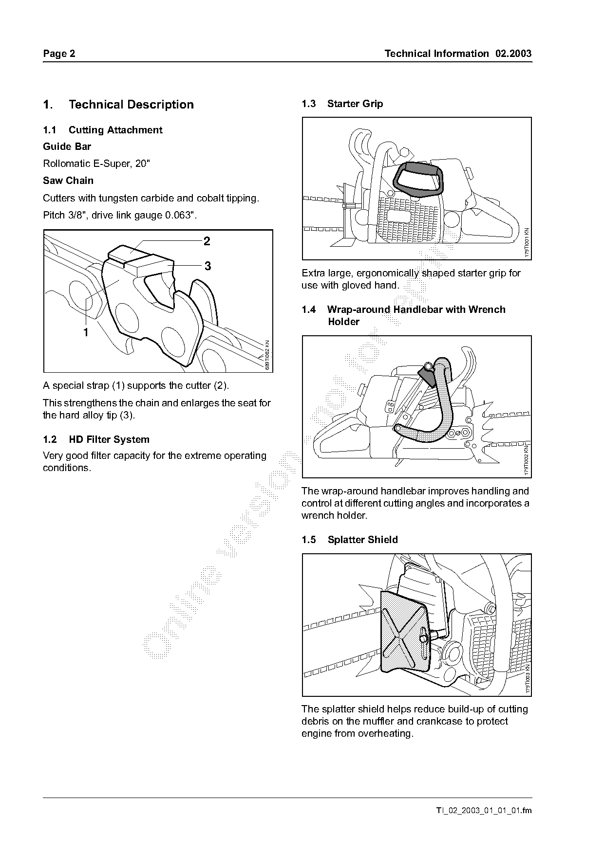
Guide Bar
Rollomatic E-Super, 20"
Saw Chain
Cutters with tungsten carbide and cobalt tipping.
Pitch 3/8", drive link gauge 0.063".

                                                                                                                        179TI001 KN
                                       2

                                       3
                                                                  Extra large, ergonomically shaped starter grip for
                                                                  use with gloved hand.

                                                                  1.4   Wrap-around Handlebar with Wrench
                                                                        Holder

         1
                                                    689TI062 KN

A special strap (1) supports the cutter (2).
This strengthens the chain and enlarges the seat for
the hard alloy tip (3).

1.2   HD Filter System

                                                                                                                       179TI002 KN
Very good filter capacity for the extreme operating

conditions.

                                                                  The wrap-around handlebar improves handling and
                                                                  control at different cutting angles and incorporates a
                                                                  wrench holder.

                                                                  1.5   Splatter Shield

                                                                                                                          179TI003 KN

                                                                  The splatter shield helps reduce build-up of cutting
                                                                  debris on the muffler and crankcase to protect
                                                                  engine from overheating.

                                                                                                 TI_02_2003_01_01_01.fm
Page 3 of 6
Text of page 3 — search, copy, screen readers
Technical Information 02.2003                                                                          Page 3

2.      Specifications                                 Chain Lubrication

Engine                                                 Oil pump:                   Fully automatic speed-
                                                                                   controlled rotary piston
STIHL single cylinder two-cycle engine                                             pump
Displacement:                 4.67 cu. in (76.5 cc)    Oil tank capacity:          0.68 US pt (0.325 l)
Bore:                         2.05 in (52.0 mm)        Weight
Stroke:                       1.57 in (40.0 mm)
                                                       (without cutting
Idle speed:                   2,500 rpm
                                                       attachment):                15.4 lbs (7.0 kg)
Ignition System

Type:                         Electronic magneto

                              ignition                 3.    Repairs
Spark plug (resistor type):   Bosch WSR 6 F,
                                                       If the chain saw is started up in the course of
                              NGK BPMR 7 A,
                                                       servicing or repair work, it is essential to observe all

Electrode gap:                0.020 in (0.5 mm)        country-specific safety regulations and the safety
Fuel System                                            precautions outlined in the instruction manual.

Carburetor: All position diaphragm carburetor
                                                       3.1   Saw Chain
Low speed screw L
(standard setting):           1/4 turn
                              (no further than stop)
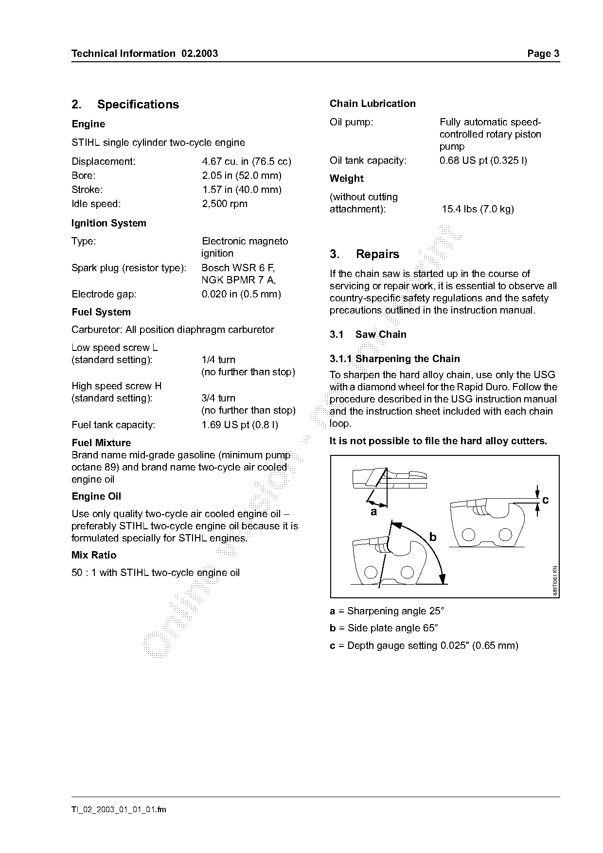
                                                       3.1.1 Sharpening the Chain
                                                       To sharpen the hard alloy chain, use only the USG
High speed screw H                                     with a diamond wheel for the Rapid Duro. Follow the
(standard setting):           3/4 turn                 procedure described in the USG instruction manual
                              (no further than stop)   and the instruction sheet included with each chain

Fuel tank capacity:           1.69 US pt (0.8 l)       loop.
Fuel Mixture                                           It is not possible to file the hard alloy cutters.
Brand name mid-grade gasoline (minimum pump

octane 89) and brand name two-cycle air cooled
engine oil

Engine Oil                                                                                                    c
Use only quality two-cycle air cooled engine oil –               a

preferably STIHL two-cycle engine oil because it is
formulated specially for STIHL engines.                                        b

Mix Ratio                                                                                                         689TI061 KN

50 : 1 with STIHL two-cycle engine oil

                                                       a = Sharpening angle 25°
                                                       b = Side plate angle 65°

                                                       c = Depth gauge setting 0.025" (0.65 mm)

TI_02_2003_01_01_01.fm
Page 4 of 6
Text of page 4 — search, copy, screen readers
Page 4                                                                                    Technical Information 02.2003

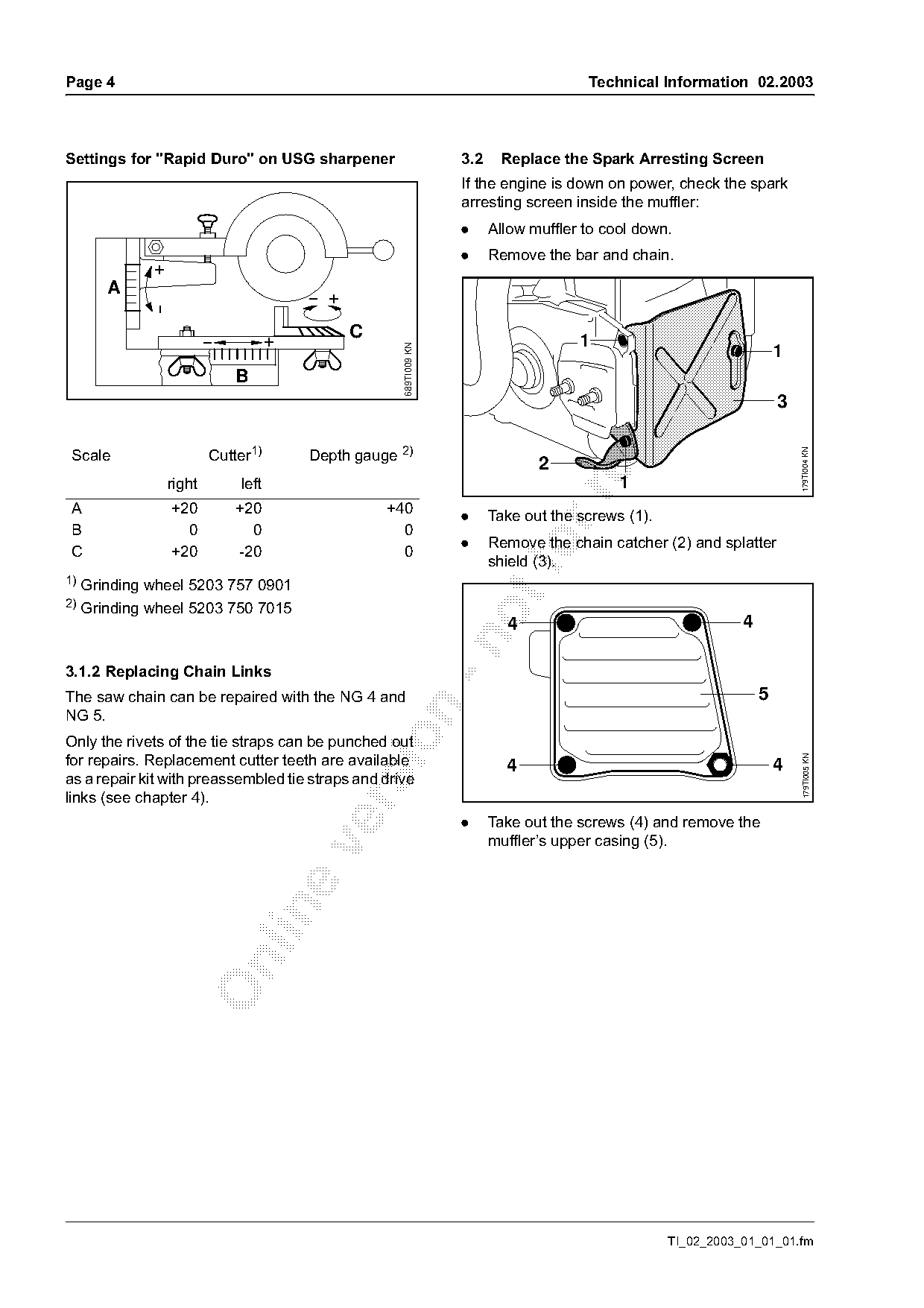
Settings for "Rapid Duro" on USG sharpener                            3.2    Replace the Spark Arresting Screen
                                                                      If the engine is down on power, check the spark
                                                                      arresting screen inside the muffler:
                                                                      .     Allow muffler to cool down.
                                                                      .     Remove the bar and chain.
              +
        A
                                              +

                                      +           C                                      1

                                                        689TI009 KN
                                                                                                                          1


 Scale                     Cutter1)       Depth gauge 2)

                                                                                                                              179TI004 KN
                                                                                   2
                   right       left                                                            1

 A                 +20         +20                    +40
                                                                      .     Take out the screws (1).
 B                   0           0                      0
                                                                      .     Remove the chain catcher (2) and splatter
 C                 +20         -20                      0
                                                                            shield (3).
1) Grinding wheel 5203 757 0901
2)
     Grinding wheel 5203 750 7015
                                                                              4                                   4

3.1.2 Replacing Chain Links
The saw chain can be repaired with the NG 4 and                                                                       5

NG 5.

Only the rivets of the tie straps can be punched out
for repairs. Replacement cutter teeth are available

                                                                                                                               179TI005 KN
                                                                              4                                           4
as a repair kit with preassembled tie straps and drive
links (see chapter 4).

                                                                      .     Take out the screws (4) and remove the
                                                                            muffler’s upper casing (5).

                                                                                                       TI_02_2003_01_01_01.fm
Page 5 of 6
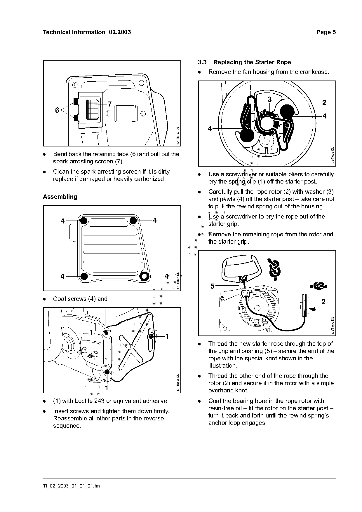
Text of page 5 — search, copy, screen readers
Technical Information 02.2003                                                                                           Page 5

                                                                      3.3       Replacing the Starter Rope
                                                                      .     Remove the fan housing from the crankcase.

                                                                                            1
                                                                                                    3                      2
                          7
    6                                                                                                     4
                                                                                                                           4
                                                                            4

                                                        179TI006 KN

                                                                                                                               179TI009 KN
.   Bend back the retaining tabs (6) and pull out the
    spark arresting screen (7).
.   Clean the spark arresting screen if it is dirty –

                                                                      .     Use a screwdriver or suitable pliers to carefully
    replace if damaged or heavily carbonized                                pry the spring clip (1) off the starter post.
                                                                      .     Carefully pull the rope rotor (2) with washer (3)

Assembling                                                                  and pawls (4) off the starter post – take care not
                                                                            to pull the rewind spring out of the housing.

        4                                   4
                                                                      .   foUse a screwdriver to pry the rope out of the
                                                                            starter grip.
                                                                      .     Remove the remaining rope from the rotor and
                                                                            the starter grip.
                                                     -n 179TI007 KN

        4                                       4


.   Coat screws (4) and
                                                                                                                          2

                                                                                                                               179TI010 KN

                  1
                                                 1
                                                                      .     Thread the new starter rope through the top of
                                                                            the grip and bushing (5) – secure the end of the

                                                                            rope with the special knot shown in the
                                                                            illustration.
                                                                      .     Thread the other end of the rope through the
                                                        179TI008 KN

                                                                            rotor (2) and secure it in the rotor with a simple
                         1                                                  overhand knot.
.   (1) with Loctite 243 or equivalent adhesive                       .     Coat the bearing bore in the rope rotor with
                                                                            resin-free oil – fit the rotor on the starter post –
.   Insert screws and tighten them down firmly.
                                                                            turn it back and forth until the rewind spring’s
    Reassemble all other parts in the reverse
                                                                            anchor loop engages.
    sequence.

TI_02_2003_01_01_01.fm
Page 6 of 6
Text of page 6 — search, copy, screen readers
Page 6                                                                                     Technical Information 02.2003

                                                                       The starter grip must locate firmly in the rope guide
                    1                                                  bushing. If the grip droops to one side, increase
                            3                                          spring tension by adding one more turn.
                                                   2                   When the starter rope is fully extended it must still
                                  4                                    be possible to rotate the rotor another half turn.
                                                   4
                                                                       If this is not possible, the spring is overtensioned
    4                                                                  and could break – take one turn of the rope off the
                                                                       rotor.
                                                                       .     Fit the fan housing on the crankcase.

                                                         179TI009 KN

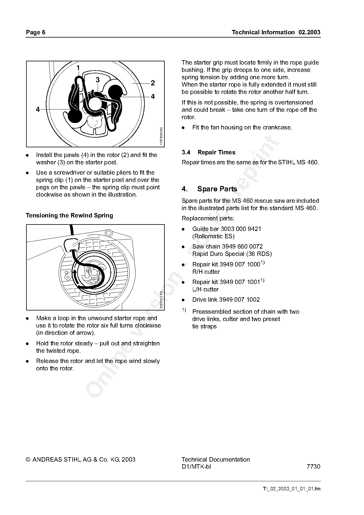
.   Install the pawls (4) in the rotor (2) and fit the                 3.4    Repair Times
    washer (3) on the starter post.                                    Repair times are the same as for the STIHL MS 460.
.   Use a screwdriver or suitable pliers to fit the

    spring clip (1) on the starter post and over the
    pegs on the pawls – the spring clip must point                     4.     Spare Parts
    clockwise as shown in the illustration.

                                                                       Spare parts for the MS 460 rescue saw are included
                                                                       in the illustrated parts list for the standard MS 460.
Tensioning the Rewind Spring                                                    fo
                                                                       Replacement parts:
                                                                       .     Guide bar 3003 000 9421
                                                                             (Rollomatic ES)
                                                                       .     Saw chain 3949 660 0072

                                                                             Rapid Duro Special (36 RDS)
                                                                       .     Repair kit 3949 007 10001)
                                                                             R/H cutter

                                                                       .     Repair kit 3949 007 10011)
                                                                             L/H cutter
                                               sio       179TI011 KN

                                                                       .     Drive link 3949 007 1002
                                                                       1)
                                                                             Preassembled section of chain with two

.   Make a loop in the unwound starter rope and                              drive links, cutter and two preset
    use it to rotate the rotor six full turns clockwise                      tie straps
    (in direction of arrow).

.   Hold the rotor steady – pull out and straighten
    the twisted rope.

.   Release the rotor and let the rope wind slowly
    onto the rotor.

© ANDREAS STIHL AG & Co. KG, 2003                                      Technical Documentation
                                                                       D1/MTK-bl                                        7730

                                                                                                        TI_02_2003_01_01_01.fm
Most of these PDFs embed fonts with a shifted character map, so the text above was recovered rather than copied — read it as a faithful but imperfect transcription, and treat the page image above each block as the authority where the two disagree — the figures exist only there, because they are vector drawings that text extraction cannot keep.