Technical Information · issue 3 of 2003
Carburetor; Impulse hose, carburetor end cover and
IssueTI 3/2003
Part changes (1)
| Was | Becomes | What the bulletin says |
|---|---|---|
| 4180 141 9000 | 4180 141 9001 | Service notes The previous spark arresting screen 4180 141 9000 The specific national safety regulations and the will be replaced by version 4180 141 9001 in the safety instructions in the owner's manual must be future. |
Full text
Page 1 of 9
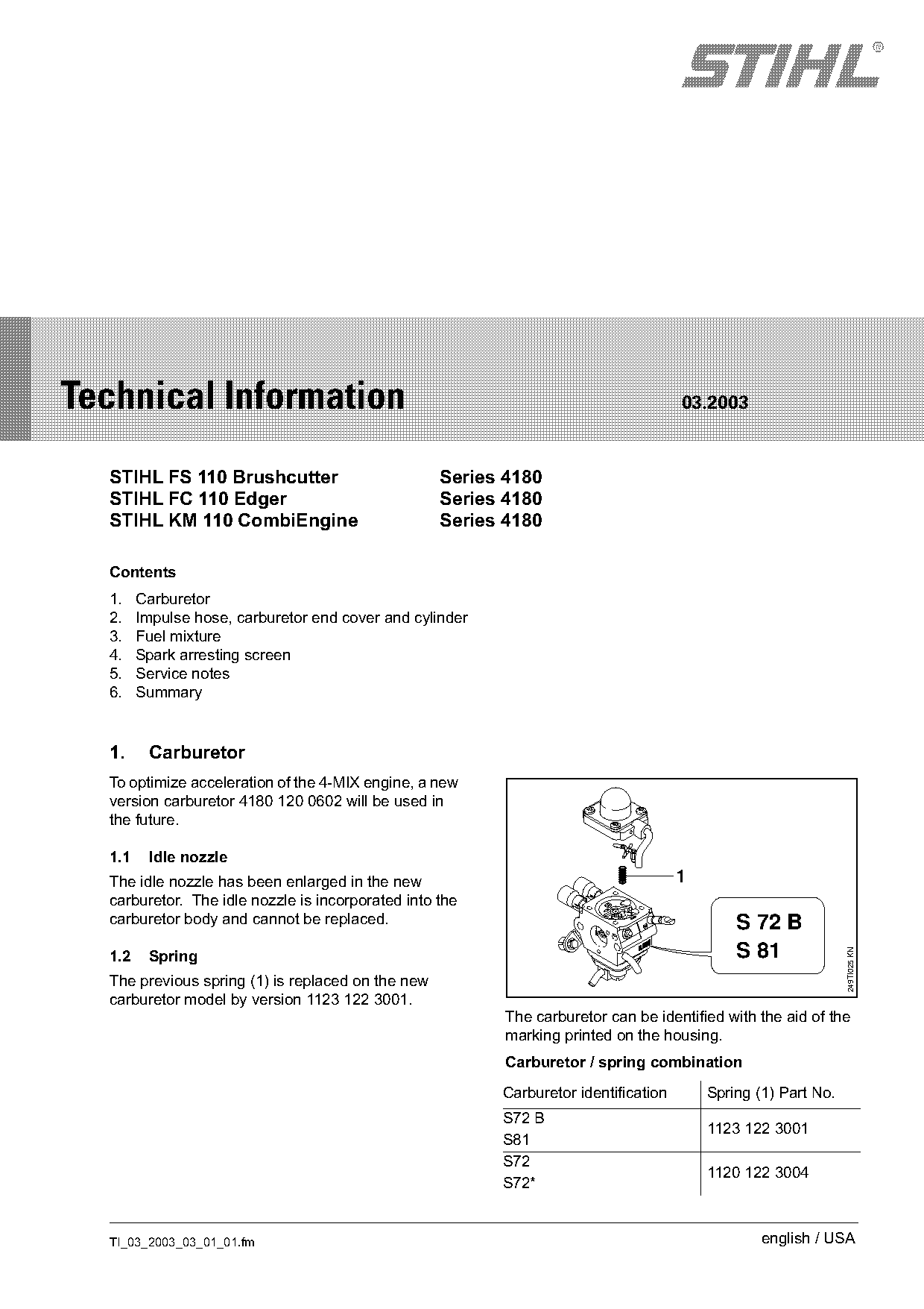
Text of page 1 — search, copy, screen readers
STIH)

Technical Information                                                                 03.2003

  STIHL FS 110 Brushcutter                         Series 4180
  STIHL FC 110 Edger                               Series 4180
  STIHL KM 110 CombiEngine                         Series 4180

  Contents
  1.    Carburetor
  2.    Impulse hose, carburetor end cover and cylinder
  3.    Fuel mixture
  4.    Spark arresting screen
  5.    Service notes
  6.    Summary

  1.     Carburetor
  To optimize acceleration of the 4-MIX engine, a new
  version carburetor 4180 120 0602 will be used in
  the future.

  1.1    Idle nozzle
  The idle nozzle has been enlarged in the new                                        1
  carburetor. The idle nozzle is incorporated into the
  carburetor body and cannot be replaced.                                                     S 72 B
                                                                                              S 81
                                                                                                                249TI025 KN

  1.2    Spring
  The previous spring (1) is replaced on the new
  carburetor model by version 1123 122 3001.
                                                          The carburetor can be identified with the aid of the
                                                          marking printed on the housing.
                                                          Carburetor / spring combination
                                                          Carburetor identification       Spring (1) Part No.
                                                          S72 B
                                                                                          1123 122 3001
                                                          S81
                                                          S72
                                                                                          1120 122 3004
                                                          S72*

  TI_03_2003_03_01_01.fm                                                                          english / USA
Page 2 of 9
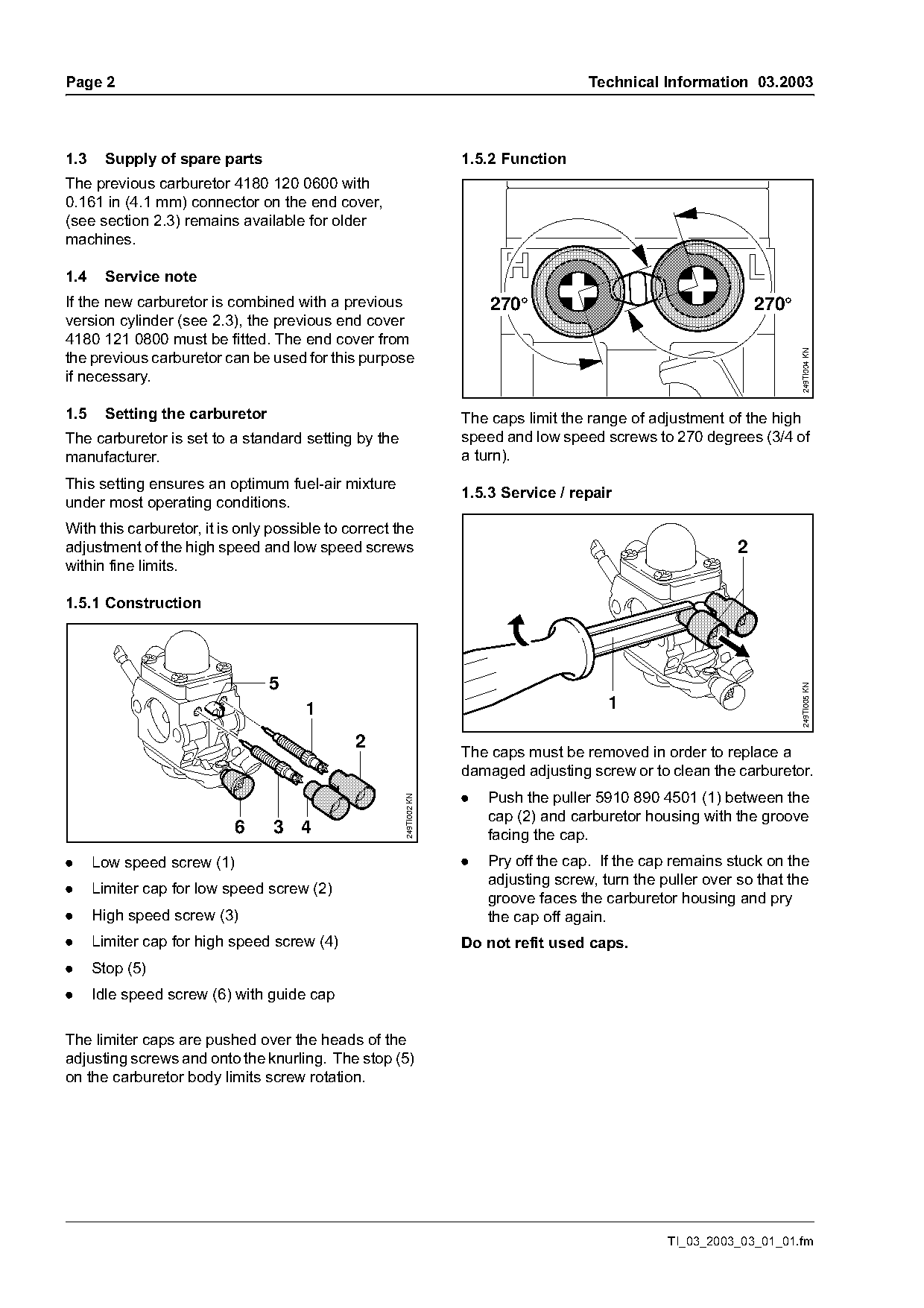
Text of page 2 — search, copy, screen readers
Page 2                                                                                 Technical Information 03.2003

1.3    Supply of spare parts                                        1.5.2 Function
The previous carburetor 4180 120 0600 with
0.161 in (4.1 mm) connector on the end cover,
(see section 2.3) remains available for older
machines.

1.4    Service note
If the new carburetor is combined with a previous                       270°                                      270°
version cylinder (see 2.3), the previous end cover
4180 121 0800 must be fitted. The end cover from

                                                                                                                         249TI004 KN
the previous carburetor can be used for this purpose
if necessary.

1.5    Setting the carburetor                                       The caps limit the range of adjustment of the high
The carburetor is set to a standard setting by the                  speed and low speed screws to 270 degrees (3/4 of
manufacturer.                                                       a turn).
This setting ensures an optimum fuel-air mixture
                                                                    1.5.3 Service / repair
under most operating conditions.
With this carburetor, it is only possible to correct the
adjustment of the high speed and low speed screws                                                             2
within fine limits.

1.5.1 Construction


                                                                                                                         249TI005 KN
                                      1                                                   1

                                              2
                                                                    The caps must be removed in order to replace a
                                                                    damaged adjusting screw or to clean the carburetor.
                                                                    .   Push the puller 5910 890 4501 (1) between the
                                                      249TI002 KN

                                                                        cap (2) and carburetor housing with the groove
                           6     3 4                                    facing the cap.
.     Low speed screw (1)                                           .   Pry off the cap. If the cap remains stuck on the
                                                                        adjusting screw, turn the puller over so that the
.     Limiter cap for low speed screw (2)
                                                                        groove faces the carburetor housing and pry
.     High speed screw (3)                                              the cap off again.
.     Limiter cap for high speed screw (4)                          Do not refit used caps.
.     Stop (5)
.     Idle speed screw (6) with guide cap

The limiter caps are pushed over the heads of the
adjusting screws and onto the knurling. The stop (5)
on the carburetor body limits screw rotation.

                                                                                                   TI_03_2003_03_01_01.fm
Page 3 of 9
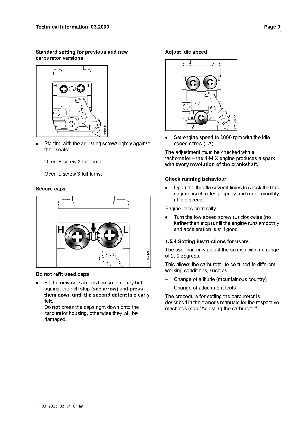
Text of page 3 — search, copy, screen readers
Technical Information 03.2003                                                                                  Page 3

Standard setting for previous and new                             Adjust idle speed
carburetor versions

                                                                          H                  L
        H                L

                                                                                                 249TI009 KN
                                                                              LA
                                 249TI006 KN

                                                                  .   Set engine speed to 2800 rpm with the idle
.   Starting with the adjusting screws lightly against                speed screw (LA).
    their seats:
                                                                  The adjustment must be checked with a
                                                                  tachometer – the 4-MIX engine produces a spark
    Open H screw 2 full turns.
                                                                  with every revolution of the crankshaft.
    Open L screw 3 full turns.
                                                                  Check running behaviour
Secure caps                                                       .   Open the throttle several times to check that the
                                                                      engine accelerates properly and runs smoothly
                                                                      at idle speed.
                                                                  Engine idles erratically
                                                                  .   Turn the low speed screw (L) clockwise (no
                                                                      further than stop) until the engine runs smoothly
            H                                  L                      and acceleration is still good.

                                                                  1.5.4 Setting instructions for users
                                                                  The user can only adjust the screws within a range
                                                    249TI007 KN

                                                                  of 270 degrees.
                                                                  This allows the carburetor to be tuned to different
                                                                  working conditions, such as:
Do not refit used caps
                                                                  –   Change of altitude (mountainous country)
.   Fit the new caps in position so that they butt
    against the rich stop (see arrow) and press                   –   Change of attachment tools
    them down until the second detent is clearly                  The procedure for setting the carburetor is
    felt.                                                         described in the owner's manuals for the respective
    Do not press the caps right down onto the                     machines (see "Adjusting the carburetor").
    carburetor housing, otherwise they will be
    damaged.

TI_03_2003_03_01_01.fm
Page 4 of 9
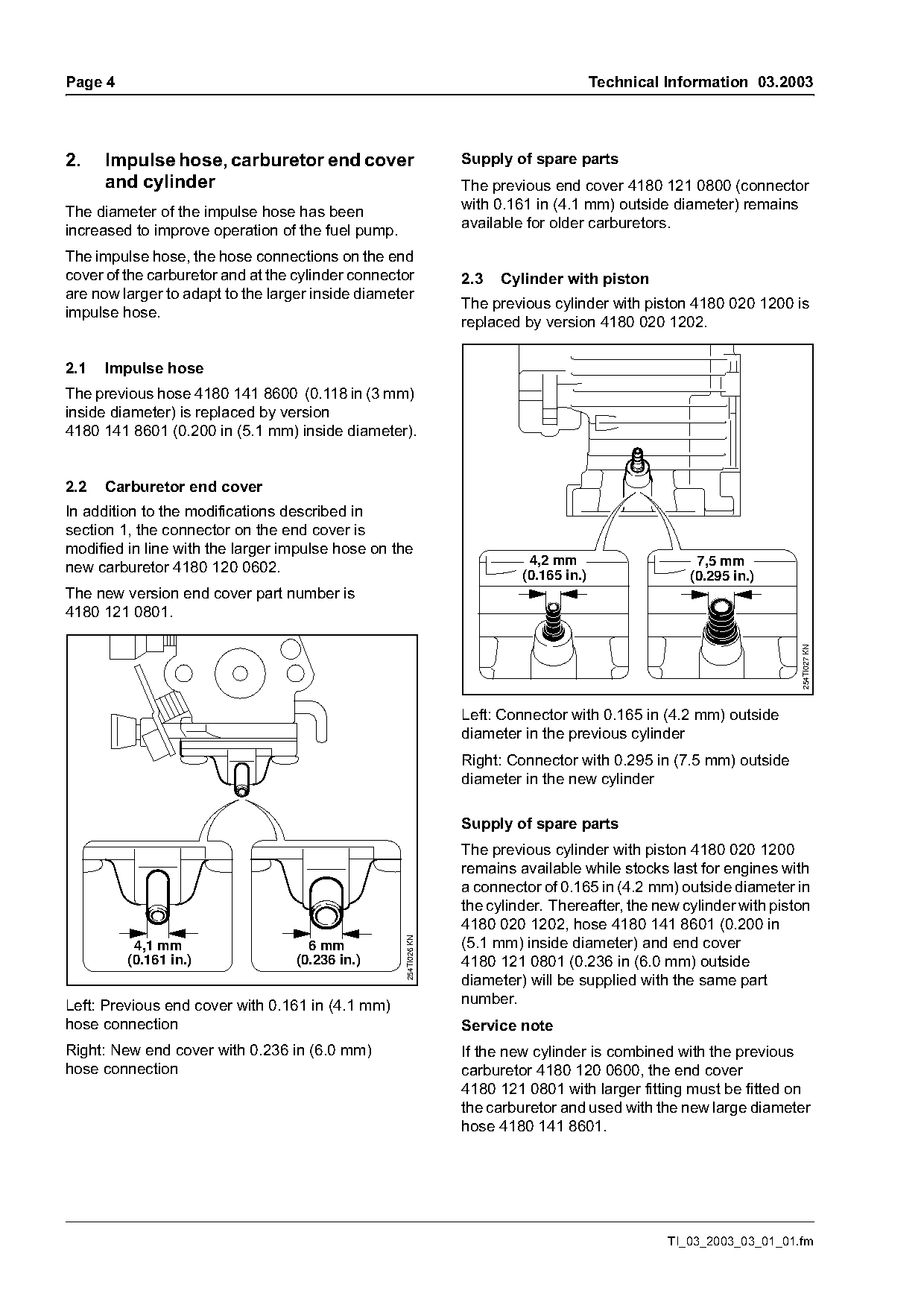
Text of page 4 — search, copy, screen readers
Page 4                                                                                  Technical Information 03.2003

2.    Impulse hose, carburetor end cover                         Supply of spare parts
      and cylinder                                               The previous end cover 4180 121 0800 (connector
The diameter of the impulse hose has been                        with 0.161 in (4.1 mm) outside diameter) remains
increased to improve operation of the fuel pump.                 available for older carburetors.

The impulse hose, the hose connections on the end
cover of the carburetor and at the cylinder connector            2.3   Cylinder with piston
are now larger to adapt to the larger inside diameter
                                                                 The previous cylinder with piston 4180 020 1200 is
impulse hose.
                                                                 replaced by version 4180 020 1202.

2.1   Impulse hose
The previous hose 4180 141 8600 (0.118 in (3 mm)
inside diameter) is replaced by version
4180 141 8601 (0.200 in (5.1 mm) inside diameter).

2.2   Carburetor end cover
In addition to the modifications described in
section 1, the connector on the end cover is
modified in line with the larger impulse hose on the
                                                                           4,2 mm                     7,5 mm
new carburetor 4180 120 0602.                                             (0.165 in.)                (0.295 in.)
The new version end cover part number is
4180 121 0801.

                                                                                                                      254TI027 KN
                                                                 Left: Connector with 0.165 in (4.2 mm) outside
                                                                 diameter in the previous cylinder
                                                                 Right: Connector with 0.295 in (7.5 mm) outside
                                                                 diameter in the new cylinder

                                                                 Supply of spare parts
                                                                 The previous cylinder with piston 4180 020 1200
                                                                 remains available while stocks last for engines with
                                                                 a connector of 0.165 in (4.2 mm) outside diameter in
                                                                 the cylinder. Thereafter, the new cylinder with piston
                                                                 4180 020 1202, hose 4180 141 8601 (0.200 in
                                                                 (5.1 mm) inside diameter) and end cover
                                                   254TI026 KN

          4,1 mm                     6 mm
         (0.161 in.)               (0.236 in.)                   4180 121 0801 (0.236 in (6.0 mm) outside
                                                                 diameter) will be supplied with the same part
Left: Previous end cover with 0.161 in (4.1 mm)                  number.
hose connection                                                  Service note
Right: New end cover with 0.236 in (6.0 mm)                      If the new cylinder is combined with the previous
hose connection                                                  carburetor 4180 120 0600, the end cover
                                                                 4180 121 0801 with larger fitting must be fitted on
                                                                 the carburetor and used with the new large diameter
                                                                 hose 4180 141 8601.

                                                                                                  TI_03_2003_03_01_01.fm
Page 5 of 9
Text of page 5 — search, copy, screen readers
Technical Information 03.2003                                                                                     Page 5

3.     Fuel mixture
Use of two-stroke engine oil with high viscosity and
an oil rich mixing ratio can lead to poor acceleration,
loss of performance, erratic running and engine
stoppage in engines with an impulse hose with
0.118 in (3.0 mm) inside diameter.
                                                                              7
Unsuitable oils may impair operation of the fuel
pump – STIHL recommends high-quality two-stroke
engine oil with the classification ISO-L-EGD –

                                                                                                                           249TI030 KN
STIHL Low Smoke Engine Oil should ideally be
used as it is formulated for STIHL engines.
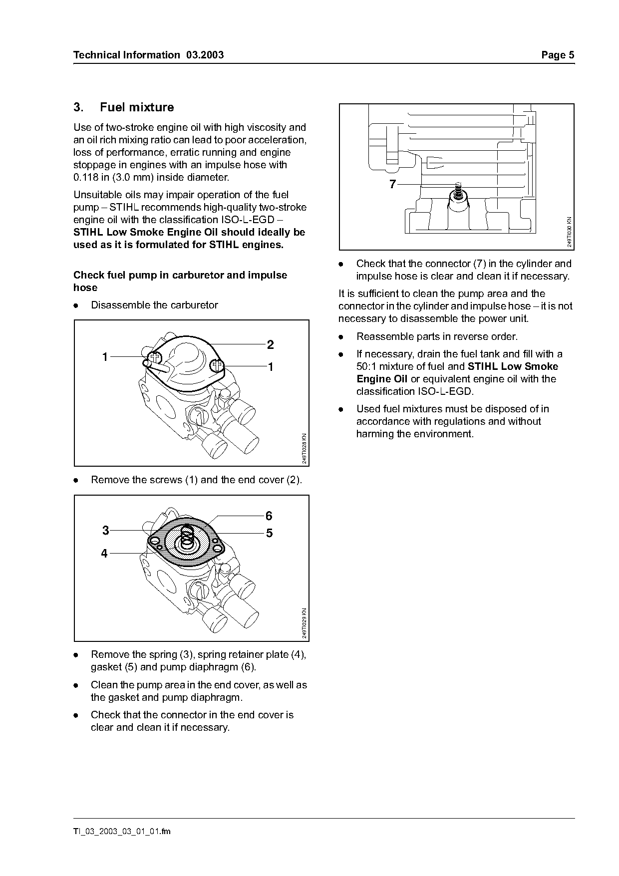
                                                                   .   Check that the connector (7) in the cylinder and
Check fuel pump in carburetor and impulse                              impulse hose is clear and clean it if necessary.
hose
                                                                   It is sufficient to clean the pump area and the
.    Disassemble the carburetor                                    connector in the cylinder and impulse hose – it is not
                                                                   necessary to disassemble the power unit.
                                                                   .   Reassemble parts in reverse order.
                                             2
       1                                                           .   If necessary, drain the fuel tank and fill with a
                                             1                         50:1 mixture of fuel and STIHL Low Smoke
                                                                       Engine Oil or equivalent engine oil with the
                                                                       classification ISO-L-EGD.
                                                                   .   Used fuel mixtures must be disposed of in
                                                                       accordance with regulations and without
                                                                       harming the environment.
                                                     249TI028 KN

.    Remove the screws (1) and the end cover (2).

                                             6
       3                                     5
       4
                                                     249TI029 KN

.    Remove the spring (3), spring retainer plate (4),
     gasket (5) and pump diaphragm (6).
.    Clean the pump area in the end cover, as well as
     the gasket and pump diaphragm.
.    Check that the connector in the end cover is
     clear and clean it if necessary.

TI_03_2003_03_01_01.fm
Page 6 of 9
Text of page 6 — search, copy, screen readers
Page 6                                                                                    Technical Information 03.2003

4.   Spark arresting screen                                       5.       Service notes
The previous spark arresting screen 4180 141 9000                 The specific national safety regulations and the
will be replaced by version 4180 141 9001 in the                  safety instructions in the owner's manual must be
future. The new spark arresting screen has a semi-                observed when the machine is started.
circular stepped recess around the fixing screw.
At the same time, the previous retaining lug on the               5.1      Accelerator pump
muffler is replaced by a cylindrical countersink.


                                                                            2                          a
                                                                       1                                              3
                                                                                                  9
                                                                                              8

                                                                                                                            249TI010 KN
                                                                                          7
                                                                                      6
                                                                                  5
                                                    249TI017 KN

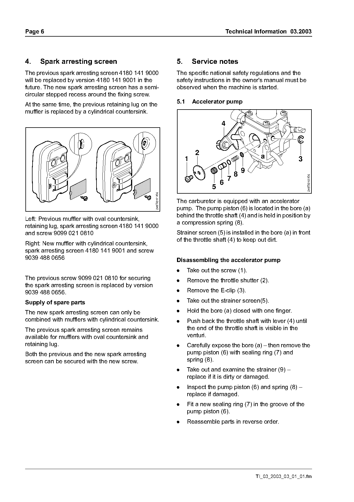
                                                                  The carburetor is equipped with an accelerator
                                                                  pump. The pump piston (6) is located in the bore (a)
                                                                  behind the throttle shaft (4) and is held in position by
Left: Previous muffler with oval countersink,
                                                                  a compression spring (8).
retaining lug, spark arresting screen 4180 141 9000
and screw 9099 021 0810                                           Strainer screen (5) is installed in the bore (a) in front
                                                                  of the throttle shaft (4) to keep out dirt.
Right: New muffler with cylindrical countersink,
spark arresting screen 4180 141 9001 and screw
9039 488 0656                                                     Disassembling the accelerator pump
                                                                  .     Take out the screw (1).
The previous screw 9099 021 0810 for securing                     .     Remove the throttle shutter (2).
the spark arresting screen is replaced by version
9039 488 0656.                                                    .     Remove the E-clip (3).

Supply of spare parts                                             .     Take out the strainer screen(5).

The new spark arresting screen can only be                        .     Hold the bore (a) closed with one finger.
combined with mufflers with cylindrical countersink.              .     Push back the throttle shaft with lever (4) until
The previous spark arresting screen remains                             the end of the throttle shaft is visible in the
available for mufflers with oval countersink and                        venturi.
retaining lug.                                                    .     Carefully expose the bore (a) – then remove the
Both the previous and the new spark arresting                           pump piston (6) with sealing ring (7) and
screen can be secured with the new screw.                               spring (8).
                                                                  .     Take out and examine the strainer (9) –
                                                                        replace if it is dirty or damaged.
                                                                  .     Inspect the pump piston (6) and spring (8) –
                                                                        replace if damaged.
                                                                  .     Fit a new sealing ring (7) in the groove of the
                                                                        pump piston (6).
                                                                  .     Reassemble parts in reverse order.

                                                                                                      TI_03_2003_03_01_01.fm
Page 7 of 9
Text of page 7 — search, copy, screen readers
Technical Information 03.2003                                                                                       Page 7

5.2     Power unit                                                    5.2.2 Leakage test
Check the compression pressure and absence of                         Defective crankshaft seals and gaskets or cracks in
leaks in the power unit in order to locate any faults                 castings cause leaks. Such faults allow
in the power unit.                                                    supplementary air to enter the engine and change
                                                                      the fuel-oil-air mixture.
The air filter, spark arresting screen, fuel supply,
carburetor and ignition system must be checked                        This can upset the lubricating process or cause it to
before attempting to locate faults in the power unit.                 fail altogether.
                                                                      The engine can be checked for leaks with the
5.2.1 Check compression pressure
                                                                      carburetor and crankcase tester and the vacuum
.     Pull the boot off the spark plug and then                       pump.
      unscrew the spark plug.
                                                                      Preparations
                                                                      .   Move the slide control to STOP–$.
                                                                      .   Remove the shroud.

                                   1                                  .   Remove the filter cover and air filter.
                                                                      .   Remove the filter housing and pull off the
                                                                          gasket.
                                                                      .   To release tank pressure, open the tank cap and
                                                                          then close it again.
                                                        249TI013 KN

                                                                      .   Disconnect the fuel hoses and the impulse hose
                                                                          from the carburetor.
                                                                      .   Disconnect the throttle cable.
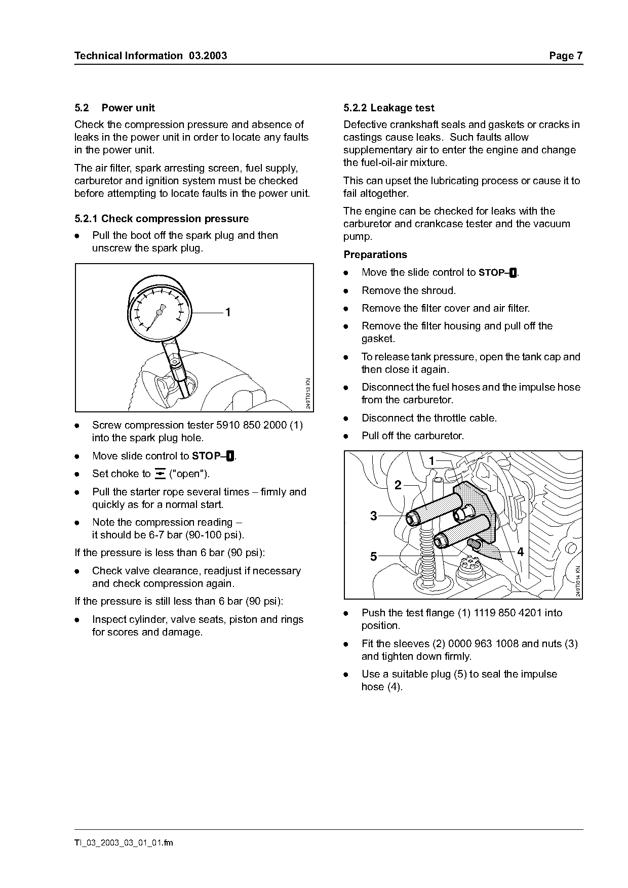
.     Screw compression tester 5910 850 2000 (1)
      into the spark plug hole.                                       .   Pull off the carburetor.
.     Move slide control to STOP–$.
                                                                                         1
.     Set choke to e ("open").
.     Pull the starter rope several times – firmly and
                                                                                 2
      quickly as for a normal start.
.     Note the compression reading –
                                                                            3
      it should be 6-7 bar (90-100 psi).
If the pressure is less than 6 bar (90 psi):                                5                                4
.     Check valve clearance, readjust if necessary                                                                        249TI014 KN
      and check compression again.
If the pressure is still less than 6 bar (90 psi):
                                                                      .   Push the test flange (1) 1119 850 4201 into
.     Inspect cylinder, valve seats, piston and rings
                                                                          position.
      for scores and damage.
                                                                      .   Fit the sleeves (2) 0000 963 1008 and nuts (3)
                                                                          and tighten down firmly.
                                                                      .   Use a suitable plug (5) to seal the impulse
                                                                          hose (4).

TI_03_2003_03_01_01.fm
Page 8 of 9
Text of page 8 — search, copy, screen readers
Page 8                                                                                Technical Information 03.2003

                                                                   Vacuum test
                                 1                                 Crankshaft seals tend to fail when subjected to a
                                                                   vacuum, i.e. the sealing lip lifts away from the
                                                                   crankshaft during the piston's induction stroke
                                                                   because there is no internal counterpressure vs.
                                                                   atmospheric pressure.

                                                    249TI015 KN
.   Loosen the muffler mounting screws.
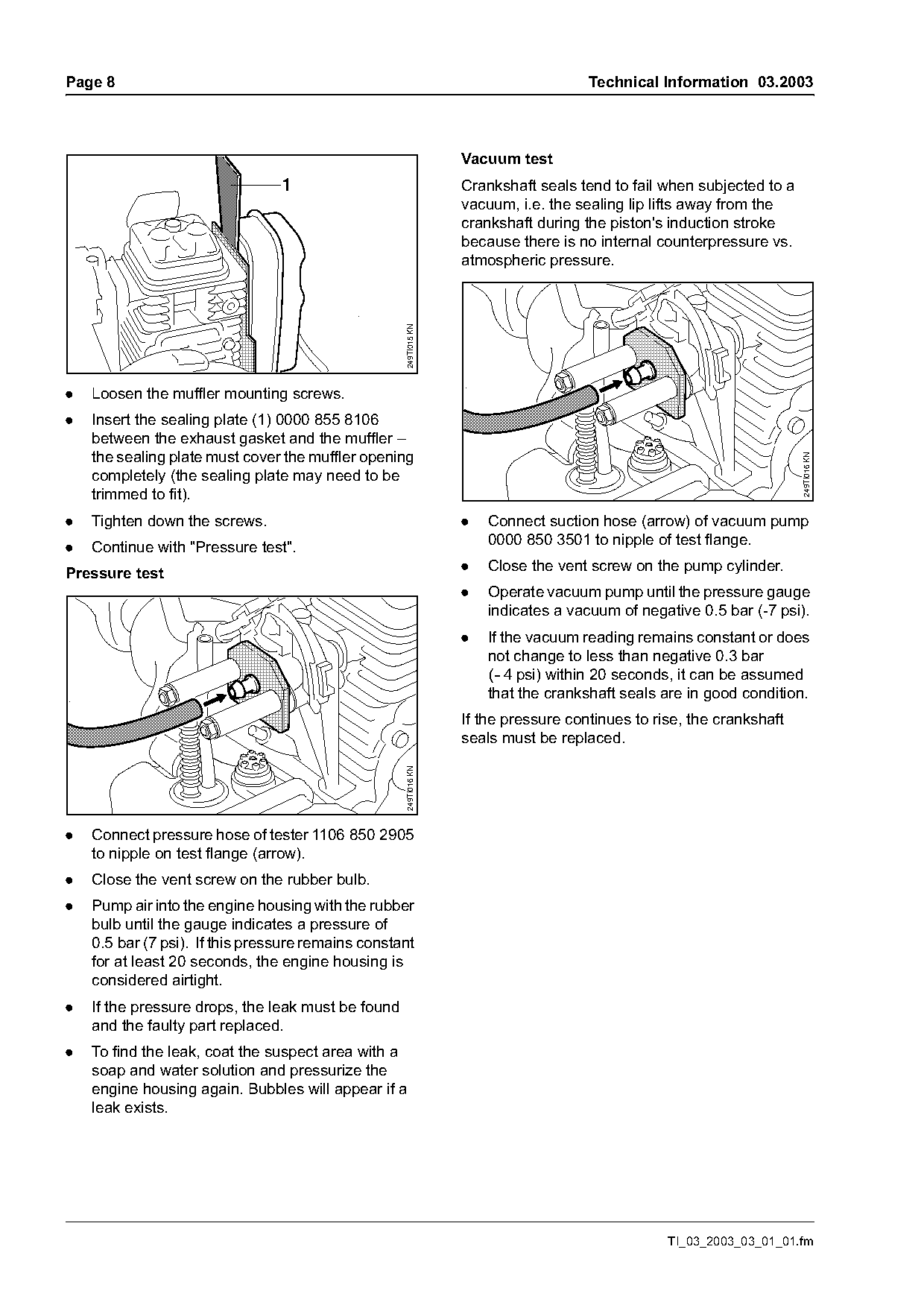
.   Insert the sealing plate (1) 0000 855 8106
    between the exhaust gasket and the muffler –
    the sealing plate must cover the muffler opening

                                                                                                                       249TI016 KN
    completely (the sealing plate may need to be
    trimmed to fit).
.   Tighten down the screws.                                       .   Connect suction hose (arrow) of vacuum pump
                                                                       0000 850 3501 to nipple of test flange.
.   Continue with "Pressure test".
Pressure test                                                      .   Close the vent screw on the pump cylinder.
                                                                   .   Operate vacuum pump until the pressure gauge
                                                                       indicates a vacuum of negative 0.5 bar (-7 psi).
                                                                   .   If the vacuum reading remains constant or does
                                                                       not change to less than negative 0.3 bar
                                                                       (- 4 psi) within 20 seconds, it can be assumed
                                                                       that the crankshaft seals are in good condition.
                                                                   If the pressure continues to rise, the crankshaft
                                                                   seals must be replaced.
                                                     249TI016 KN

.   Connect pressure hose of tester 1106 850 2905
    to nipple on test flange (arrow).
.   Close the vent screw on the rubber bulb.
.   Pump air into the engine housing with the rubber
    bulb until the gauge indicates a pressure of
    0.5 bar (7 psi). If this pressure remains constant
    for at least 20 seconds, the engine housing is
    considered airtight.
.   If the pressure drops, the leak must be found
    and the faulty part replaced.
.   To find the leak, coat the suspect area with a
    soap and water solution and pressurize the
    engine housing again. Bubbles will appear if a
    leak exists.

                                                                                                  TI_03_2003_03_01_01.fm
Page 9 of 9
Text of page 9 — search, copy, screen readers
Technical Information 03.2003                                                                Page 9

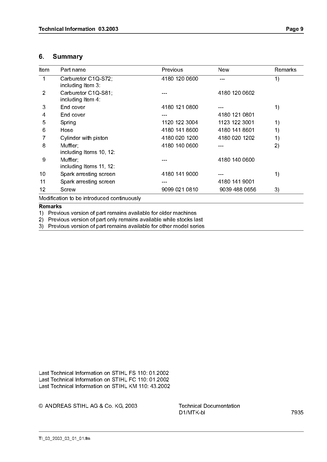
6.     Summary
Item     Part name                                Previous             New              Remarks
 1       Carburetor C1Q-S72;                      4180 120 0600         ---             1)
         including Item 3:
 2       Carburetor C1Q-S81;                      ---                  4180 120 0602
         including Item 4:
 3       End cover                                4180 121 0800        ---              1)
 4       End cover                                ---                  4180 121 0801
 5       Spring                                   1120 122 3004        1123 122 3001    1)
 6       Hose                                     4180 141 8600        4180 141 8601    1)
 7       Cylinder with piston                     4180 020 1200        4180 020 1202    1)
 8       Muffler;                                 4180 140 0600        ---              2)
         including Items 10, 12:
 9       Muffler;                                 ---                  4180 140 0600
         including Items 11, 12:
10       Spark arresting screen                   4180 141 9000        ---              1)
11       Spark arresting screen                   ---                  4180 141 9001
12       Screw                                    9099 021 0810         9039 488 0656   3)
Modification to be introduced continuously
Remarks
1) Previous version of part remains available for older machines
2) Previous version of part only remains available while stocks last
3) Previous version of part remains available for other model series

Last Technical Information on STIHL FS 110: 01.2002
Last Technical Information on STIHL FC 110: 01.2002
Last Technical Information on STIHL KM 110: 43.2002

© ANDREAS STIHL AG & Co. KG, 2003                        Technical Documentation
                                                         D1/MTK-bl                            7935

TI_03_2003_03_01_01.fm
Most of these PDFs embed fonts with a shifted character map, so the text above was recovered rather than copied — read it as a faithful but imperfect transcription, and treat the page image above each block as the authority where the two disagree — the figures exist only there, because they are vector drawings that text extraction cannot keep.