Technical Information · issue 5 of 2003
Control Handle and Throttle Cable (FS 400, 450, FR
Model FS 350 Clearing Saw – Series 4134
IssueTI 5/2003
Part changes (1)
| Was | Becomes | What the bulletin says |
|---|---|---|
| 4134 180 6701 | 4134 180 6702 | retainer 4134 180 6701 and lower retainer 4134 182 2105) will be replaced by the new retainer 4134 180 6702 and lower retainer 4134 182 2104. |
Full text
Page 1 of 10
Text of page 1 — search, copy, screen readers
STIH)

Technical Information

                                                                                05.2003

  Model FS 350 Clearing Saw                                – Series 4134

  Model FS 450 Clearing Saw                                – Series 4128

  Contents
  1.   Control Handle and Throttle Cable (FS 450)
  2.   Gearhead (FS 350, FS 450)
  3.   Drive Tube (FS 350)
  4.   Rewind Starter, Fan Housing, Shroud (FS 450)

  5.   Clutch (FS 350, FS 450)

  1.    Control Handle and Throttle Cable

        (FS 450)
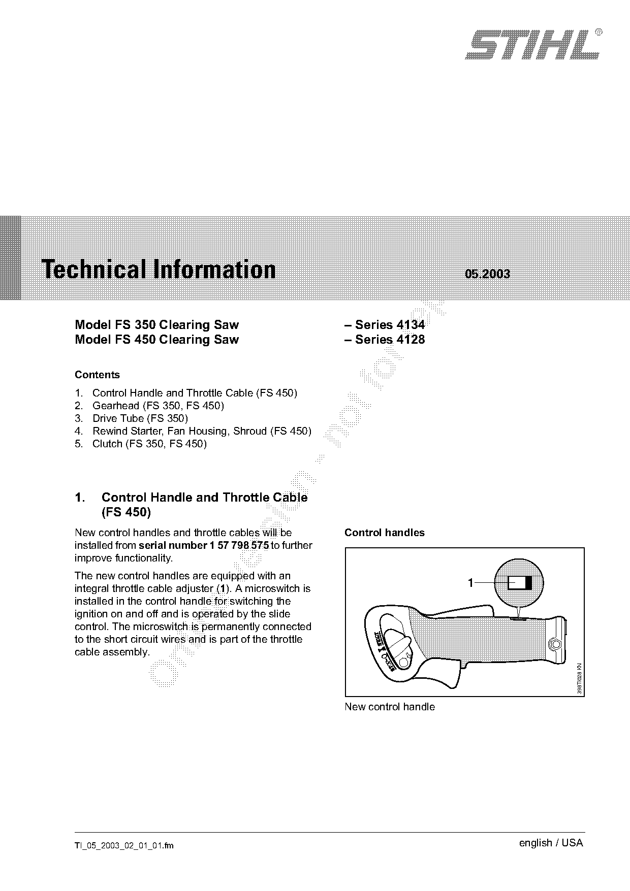
  New control handles and throttle cables will be          Control handles
  installed from serial number 1 57 798 575 to further

  improve functionality.
  The new control handles are equipped with an

  integral throttle cable adjuster (1). A microswitch is
                                                                                1
  installed in the control handle for switching the
  ignition on and off and is operated by the slide

  control. The microswitch is permanently connected
  to the short circuit wires and is part of the throttle
  cable assembly.

                                                                                                     398TI028 KN

                                                           New control handle

  TI_05_2003_02_01_01.fm                                                                  english / USA
Page 2 of 10
Text of page 2 — search, copy, screen readers
Page 2                                                                                 Technical Information 05.2003

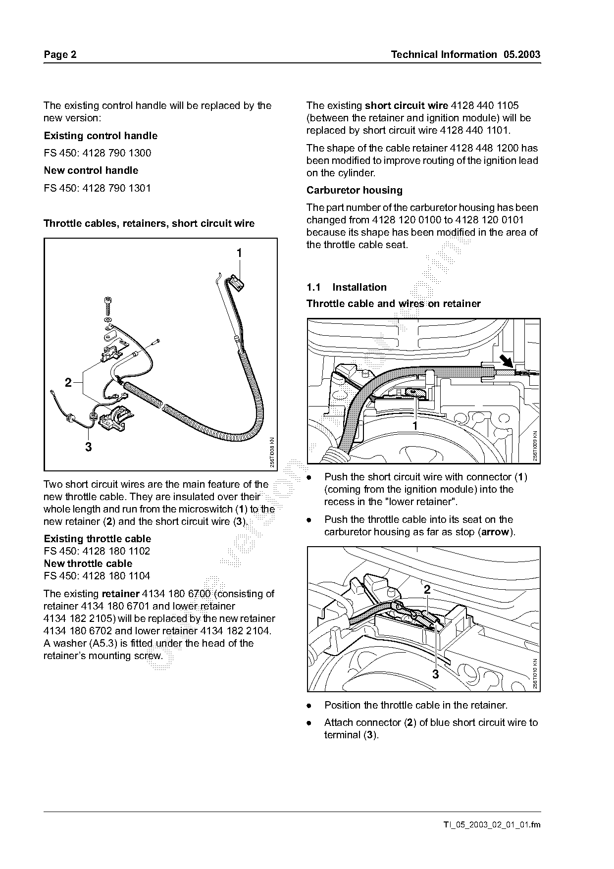
The existing control handle will be replaced by the             The existing short circuit wire 4128 440 1105
new version:                                                    (between the retainer and ignition module) will be
                                                                replaced by short circuit wire 4128 440 1101.
Existing control handle
FS 450: 4128 790 1300                                           The shape of the cable retainer 4128 448 1200 has
                                                                been modified to improve routing of the ignition lead
New control handle                                              on the cylinder.
FS 450: 4128 790 1301                                           Carburetor housing
                                                                The part number of the carburetor housing has been
Throttle cables, retainers, short circuit wire                  changed from 4128 120 0100 to 4128 120 0101
                                                                because its shape has been modified in the area of

                                                                the throttle cable seat.
                                           1

                                                                1.1     Installation

                                                                Throttle cable and wires on retainer


                                                                                                                           256TI009 KN
                                                  256TI008 KN


                                                                .     Push the short circuit wire with connector (1)
Two short circuit wires are the main feature of the
                                                                      (coming from the ignition module) into the

new throttle cable. They are insulated over their
                                                                      recess in the "lower retainer".
whole length and run from the microswitch (1) to the
new retainer (2) and the short circuit wire (3).                .     Push the throttle cable into its seat on the
                                                                      carburetor housing as far as stop (arrow).

Existing throttle cable
FS 450: 4128 180 1102

New throttle cable
FS 450: 4128 180 1104
The existing retainer 4134 180 6700 (consisting of                                             2

retainer 4134 180 6701 and lower retainer
4134 182 2105) will be replaced by the new retainer
4134 180 6702 and lower retainer 4134 182 2104.

A washer (A5.3) is fitted under the head of the
retainer’s mounting screw.
                                                                                                                           256TI010 KN


                                                                .     Position the throttle cable in the retainer.
                                                                .     Attach connector (2) of blue short circuit wire to
                                                                      terminal (3).

                                                                                                       TI_05_2003_02_01_01.fm
Page 3 of 10
Text of page 3 — search, copy, screen readers
Technical Information 05.2003                                                                                            Page 3

                                                                       Slide and throttle cable in control handle
                  4

                                                                                                   7 8

                                                        256TI011 KN

                                                                                                                               398TI037 KN
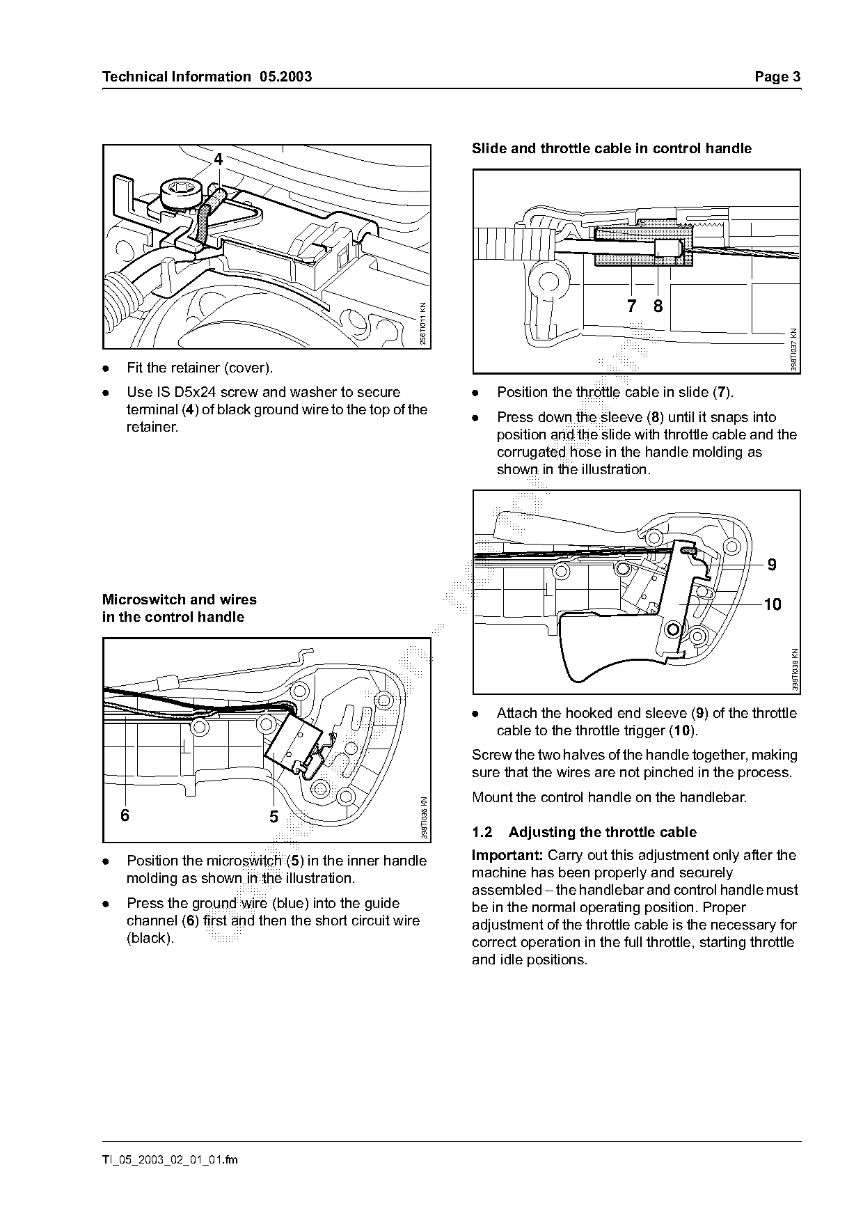
.   Fit the retainer (cover).
.   Use IS D5x24 screw and washer to secure                            .     Position the throttle cable in slide (7).
    terminal (4) of black ground wire to the top of the

                                                                       .     Press down the sleeve (8) until it snaps into
    retainer.
                                                                             position and the slide with throttle cable and the
                                                                             corrugated hose in the handle molding as

                                                                             shown in the illustration.


Microswitch and wires

                                                                                                                          10
in the control handle

                                                                                                                                 398TI038 KN

                                                                       .     Attach the hooked end sleeve (9) of the throttle
                                                                             cable to the throttle trigger (10).

                                                                       Screw the two halves of the handle together, making
                                                                       sure that the wires are not pinched in the process.

                                                                       Mount the control handle on the handlebar.
                                                         398TI036 KN

    6                       5
                                                                       1.2     Adjusting the throttle cable

.   Position the microswitch (5) in the inner handle                   Important: Carry out this adjustment only after the
    molding as shown in the illustration.                              machine has been properly and securely
                                                                       assembled – the handlebar and control handle must

.   Press the ground wire (blue) into the guide                        be in the normal operating position. Proper
    channel (6) first and then the short circuit wire                  adjustment of the throttle cable is the necessary for
    (black).                                                           correct operation in the full throttle, starting throttle
                                                                       and idle positions.

TI_05_2003_02_01_01.fm
Page 4 of 10
Text of page 4 — search, copy, screen readers
Page 4                                                                                   Technical Information 05.2003


                                                           398TI039 KN

.       Use a screwdriver to push the slide (11) in the
        direction of the arrow to the end of the slot.
.       Hold down the interlock lever and squeeze the

        trigger to the full throttle position – the throttle
        cable is now correctly adjusted.

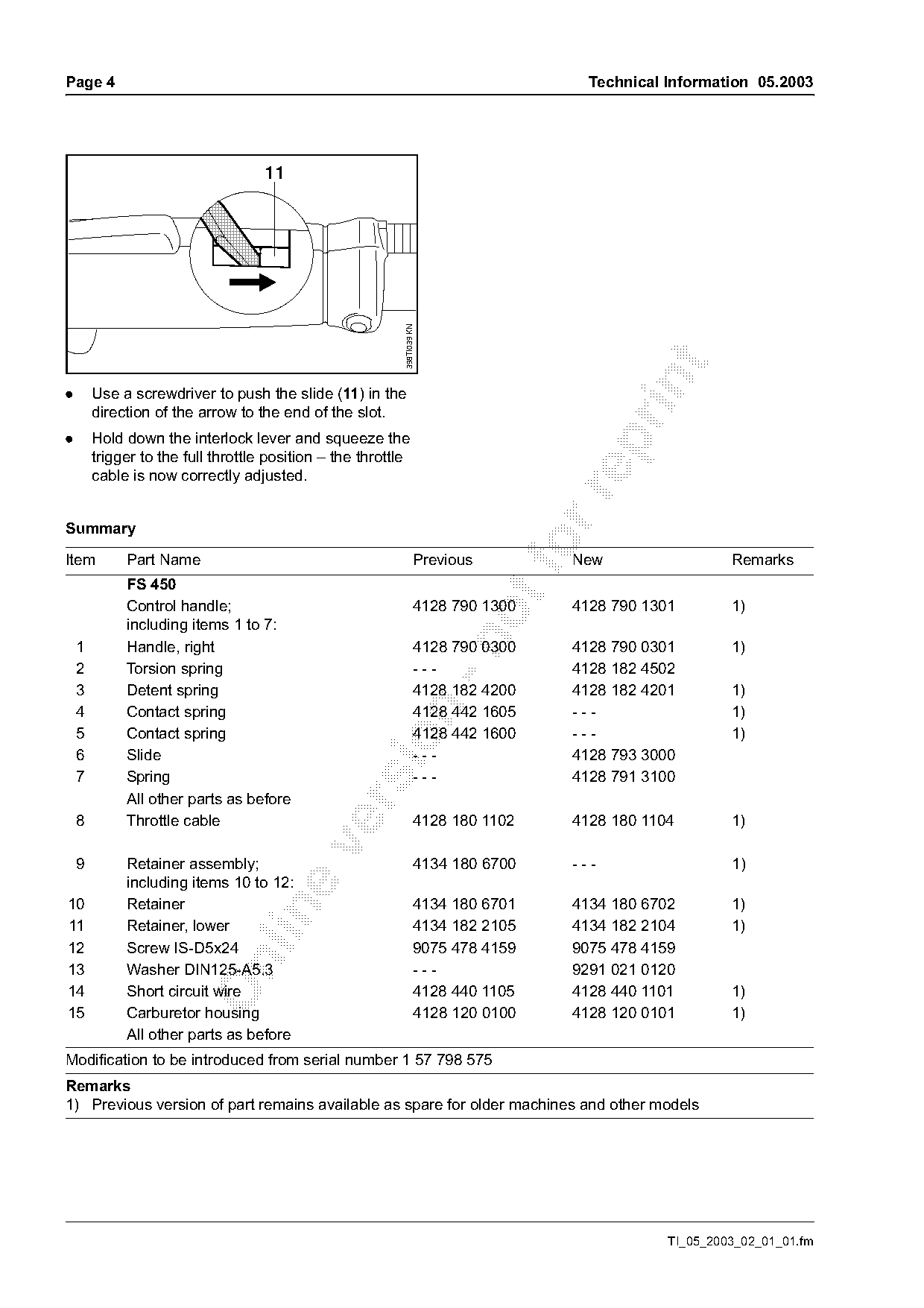
Summary

Item         Part Name                                              Previous
                                                                                     New                    Remarks
             FS 450
             Control handle;                                        4128 790 1300    4128 790 1301          1)
             including items 1 to 7:

    1        Handle, right                                          4128 790 0300    4128 790 0301          1)
    2        Torsion spring                                         ---              4128 182 4502
    3        Detent spring                                          4128 182 4200    4128 182 4201          1)

    4        Contact spring                                         4128 442 1605    ---                    1)
    5        Contact spring                                         4128 442 1600    ---                    1)

    6        Slide                                                  ---              4128 793 3000
    7        Spring                                                 ---              4128 791 3100
             All other parts as before

    8        Throttle cable                                         4128 180 1102    4128 180 1104          1)

    9        Retainer assembly;                                     4134 180 6700    ---                    1)
             including items 10 to 12:
10           Retainer                                               4134 180 6701    4134 180 6702          1)

11           Retainer, lower                                        4134 182 2105    4134 182 2104          1)
12           Screw IS-D5x24                                         9075 478 4159    9075 478 4159

13           Washer DIN125-A5.3                                     ---              9291 021 0120
14           Short circuit wire                                     4128 440 1105    4128 440 1101          1)
15           Carburetor housing                                     4128 120 0100    4128 120 0101          1)
             All other parts as before
Modification to be introduced from serial number 1 57 798 575
Remarks
1) Previous version of part remains available as spare for older machines and other models

                                                                                                   TI_05_2003_02_01_01.fm
Page 5 of 10
Text of page 5 — search, copy, screen readers
Technical Information 05.2003                                                                                  Page 5

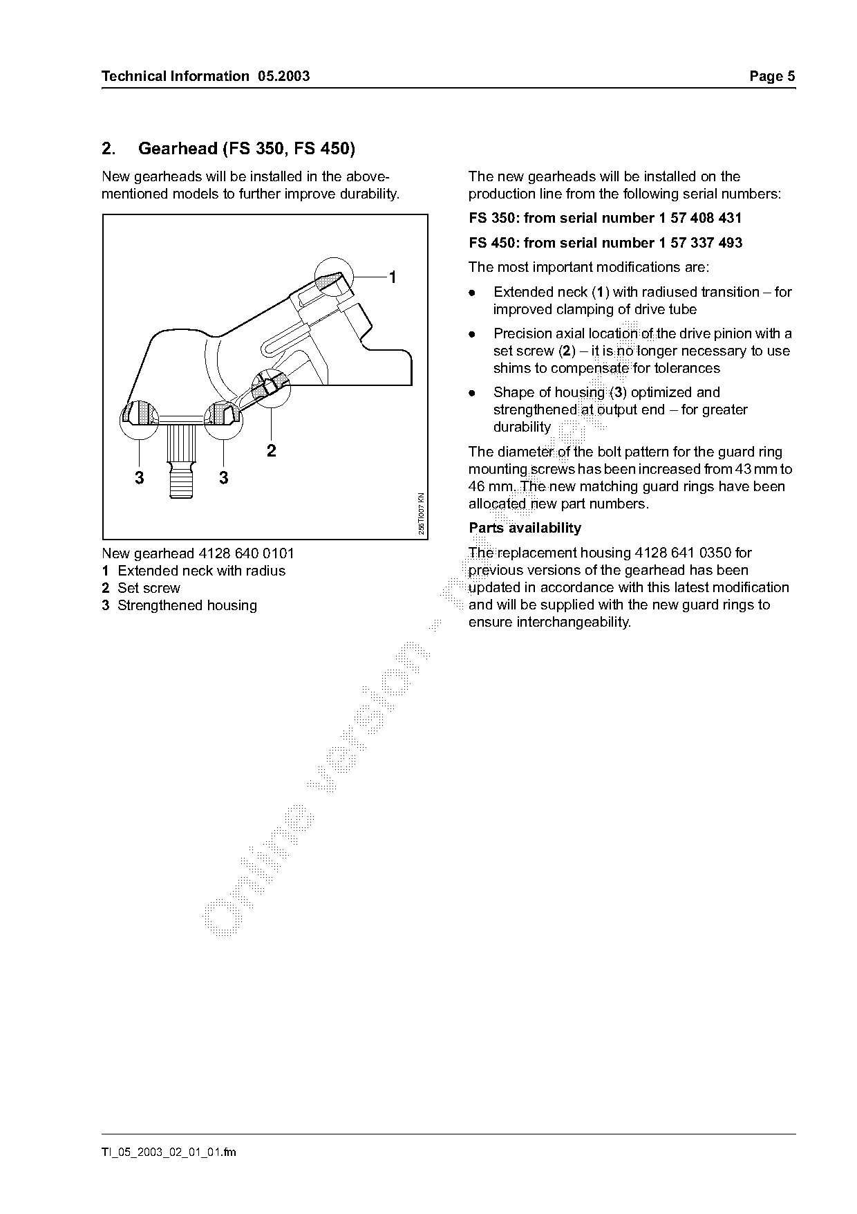
2.   Gearhead (FS 350, FS 450)
New gearheads will be installed in the above-                   The new gearheads will be installed on the
mentioned models to further improve durability.                 production line from the following serial numbers:
                                                                FS 350: from serial number 1 57 408 431
                                                                FS 450: from serial number 1 57 337 493
                                                                The most important modifications are:
                                             1
                                                                .   Extended neck (1) with radiused transition – for
                                                                    improved clamping of drive tube
                                                                .   Precision axial location of the drive pinion with a

                                                                    set screw (2) – it is no longer necessary to use

                                                                    shims to compensate for tolerances
                                                                .   Shape of housing (3) optimized and
                                                                    strengthened at output end – for greater

                                                                    durability
                         2                                      The diameter of the bolt pattern for the guard ring

                                                                mounting screws has been increased from 43 mm to
     3             3                                            46 mm. The new matching guard rings have been
                                                  256TI007 KN

                                                                allocated new part numbers.
                                                                Parts availability
New gearhead 4128 640 0101                                      The replacement housing 4128 641 0350 for
1 Extended neck with radius                                     previous versions of the gearhead has been
2 Set screw                                                     updated in accordance with this latest modification

3 Strengthened housing                                          and will be supplied with the new guard rings to
                                                                ensure interchangeability.

TI_05_2003_02_01_01.fm
Page 6 of 10
Text of page 6 — search, copy, screen readers
Page 6                                                                        Technical Information 05.2003

Service notes
The set screw that locates the drive pinion is coated      In the case of repairs on previous gearheads, use
with threadlocking adhesive (micro-encapsulated).          pinion set 4128 640 7301 instead of 4128 640 7300.
In the case of repairs, use a new set screw or install
the existing one with threadlocking adhesive
(LOCTITE 243).

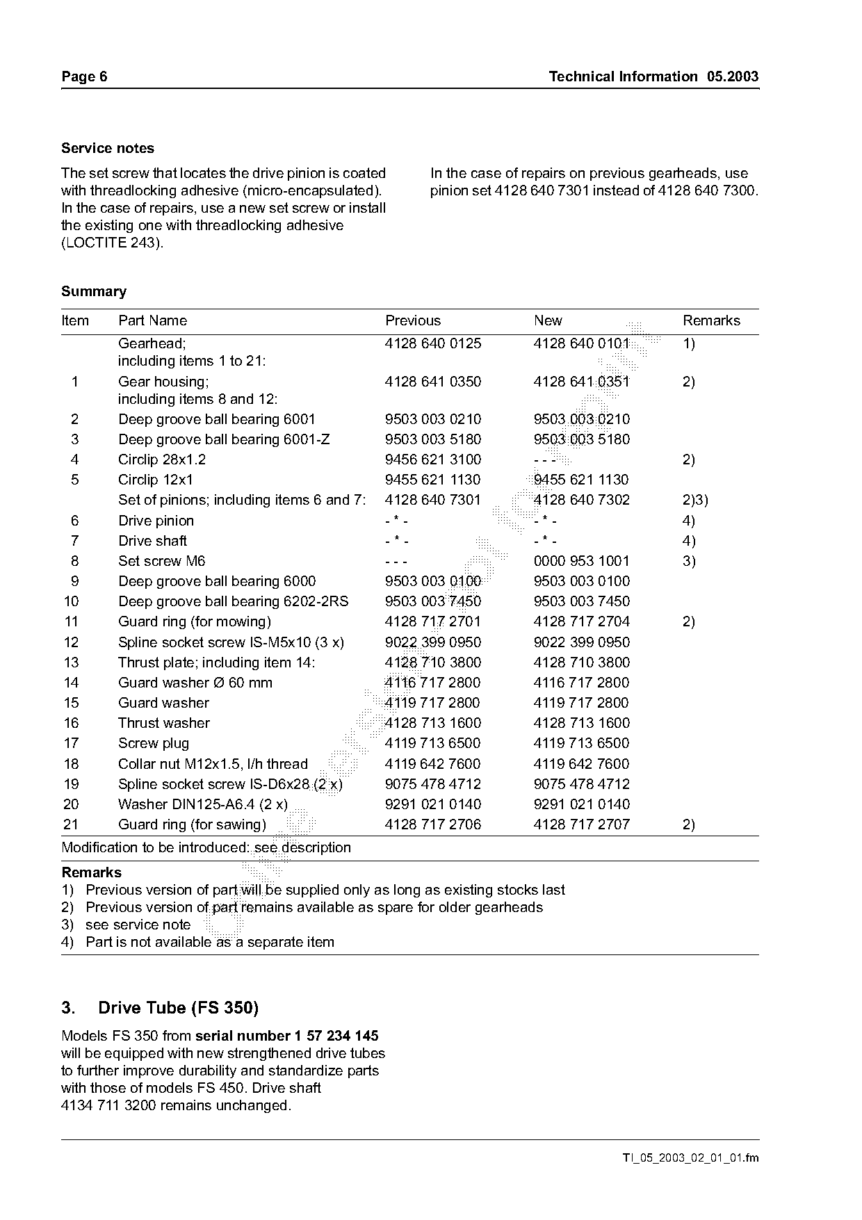
Summary

Item     Part Name                                   Previous              New                   Remarks

         Gearhead;                                   4128 640 0125         4128 640 0101         1)

         including items 1 to 21:
 1       Gear housing;                               4128 641 0350         4128 641 0351         2)
         including items 8 and 12:

 2       Deep groove ball bearing 6001               9503 003 0210         9503 003 0210
 3       Deep groove ball bearing 6001-Z             9503 003 5180         9503 003 5180
 4       Circlip 28x1.2                              9456 621 3100         ---                   2)

 5       Circlip 12x1                                9455 621 1130         9455 621 1130
         Set of pinions; including items 6 and 7:    4128 640 7301         4128 640 7302         2)3)
 6       Drive pinion                                -*-
                                                                   fo      -*-                   4)
 7       Drive shaft                                 -*-                   -*-                   4)
 8       Set screw M6                                ---                   0000 953 1001         3)
 9       Deep groove ball bearing 6000               9503 003 0100         9503 003 0100

10       Deep groove ball bearing 6202-2RS           9503 003 7450         9503 003 7450
11       Guard ring (for mowing)                     4128 717 2701         4128 717 2704         2)
12       Spline socket screw IS-M5x10 (3 x)          9022 399 0950         9022 399 0950
13       Thrust plate; including item 14:            4128 710 3800         4128 710 3800

14       Guard washer Ø 60 mm                        4116 717 2800         4116 717 2800

15       Guard washer                                4119 717 2800         4119 717 2800
16       Thrust washer                               4128 713 1600         4128 713 1600
17       Screw plug                                  4119 713 6500         4119 713 6500

18       Collar nut M12x1.5, l/h thread              4119 642 7600         4119 642 7600
19       Spline socket screw IS-D6x28 (2 x)          9075 478 4712         9075 478 4712

20       Washer DIN125-A6.4 (2 x)                    9291 021 0140         9291 021 0140
21       Guard ring (for sawing)                     4128 717 2706         4128 717 2707         2)
Modification to be introduced: see description

Remarks
1) Previous version of part will be supplied only as long as existing stocks last

2) Previous version of part remains available as spare for older gearheads
3) see service note
4) Part is not available as a separate item

3.     Drive Tube (FS 350)
Models FS 350 from serial number 1 57 234 145
will be equipped with new strengthened drive tubes
to further improve durability and standardize parts
with those of models FS 450. Drive shaft
4134 711 3200 remains unchanged.

                                                                                        TI_05_2003_02_01_01.fm
Page 7 of 10
Text of page 7 — search, copy, screen readers
Technical Information 05.2003                                                                                         Page 7

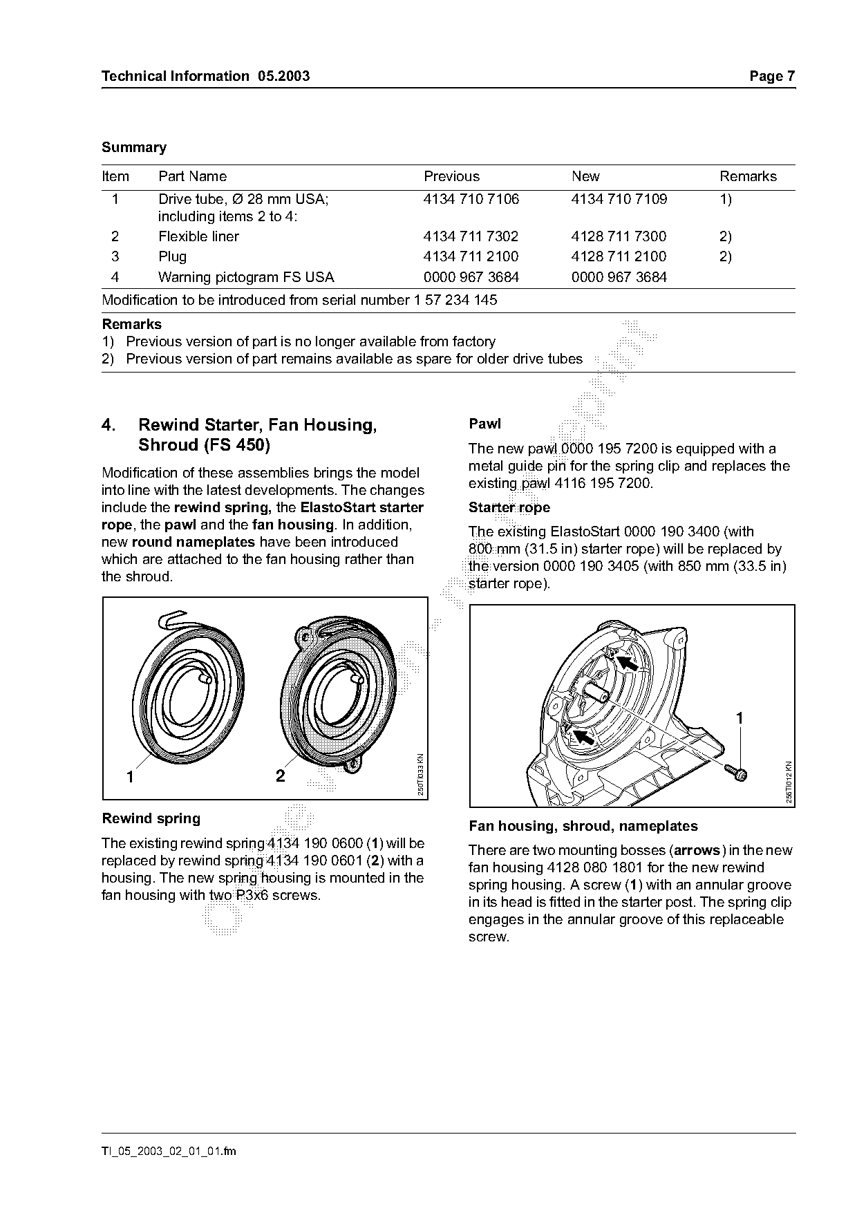
Summary

Item       Part Name                                       Previous                New                       Remarks
 1         Drive tube, Ø 28 mm USA;                        4134 710 7106           4134 710 7109             1)
           including items 2 to 4:
 2         Flexible liner                                  4134 711 7302           4128 711 7300             2)
 3         Plug                                            4134 711 2100           4128 711 2100             2)
 4         Warning pictogram FS USA                        0000 967 3684           0000 967 3684
Modification to be introduced from serial number 1 57 234 145
Remarks

1) Previous version of part is no longer available from factory

2) Previous version of part remains available as spare for older drive tubes

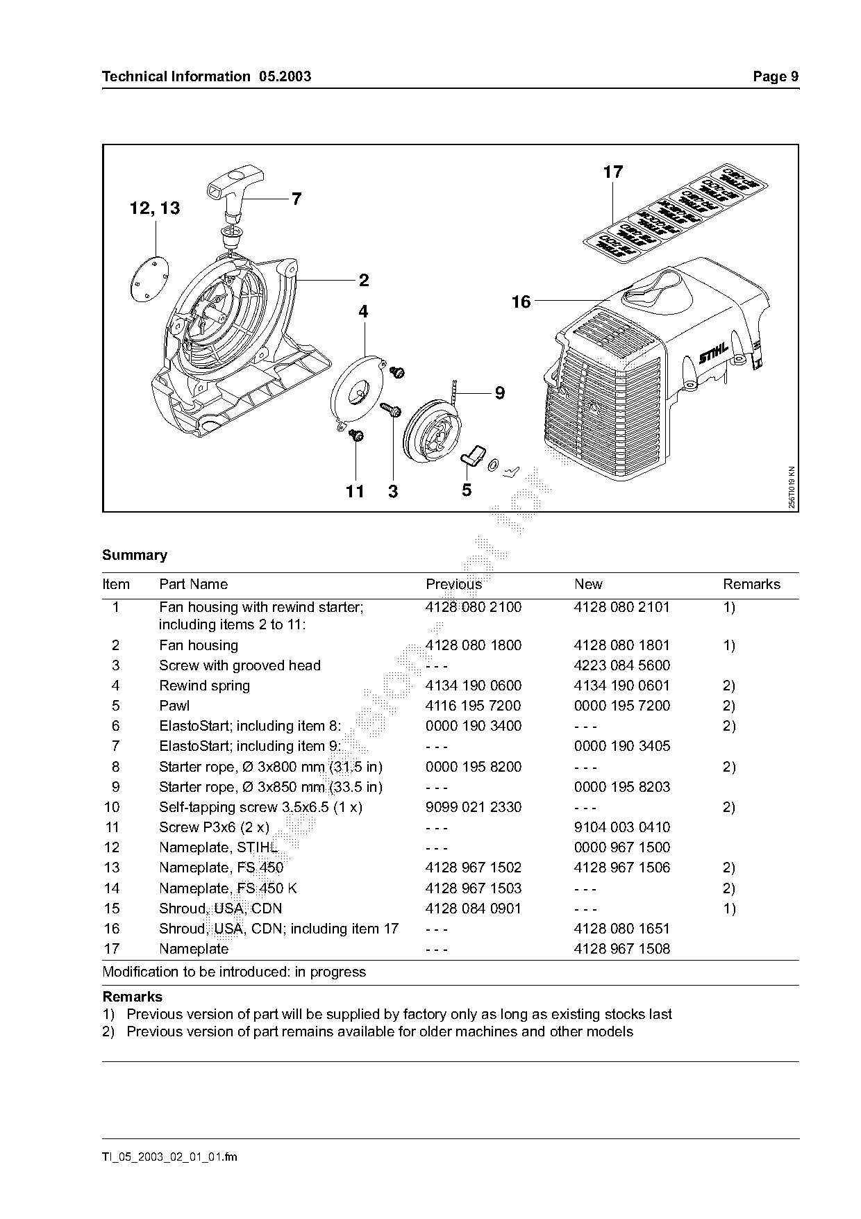
4.       Rewind Starter, Fan Housing,                            Pawl
         Shroud (FS 450)                                         The new pawl 0000 195 7200 is equipped with a

Modification of these assemblies brings the model                metal guide pin for the spring clip and replaces the
into line with the latest developments. The changes              existing pawl 4116 195 7200.
include the rewind spring, the ElastoStart starter
rope, the pawl and the fan housing. In addition,
                                                                 Starter rope
                                                                 The existing ElastoStart 0000 190 3400 (with
new round nameplates have been introduced
                                                                 800 mm (31.5 in) starter rope) will be replaced by
which are attached to the fan housing rather than
                                                                 the version 0000 190 3405 (with 850 mm (33.5 in)
the shroud.
                                                                 starter rope).

                                                                                                                  1
                                                  250TI033 KN

                                                                                                                          256TI012 KN
     1                      2

Rewind spring
                                                                 Fan housing, shroud, nameplates
The existing rewind spring 4134 190 0600 (1) will be

                                                                 There are two mounting bosses (arrows) in the new
replaced by rewind spring 4134 190 0601 (2) with a               fan housing 4128 080 1801 for the new rewind
housing. The new spring housing is mounted in the                spring housing. A screw (1) with an annular groove

fan housing with two P3x6 screws.                                in its head is fitted in the starter post. The spring clip
                                                                 engages in the annular groove of this replaceable
                                                                 screw.

TI_05_2003_02_01_01.fm
Page 8 of 10
Text of page 8 — search, copy, screen readers
Page 8                                                                             Technical Information 05.2003

                                                                The spring housing mounting screws in the fan
                        1                                       housing must be tightened down to a torque of
                                                                0.7 Nm (6 in lbs).
                                                                When tensioning the new rewind spring make sure
                                                                that the remaining reserve pull on the rope rotor is
                                                                1.5 revolutions.
                                                                The new starter rope (850 mm long(33.5 in)) must
                                                                not be installed in the previous version of the rewind
                                          2                     starter because the rewind spring will otherwise be

                                                  256TI013 KN
                                                                permanently damaged.

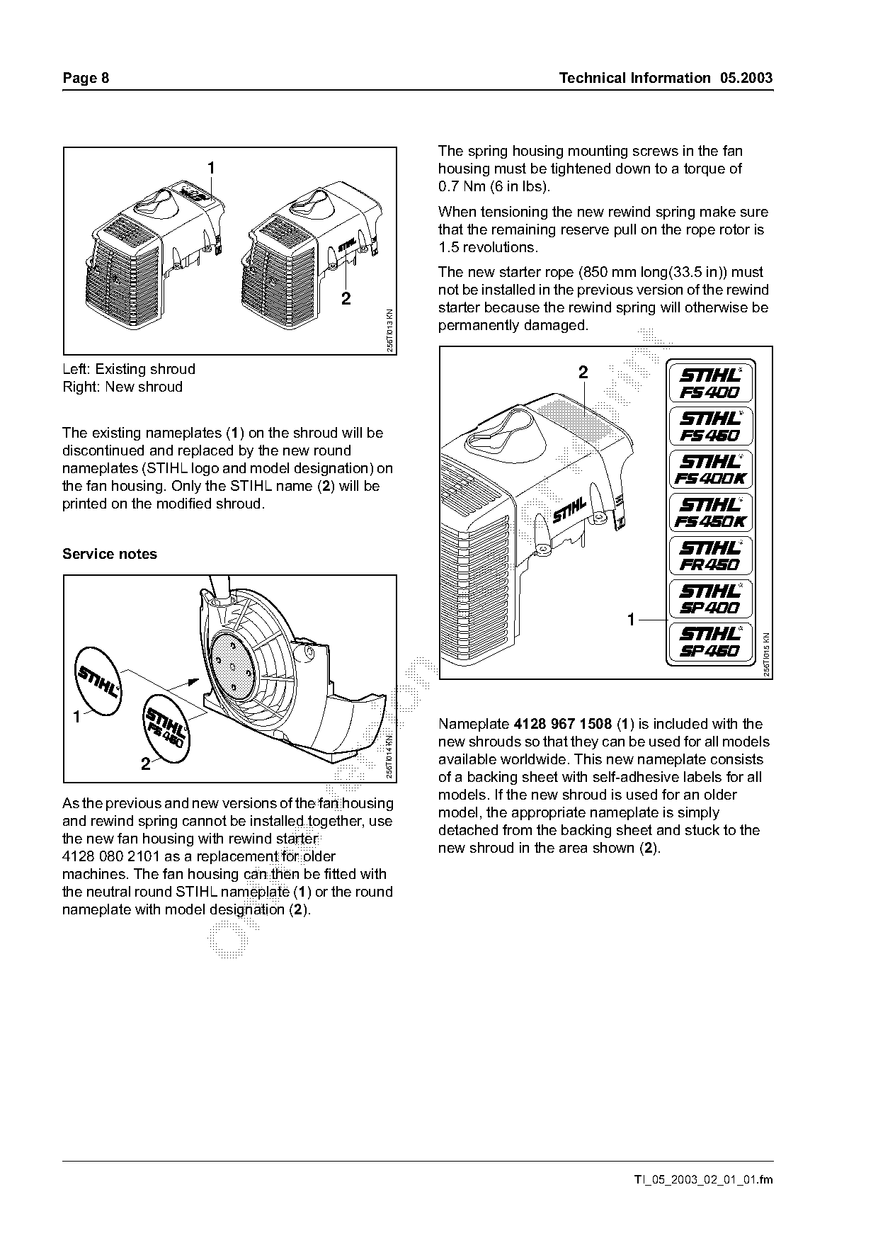
Left: Existing shroud                                                                 2
Right: New shroud

The existing nameplates (1) on the shroud will be
discontinued and replaced by the new round
nameplates (STIHL logo and model designation) on

the fan housing. Only the STIHL name (2) will be
printed on the modified shroud.
Service notes


                                                                                                                    256TI015 KN

 1                                                              Nameplate 4128 967 1508 (1) is included with the
                                                                new shrouds so that they can be used for all models
                                                 256TI014 KN

                                                                available worldwide. This new nameplate consists

            2
                                                                of a backing sheet with self-adhesive labels for all
                                                                models. If the new shroud is used for an older
As the previous and new versions of the fan housing

                                                                model, the appropriate nameplate is simply
and rewind spring cannot be installed together, use
                                                                detached from the backing sheet and stuck to the
the new fan housing with rewind starter
                                                                new shroud in the area shown (2).
4128 080 2101 as a replacement for older

machines. The fan housing can then be fitted with
the neutral round STIHL nameplate (1) or the round
nameplate with model designation (2).

                                                                                               TI_05_2003_02_01_01.fm
Page 9 of 10
Text of page 9 — search, copy, screen readers
Technical Information 05.2003                                                                       Page 9

                                                                                17
                              7
     12, 13

                                         2
                                                                   16
                                         4


                                                                                                         256TI019 KN
                                       11     3           5
Summary

Item     Part Name                                  Previous                New                Remarks

 1       Fan housing with rewind starter;           4128 080 2100           4128 080 2101      1)
         including items 2 to 11:
 2       Fan housing                                4128 080 1800           4128 080 1801      1)

 3       Screw with grooved head                    ---                     4223 084 5600
 4       Rewind spring                              4134 190 0600           4134 190 0601      2)

 5       Pawl                                       4116 195 7200           0000 195 7200      2)
 6       ElastoStart; including item 8:             0000 190 3400           ---                2)
 7       ElastoStart; including item 9:             ---                     0000 190 3405

 8       Starter rope, Ø 3x800 mm (31.5 in)         0000 195 8200           ---                2)
 9       Starter rope, Ø 3x850 mm (33.5 in)         ---                     0000 195 8203

10       Self-tapping screw 3.5x6.5 (1 x)           9099 021 2330           ---                2)
11       Screw P3x6 (2 x)                           ---                     9104 003 0410
12       Nameplate, STIHL                           ---                     0000 967 1500

13       Nameplate, FS 450                          4128 967 1502           4128 967 1506      2)
14       Nameplate, FS 450 K                        4128 967 1503           ---                2)

15       Shroud, USA, CDN                           4128 084 0901           ---                1)
16       Shroud, USA, CDN; including item 17        ---                     4128 080 1651
17       Nameplate                                  ---                     4128 967 1508
Modification to be introduced: in progress
Remarks
1) Previous version of part will be supplied by factory only as long as existing stocks last
2) Previous version of part remains available for older machines and other models

TI_05_2003_02_01_01.fm
Page 10 of 10
Text of page 10 — search, copy, screen readers
Page 10                                                                             Technical Information 05.2003

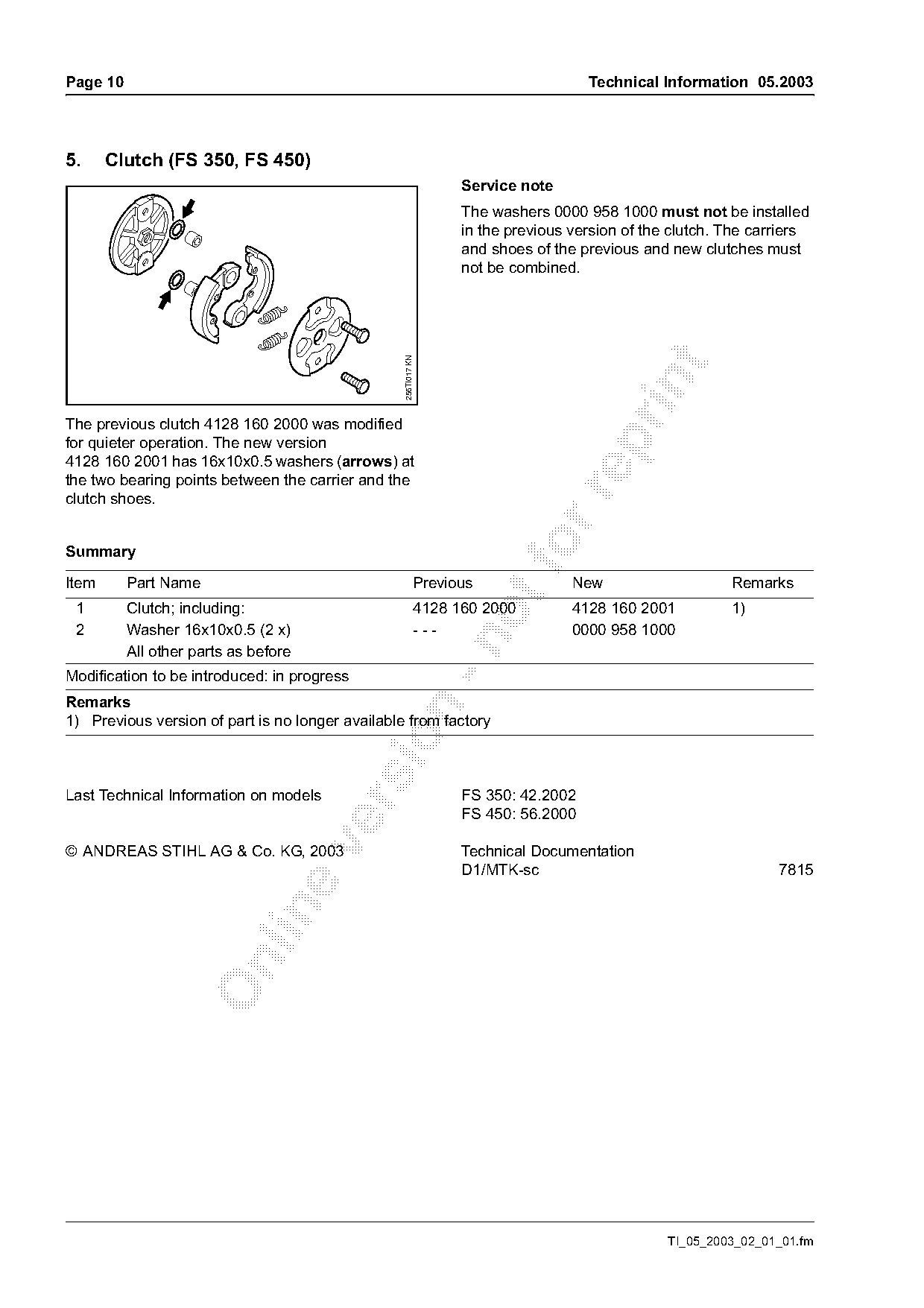
5.     Clutch (FS 350, FS 450)
                                                                  Service note
                                                                  The washers 0000 958 1000 must not be installed
                                                                  in the previous version of the clutch. The carriers
                                                                  and shoes of the previous and new clutches must
                                                                  not be combined.

                                                  256TI017 KN

The previous clutch 4128 160 2000 was modified

for quieter operation. The new version
4128 160 2001 has 16x10x0.5 washers (arrows) at
the two bearing points between the carrier and the

clutch shoes.

Summary                                                                  fo
Item      Part Name                                        Previous               New                    Remarks
 1        Clutch; including:                                4128 160 2000         4128 160 2001          1)
 2        Washer 16x10x0.5 (2 x)                            ---                   0000 958 1000

          All other parts as before
Modification to be introduced: in progress
Remarks

1) Previous version of part is no longer available from factory

Last Technical Information on models                              FS 350: 42.2002

                                                                  FS 450: 56.2000

© ANDREAS STIHL AG & Co. KG, 2003                                 Technical Documentation
                                                                  D1/MTK-sc                                     7815

                                                                                                TI_05_2003_02_01_01.fm
Most of these PDFs embed fonts with a shifted character map, so the text above was recovered rather than copied — read it as a faithful but imperfect transcription, and treat the page image above each block as the authority where the two disagree — the figures exist only there, because they are vector drawings that text extraction cannot keep.