Technical Information · issue 9 of 2003
Control Handle and Throttle Cable; New Carburetor C1Q-S82 / C1Q-S83, Shrouds, Grommet; Carburetor C1Q-S51; Rotating handlebar support / handlebar for mowing applications (FS 120, 200, 250 only); Clutch; Oil Seals (crankshaft); Crankshaft (FS 120,
IssueTI 9/2003
Part changes (3)
| Was | Becomes | What the bulletin says |
|---|---|---|
| 1123 121 3300 | 4134 121 3300 | 250TI032 KN 1123 121 3300 has been replaced by version 1 2 4134 121 3300. |
| 4137 790 1701 | 4128 790 1701 | 2 Swivelling the handlebar At the same time, the existing "universal" handlebar 4137 790 1701 will be replaced by the version for mowing applications, number 4128 790 1701. |
| 9640 003 1200 | 9640 003 1195 | Oil Seals (crankshaft) To facilitate installation, the 7 mm wide oil seals 9640 003 1200 (arrow) have been replaced by the new, 5 mm wide versions 9640 003 1195. |
Full text
Page 1 of 23
Text of page 1 — search, copy, screen readers
STIH)

Technical Information                                                               09.2003

  STIHL BT 120 C Earth Auger                             – Series 4313
  STIHL FS 120, 200, 250 Brushcutters                    – Series 4134
  STIHL FS 350 Clearing Saws                             – Series 4134

  Contents
  1. Control Handle and Throttle Cable
  2. New Carburetor C1Q-S82 /
     C1Q-S83, Shrouds, Grommet
  3. Carburetor C1Q-S51
  4. Rotating handlebar support / handlebar for mowing applications (FS 250 only)
  5. Clutch
  6. Oil Seals (crankshaft)
  7. Crankshaft
     (FS 120, 200, 250, BT 120 only)
  8. Rewind Starter / Spring Housing Fastening

  1.     Control Handle and Throttle Cable
  New control handles with throttle cable will be        –   Control handle
  installed to further improve operation. The new
                                                         –   Throttle cable
  assemblies will be introduced on all bike-handled
  and loop-handled machines.                             –   Throttle cable retainer
  At the same time, a new carburetor has also been       –   Short-circuit wire between retainer and
  introduced. See chapter 2.1, "Carburetor with three        ignition module
  adjusting screws".                                     –   Carburetor housing
  The complete set of modifications comprises the        –   Contact plate / gasket
  following parts or assemblies:
                                                         –   Pin for attaching the throttle cable to the
                                                             carburetor
                                                         The features and assembly of the new parts are
                                                         described in chapters 1.1 to 1.9.

  TI_09_2003_02_01_02.fm                                                               englisch / English USA
Page 2 of 23
Text of page 2 — search, copy, screen readers
Page 2                                                                                  Technical Information 09.2003

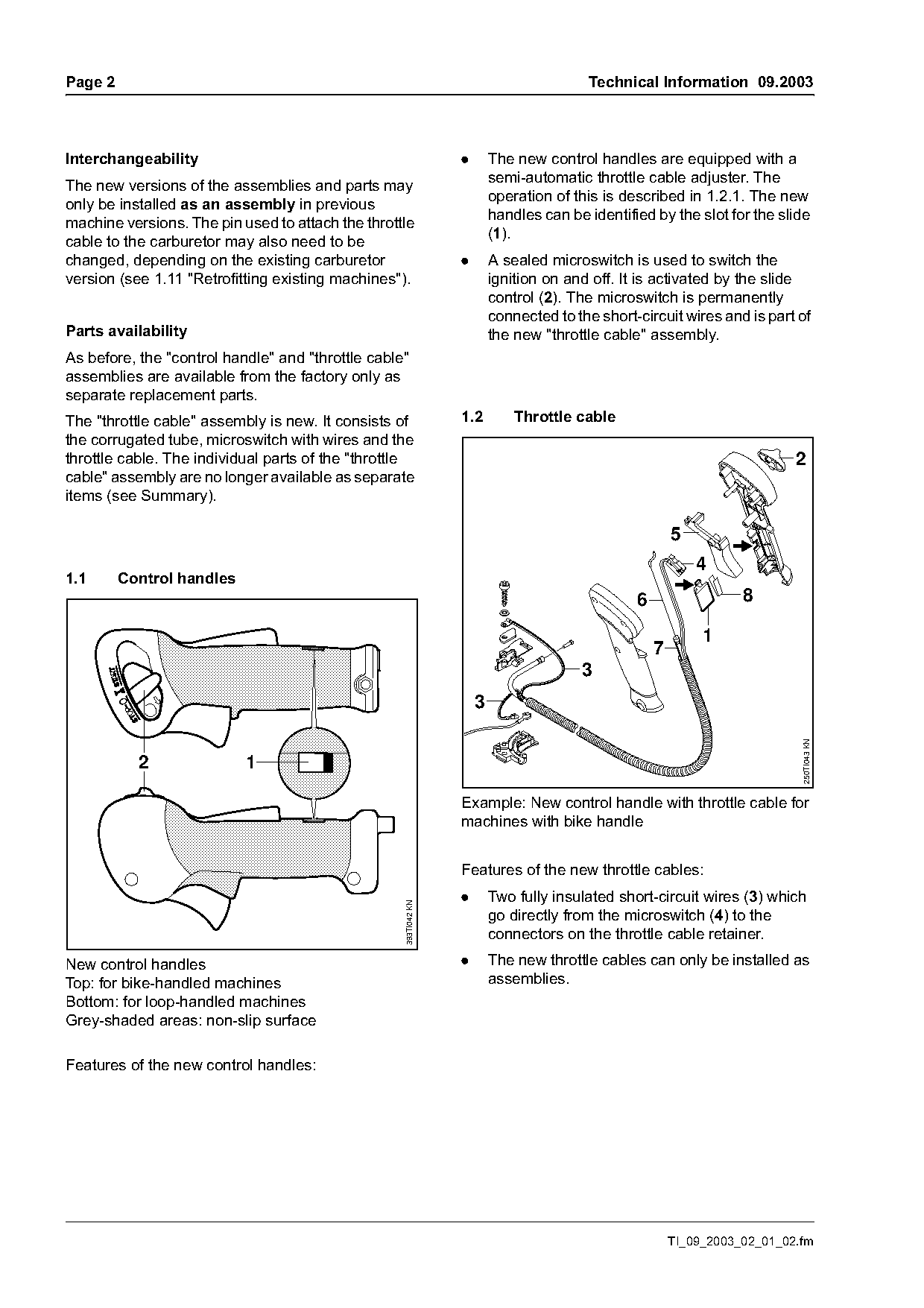
Interchangeability                                               .       The new control handles are equipped with a
                                                                         semi-automatic throttle cable adjuster. The
The new versions of the assemblies and parts may
                                                                         operation of this is described in 1.2.1. The new
only be installed as an assembly in previous
                                                                         handles can be identified by the slot for the slide
machine versions. The pin used to attach the throttle
                                                                         (1).
cable to the carburetor may also need to be
changed, depending on the existing carburetor                    .       A sealed microswitch is used to switch the
version (see 1.11 "Retrofitting existing machines").                     ignition on and off. It is activated by the slide
                                                                         control (2). The microswitch is permanently
                                                                         connected to the short-circuit wires and is part of
Parts availability                                                       the new "throttle cable" assembly.
As before, the "control handle" and "throttle cable"
assemblies are available from the factory only as
separate replacement parts.
The "throttle cable" assembly is new. It consists of             1.2         Throttle cable
the corrugated tube, microswitch with wires and the
throttle cable. The individual parts of the "throttle                                                                      2
cable" assembly are no longer available as separate
items (see Summary).

                                                                                                        5
                                                                                                            4
1.1      Control handles
                                                                                                6                  8

                                                                                                             1
                                                                                                    7
                                                                                       3
                                                                     3

                                                                                                                            250TI043 KN
           2               1

                                                                 Example: New control handle with throttle cable for
                                                                 machines with bike handle

                                                                 Features of the new throttle cables:
                                                                 .       Two fully insulated short-circuit wires (3) which
                                                   393TI042 KN

                                                                         go directly from the microswitch (4) to the
                                                                         connectors on the throttle cable retainer.
New control handles                                              .       The new throttle cables can only be installed as
Top: for bike-handled machines                                           assemblies.
Bottom: for loop-handled machines
Grey-shaded areas: non-slip surface

Features of the new control handles:

                                                                                                        TI_09_2003_02_01_02.fm
Page 3 of 23
Text of page 3 — search, copy, screen readers
Technical Information 09.2003                                                                                    Page 3

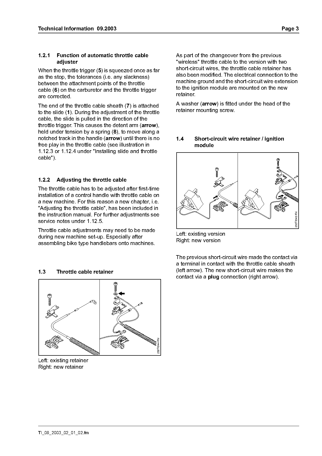
1.2.1   Function of automatic throttle cable                        As part of the changeover from the previous
        adjuster                                                    "wireless" throttle cable to the version with two
When the throttle trigger (5) is squeezed once as far               short-circuit wires, the throttle cable retainer has
as the stop, the tolerances (i.e. any slackness)                    also been modified. The electrical connection to the
between the attachment points of the throttle                       machine ground and the short-circuit wire extension
cable (6) on the carburetor and the throttle trigger                to the ignition module are mounted on the new
are corrected.                                                      retainer.

The end of the throttle cable sheath (7) is attached                A washer (arrow) is fitted under the head of the
to the slide (1). During the adjustment of the throttle             retainer mounting screw.
cable, the slide is pulled in the direction of the
throttle trigger. This causes the detent arm (arrow),
held under tension by a spring (8), to move along a
notched track in the handle (arrow) until there is no               1.4     Short-circuit wire retainer / ignition
free play in the throttle cable (see illustration in                        module
1.12.3 or 1.12.4 under "Installing slide and throttle
cable").

1.2.2   Adjusting the throttle cable
The throttle cable has to be adjusted after first-time
installation of a control handle with throttle cable on
a new machine. For this reason a new chapter, i.e.
"Adjusting the throttle cable", has been included in
the instruction manual. For further adjustments see

                                                                                                                       250TI045 KN
service notes under 1.12.5.
Throttle cable adjustments may need to be made
                                                                    Left: existing version
during new machine set-up. Especially after
                                                                    Right: new version
assembling bike type handlebars onto machines.

                                                                    The previous short-circuit wire made the contact via
                                                                    a terminal in contact with the throttle cable sheath
1.3     Throttle cable retainer                                     (left arrow). The new short-circuit wire makes the
                                                                    contact via a plug connection (right arrow).
                                                      250TI044 KN

Left: existing retainer
Right: new retainer

TI_09_2003_02_01_02.fm
Page 4 of 23
Text of page 4 — search, copy, screen readers
Page 4                                                                                   Technical Information 09.2003

1.5      Carburetor housing                                          1.7     Throttle cable attachment to carburetor

                                                      250TI046 KN

                                                                                                                            250TI048 KN
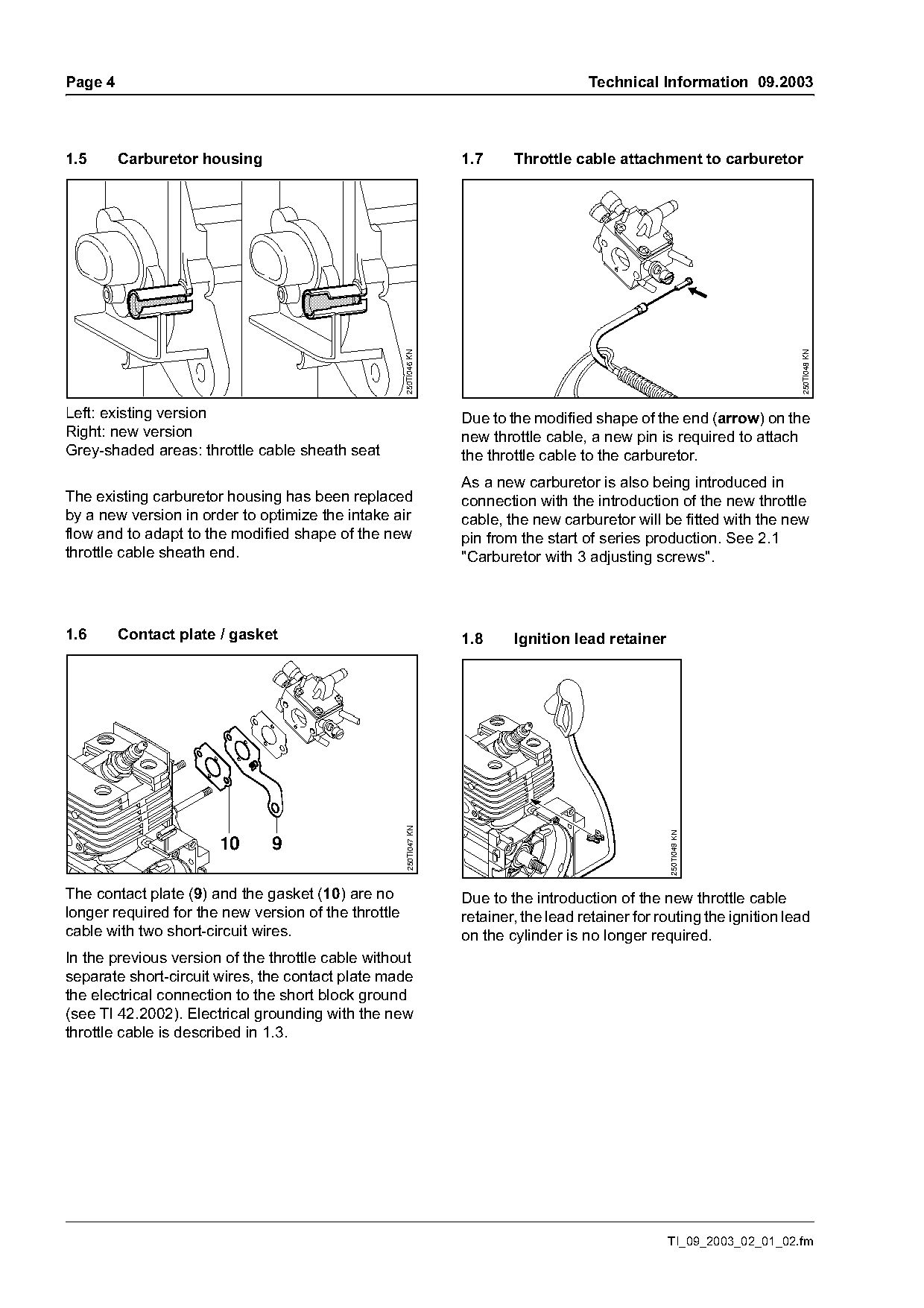
Left: existing version                                               Due to the modified shape of the end (arrow) on the
Right: new version                                                   new throttle cable, a new pin is required to attach
Grey-shaded areas: throttle cable sheath seat                        the throttle cable to the carburetor.
                                                                     As a new carburetor is also being introduced in
The existing carburetor housing has been replaced                    connection with the introduction of the new throttle
by a new version in order to optimize the intake air                 cable, the new carburetor will be fitted with the new
flow and to adapt to the modified shape of the new                   pin from the start of series production. See 2.1
throttle cable sheath end.                                           "Carburetor with 3 adjusting screws".

1.6      Contact plate / gasket                                      1.8     Ignition lead retainer
                                                       250TI047 KN

                                                                                                       250TI049 KN

                       10      9

The contact plate (9) and the gasket (10) are no                     Due to the introduction of the new throttle cable
longer required for the new version of the throttle                  retainer, the lead retainer for routing the ignition lead
cable with two short-circuit wires.                                  on the cylinder is no longer required.
In the previous version of the throttle cable without
separate short-circuit wires, the contact plate made
the electrical connection to the short block ground
(see TI 42.2002). Electrical grounding with the new
throttle cable is described in 1.3.

                                                                                                      TI_09_2003_02_01_02.fm
Page 5 of 23
Text of page 5 — search, copy, screen readers
Technical Information 09.2003                                                                             Page 5

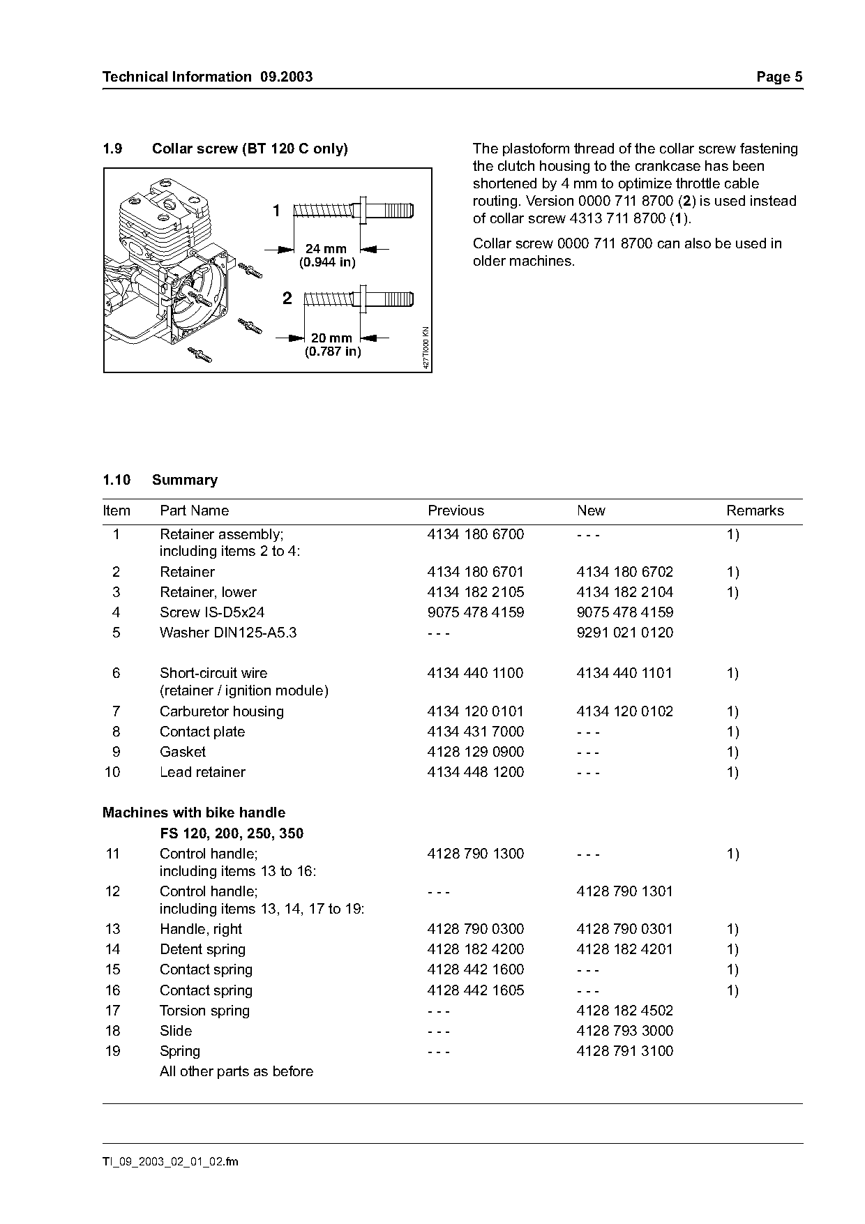
1.9     Collar screw (BT 120 C only)                          The plastoform thread of the collar screw fastening
                                                              the clutch housing to the crankcase has been
                                                              shortened by 4 mm to optimize throttle cable
                                                              routing. Version 0000 711 8700 (2) is used instead
                           1                                  of collar screw 4313 711 8700 (1).

                                    24 mm                     Collar screw 0000 711 8700 can also be used in
                                   (0.944 in)                 older machines.


                                                427TI000 KN
                                    20 mm
                                   (0.787 in)

1.10    Summary

Item     Part Name                                     Previous               New                    Remarks
 1       Retainer assembly;                            4134 180 6700          ---                    1)
         including items 2 to 4:
 2       Retainer                                      4134 180 6701          4134 180 6702          1)
 3       Retainer, lower                               4134 182 2105          4134 182 2104          1)
 4       Screw IS-D5x24                                9075 478 4159          9075 478 4159
 5       Washer DIN125-A5.3                            ---                    9291 021 0120

 6       Short-circuit wire                            4134 440 1100          4134 440 1101          1)
         (retainer / ignition module)
 7       Carburetor housing                            4134 120 0101          4134 120 0102          1)
 8       Contact plate                                 4134 431 7000          ---                    1)
 9       Gasket                                        4128 129 0900          ---                    1)
10       Lead retainer                                 4134 448 1200          ---                    1)

Machines with bike handle
       FS 120, 200, 250, 350
11     Control handle;                                 4128 790 1300          ---                    1)
       including items 13 to 16:
12     Control handle;                                 ---                    4128 790 1301
       including items 13, 14, 17 to 19:
13     Handle, right                                   4128 790 0300          4128 790 0301          1)
14     Detent spring                                   4128 182 4200          4128 182 4201          1)
15     Contact spring                                  4128 442 1600          ---                    1)
16     Contact spring                                  4128 442 1605          ---                    1)
17     Torsion spring                                  ---                    4128 182 4502
18     Slide                                           ---                    4128 793 3000
19     Spring                                          ---                    4128 791 3100
       All other parts as before

TI_09_2003_02_01_02.fm
Page 6 of 23
Text of page 6 — search, copy, screen readers
Page 6                                                               Technical Information 09.2003

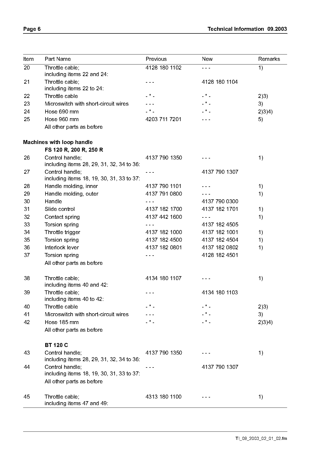
Item     Part Name                                 Previous        New                  Remarks
20       Throttle cable;                           4128 180 1102   ---                  1)
         including items 22 and 24:
21       Throttle cable;                           ---             4128 180 1104
         including items 22 to 24:
22       Throttle cable                            -*-             -*-                  2)3)
23       Microswitch with short-circuit wires      ---             -*-                  3)
24       Hose 690 mm                               -*-             -*-                  2)3)4)
25       Hose 960 mm                               4203 711 7201   ---                  5)
         All other parts as before

Machines with loop handle
       FS 120 R, 200 R, 250 R
26     Control handle;                             4137 790 1350   ---                  1)
       including items 28, 29, 31, 32, 34 to 36:
27     Control handle;                             ---             4137 790 1307
       including items 18, 19, 30, 31, 33 to 37:
28     Handle molding, inner                       4137 790 1101   ---                  1)
29     Handle molding, outer                       4137 791 0800   ---                  1)
30     Handle                                      ---             4137 790 0300
31     Slide control                               4137 182 1700   4137 182 1701        1)
32     Contact spring                              4137 442 1600   ---                  1)
33     Torsion spring                              ---             4137 182 4505
34     Throttle trigger                            4137 182 1000   4137 182 1001        1)
35     Torsion spring                              4137 182 4500   4137 182 4504        1)
36     Interlock lever                             4137 182 0801   4137 182 0802        1)
37     Torsion spring                              ---             4128 182 4501
       All other parts as before

38       Throttle cable;                           4134 180 1107   ---                  1)
         including items 40 and 42:
39       Throttle cable;                           ---             4134 180 1103
         including items 40 to 42:
40       Throttle cable                            -*-             -*-                  2)3)
41       Microswitch with short-circuit wires      ---             -*-                  3)
42       Hose 185 mm                               -*-             -*-                  2)3)4)
         All other parts as before

         BT 120 C
43       Control handle;                           4137 790 1350   ---                  1)
         including items 28, 29, 31, 32, 34 to 36:
44       Control handle;                           ---             4137 790 1307
         including items 18, 19, 30, 31, 33 to 37:
         All other parts as before

45       Throttle cable;                           4313 180 1100   ---                  1)
         including items 47 and 49:

                                                                               TI_09_2003_02_01_02.fm
Page 7 of 23
Text of page 7 — search, copy, screen readers
Technical Information 09.2003                                                                               Page 7

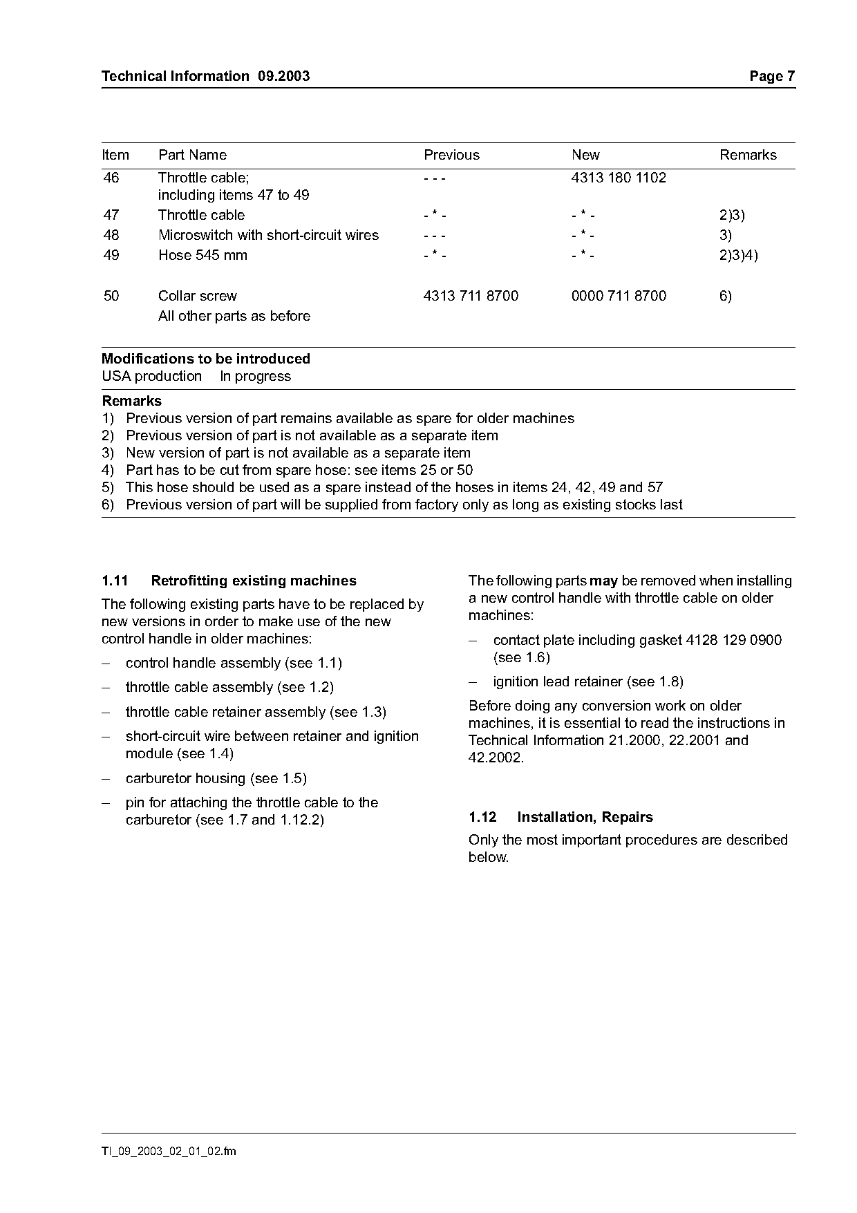
Item      Part Name                                     Previous                New                    Remarks
46        Throttle cable;                               ---                     4313 180 1102
          including items 47 to 49
47        Throttle cable                                -*-                     -*-                    2)3)
48        Microswitch with short-circuit wires          ---                     -*-                    3)
49        Hose 545 mm                                   -*-                     -*-                    2)3)4)

50        Collar screw                                  4313 711 8700           0000 711 8700          6)
          All other parts as before

Modifications to be introduced
USA production In progress
Remarks
1) Previous version of part remains available as spare for older machines
2) Previous version of part is not available as a separate item
3) New version of part is not available as a separate item
4) Part has to be cut from spare hose: see items 25 or 50
5) This hose should be used as a spare instead of the hoses in items 24, 42, 49 and 57
6) Previous version of part will be supplied from factory only as long as existing stocks last

1.11     Retrofitting existing machines                       The following parts may be removed when installing
The following existing parts have to be replaced by           a new control handle with throttle cable on older
new versions in order to make use of the new                  machines:
control handle in older machines:                             –    contact plate including gasket 4128 129 0900
–    control handle assembly (see 1.1)                             (see 1.6)

–    throttle cable assembly (see 1.2)                        –    ignition lead retainer (see 1.8)

–    throttle cable retainer assembly (see 1.3)               Before doing any conversion work on older
                                                              machines, it is essential to read the instructions in
–    short-circuit wire between retainer and ignition         Technical Information 21.2000, 22.2001 and
     module (see 1.4)                                         42.2002.
–    carburetor housing (see 1.5)
–    pin for attaching the throttle cable to the
     carburetor (see 1.7 and 1.12.2)                          1.12     Installation, Repairs
                                                              Only the most important procedures are described
                                                              below.

TI_09_2003_02_01_02.fm
Page 8 of 23
Text of page 8 — search, copy, screen readers
Page 8                                                                                Technical Information 09.2003

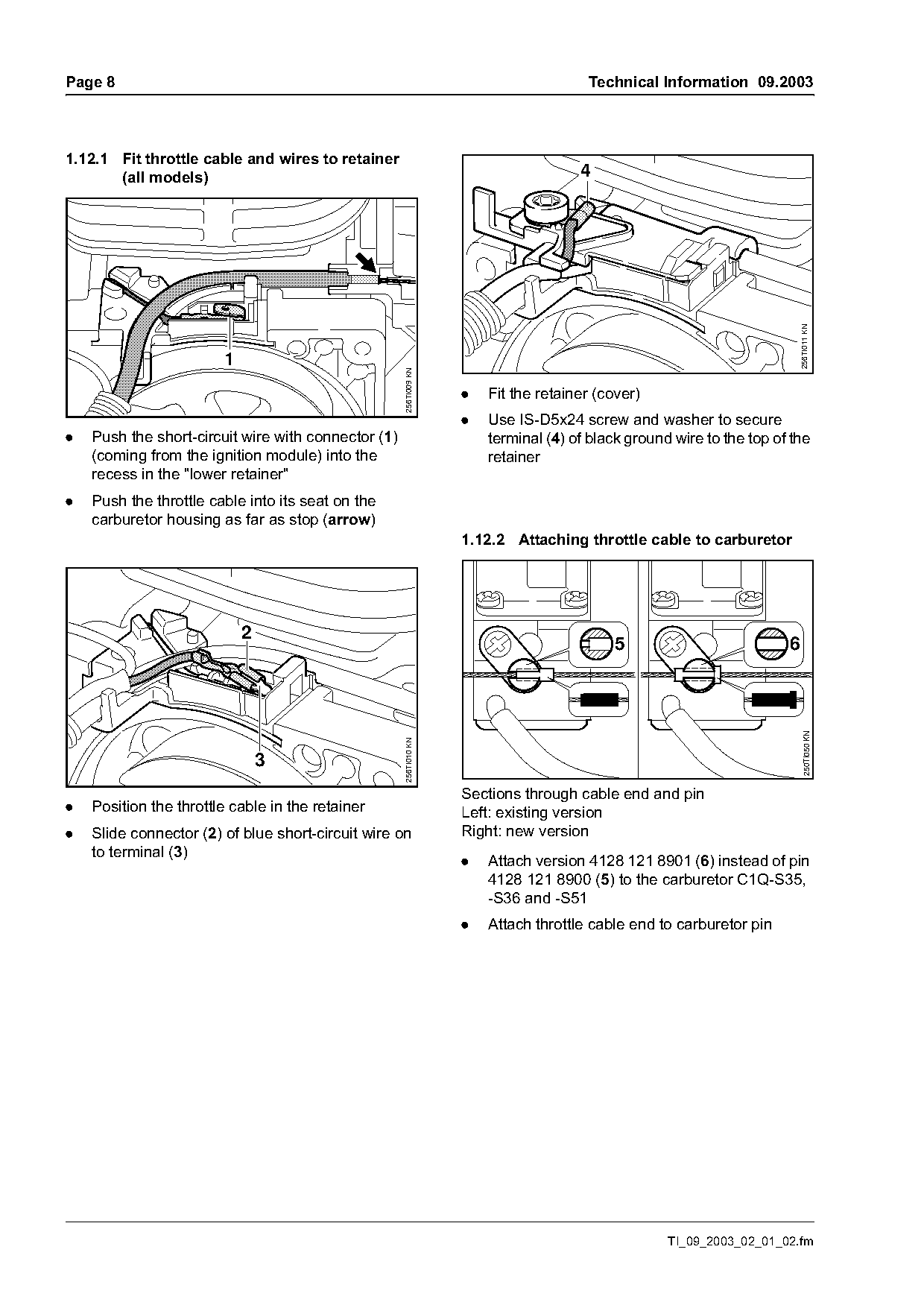
1.12.1 Fit throttle cable and wires to retainer
       (all models)                                                                  4

                                                                                                                          256TI011 KN
                        1

                                                     256TI009 KN
                                                                   .   Fit the retainer (cover)
                                                                   .   Use IS-D5x24 screw and washer to secure
.   Push the short-circuit wire with connector (1)                     terminal (4) of black ground wire to the top of the
    (coming from the ignition module) into the                         retainer
    recess in the "lower retainer"
.   Push the throttle cable into its seat on the
    carburetor housing as far as stop (arrow)
                                                                   1.12.2 Attaching throttle cable to carburetor

                            2
                                                                                           5                          6

                                                                                                                            250TI050 KN
                                                     256TI010 KN

                                3
                                                                   Sections through cable end and pin
.   Position the throttle cable in the retainer                    Left: existing version
.   Slide connector (2) of blue short-circuit wire on              Right: new version
    to terminal (3)
                                                                   .   Attach version 4128 121 8901 (6) instead of pin
                                                                       4128 121 8900 (5) to the carburetor C1Q-S35,
                                                                       -S36 and -S51
                                                                   .   Attach throttle cable end to carburetor pin

                                                                                                   TI_09_2003_02_01_02.fm
Page 9 of 23
Text of page 9 — search, copy, screen readers
Technical Information 09.2003                                                                                          Page 9

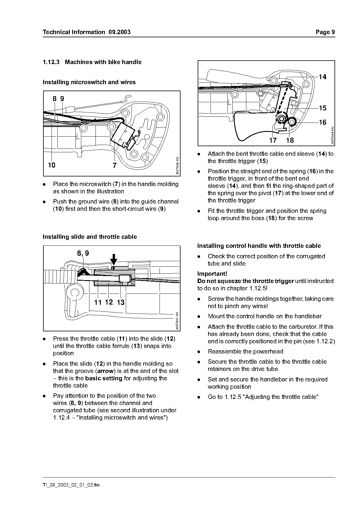
1.12.3 Machines with bike handle

                                                                                                                         14
Installing microswitch and wires

     8 9
                                                                                                                         15


                                                                                                                              393TI048 KN
                                                                                                    17    18
                                                                       .   Attach the bent throttle cable end sleeve (14) to

                                                         393TI046 KN
                                                                           the throttle trigger (15)
    10                      7
                                                                       .   Position the straight end of the spring (16) in the
                                                                           throttle trigger, in front of the bent end
.    Place the microswitch (7) in the handle molding                       sleeve (14), and then fit the ring-shaped part of
     as shown in the illustration                                          the spring over the pivot (17) at the lower end of
.    Push the ground wire (8) into the guide channel                       the throttle trigger
     (10) first and then the short-circuit wire (9)                    .   Fit the throttle trigger and position the spring
                                                                           loop around the boss (18) for the screw

Installing slide and throttle cable
                                                                       Installing control handle with throttle cable
              8, 9                                                     .   Check the correct position of the corrugated
                                                                           tube and slide
                                                                       Important!
                                                                       Do not squeeze the throttle trigger until instructed
                                                                       to do so in chapter 1.12.5!
                                                                       .   Screw the handle moldings together, taking care
                     11 12 13                                              not to pinch any wires!
                                                         393TI047 KN

                                                                       .   Mount the control handle on the handlebar
                                                                       .   Attach the throttle cable to the carburetor. If this
                                                                           has already been done, check that the cable
.    Press the throttle cable (11) into the slide (12)                     end is correctly positioned in the pin (see 1.12.2)
     until the throttle cable ferrule (13) snaps into
     position                                                          .   Reassemble the powerhead

.    Place the slide (12) in the handle molding so                     .   Secure the throttle cable to the throttle cable
     that the groove (arrow) is at the end of the slot                     retainers on the drive tube
     – this is the basic setting for adjusting the                     .   Set and secure the handlebar in the required
     throttle cable                                                        working position
.    Pay attention to the position of the two                          .   Go to 1.12.5 "Adjusting the throttle cable"
     wires (8, 9) between the channel and
     corrugated tube (see second illustration under
     1.12.4 – "Installing microswitch and wires")

TI_09_2003_02_01_02.fm
Page 10 of 23
Text of page 10 — search, copy, screen readers
Page 10                                                                                  Technical Information 09.2003

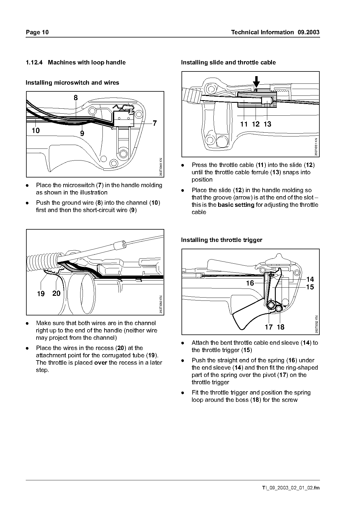
1.12.4 Machines with loop handle                                     Installing slide and throttle cable

Installing microswitch and wires


                                                  7                                         11 12 13
    10                 9

                                                                                                                             393TI051 KN
                                                       393TI049 KN
                                                                     .   Press the throttle cable (11) into the slide (12)
                                                                         until the throttle cable ferrule (13) snaps into
                                                                         position
.    Place the microswitch (7) in the handle molding
     as shown in the illustration                                    .   Place the slide (12) in the handle molding so
                                                                         that the groove (arrow) is at the end of the slot –
.    Push the ground wire (8) into the channel (10)                      this is the basic setting for adjusting the throttle
     first and then the short-circuit wire (9)                           cable

                                                                     Installing the throttle trigger

                                                                                                                       14
                                                                                               16
                                                                                                                       15
     19    20
                                                       393TI050 KN

                                                                                                                               393TI052 KN

.    Make sure that both wires are in the channel
     right up to the end of the handle (neither wire                                                   17 18
     may project from the channel)
                                                                     .   Attach the bent throttle cable end sleeve (14) to
.    Place the wires in the recess (20) at the                           the throttle trigger (15)
     attachment point for the corrugated tube (19).
     The throttle is placed over the recess in a later               .   Push the straight end of the spring (16) under
     step.                                                               the end sleeve (14) and then fit the ring-shaped
                                                                         part of the spring over the pivot (17) on the
                                                                         throttle trigger
                                                                     .   Fit the throttle trigger and position the spring
                                                                         loop around the boss (18) for the screw

                                                                                                      TI_09_2003_02_01_02.fm
Page 11 of 23
Text of page 11 — search, copy, screen readers
Technical Information 09.2003                                                                            Page 11

Installing control handle with throttle cable              –   on bike-handled machines, after a big change in
                                                               the position of the handlebar (e.g. change
.   Check the correct position of the corrugated
                                                               between transport and operating position).
    tube and slide
Important!                                                 –   after the throttle cable has stretched, or after a
Do not squeeze the throttle trigger until instructed           change in the position of the slide as a result of
to do so in chapter 1.12.5!                                    force due to the throttle cable snagging on an
                                                               object during operation.
.   Screw the handle moldings together, taking care
    not to pinch any wires!
.   Attach the throttle cable to the carburetor. If this
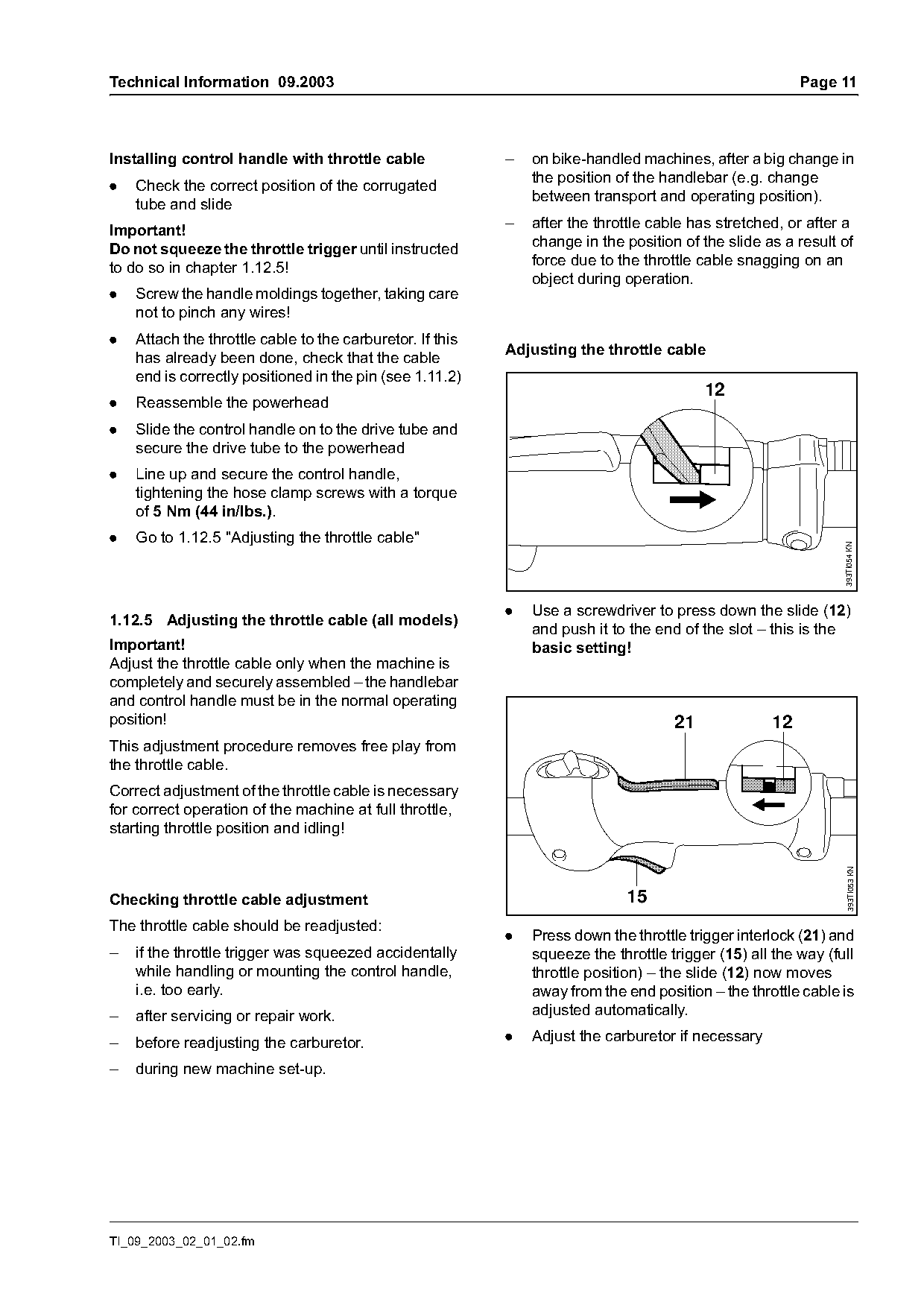
                                                           Adjusting the throttle cable
    has already been done, check that the cable
    end is correctly positioned in the pin (see 1.11.2)
                                                                                          12
.   Reassemble the powerhead
.   Slide the control handle on to the drive tube and
    secure the drive tube to the powerhead
.   Line up and secure the control handle,
    tightening the hose clamp screws with a torque
    of 5 Nm (44 in/lbs.).
.   Go to 1.12.5 "Adjusting the throttle cable"

                                                                                                                393TI054 KN
                                                           .   Use a screwdriver to press down the slide (12)
1.12.5 Adjusting the throttle cable (all models)
                                                               and push it to the end of the slot – this is the
Important!                                                     basic setting!
Adjust the throttle cable only when the machine is
completely and securely assembled – the handlebar
and control handle must be in the normal operating
position!                                                                            21             12
This adjustment procedure removes free play from
the throttle cable.
Correct adjustment of the throttle cable is necessary
for correct operation of the machine at full throttle,
starting throttle position and idling!
                                                                                                                 393TI053 KN

Checking throttle cable adjustment                                           15
The throttle cable should be readjusted:
                                                           .   Press down the throttle trigger interlock (21) and
–   if the throttle trigger was squeezed accidentally          squeeze the throttle trigger (15) all the way (full
    while handling or mounting the control handle,             throttle position) – the slide (12) now moves
    i.e. too early.                                            away from the end position – the throttle cable is
–   after servicing or repair work.                            adjusted automatically.

–   before readjusting the carburetor.                     .   Adjust the carburetor if necessary

–   during new machine set-up.

TI_09_2003_02_01_02.fm
Page 12 of 23
Text of page 12 — search, copy, screen readers
Page 12                                                                                 Technical Information 09.2003

2.       New Carburetor C1Q-S82 /                                   2.1.1   Mechanical design
         C1Q-S83, Shrouds, Grommet

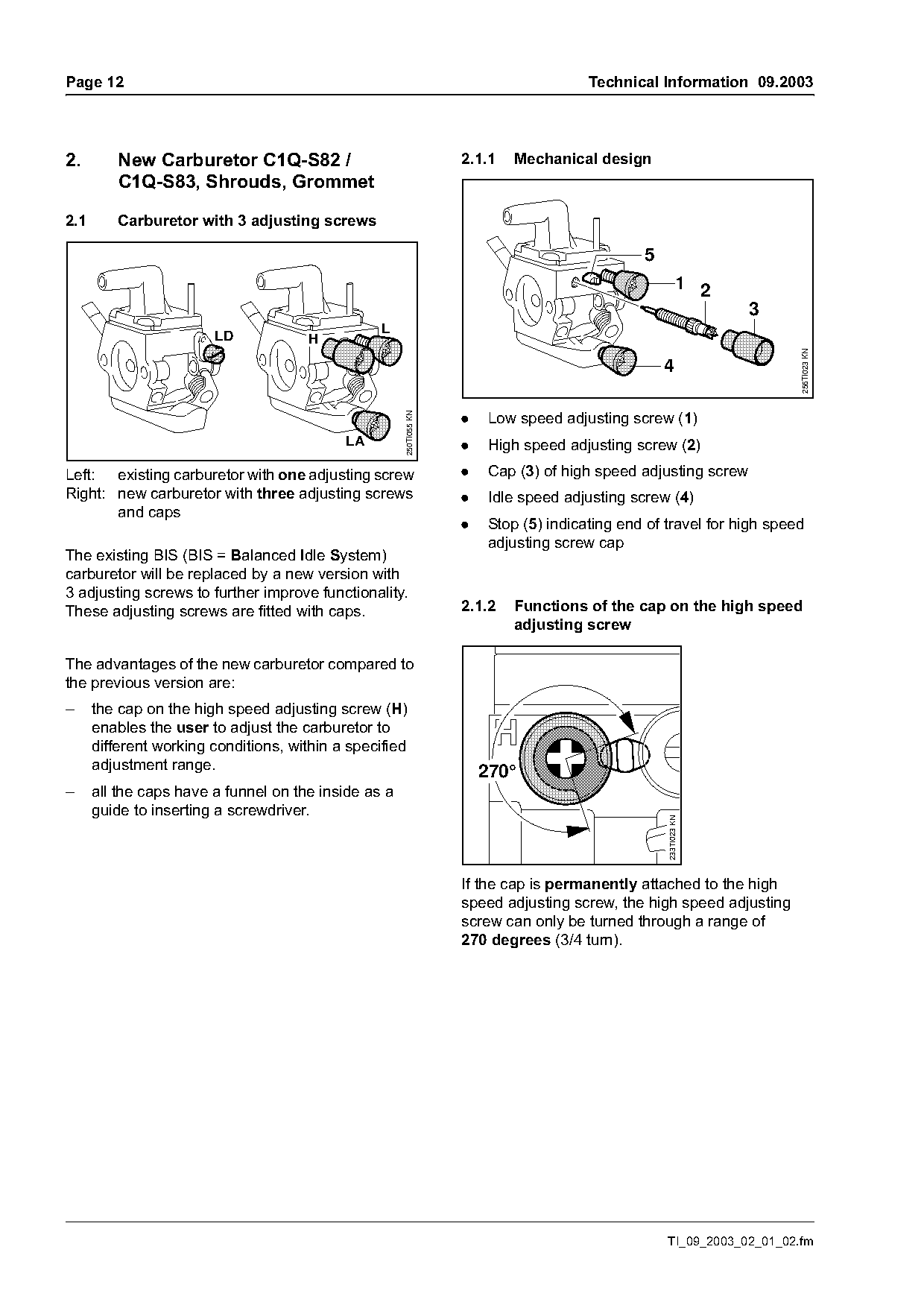
2.1      Carburetor with 3 adjusting screws

                                                                                                5
                                                                                                           1 2
                                                                                                                  3
                        LD            H

                                                                                                                        256TI023 KN
                                                                                                    4

                                                                    .    Low speed adjusting screw (1)
                                                      250TI055 KN

                                            LA                      .    High speed adjusting screw (2)
Left: existing carburetor with one adjusting screw                  .    Cap (3) of high speed adjusting screw
Right: new carburetor with three adjusting screws                   .    Idle speed adjusting screw (4)
       and caps
                                                                    .    Stop (5) indicating end of travel for high speed
                                                                         adjusting screw cap
The existing BIS (BIS = Balanced Idle System)
carburetor will be replaced by a new version with
3 adjusting screws to further improve functionality.
These adjusting screws are fitted with caps.                        2.1.2   Functions of the cap on the high speed
                                                                            adjusting screw

The advantages of the new carburetor compared to
the previous version are:
–     the cap on the high speed adjusting screw (H)
      enables the user to adjust the carburetor to
      different working conditions, within a specified
      adjustment range.                                                 270°
–     all the caps have a funnel on the inside as a
      guide to inserting a screwdriver.
                                                                                                    233TI023 KN

                                                                    If the cap is permanently attached to the high
                                                                    speed adjusting screw, the high speed adjusting
                                                                    screw can only be turned through a range of
                                                                    270 degrees (3/4 turn).

                                                                                                    TI_09_2003_02_01_02.fm
Page 13 of 23
Text of page 13 — search, copy, screen readers
Technical Information 09.2003                                                                                       Page 13

2.1.3   Maintenance / repair                                        2.1.4   Basic setting without cap on high-speed
                                                                            adjusting screw

                                                                            H                L

                                                      256TI024 KN

                                                                                                      256TI025 KN
                         1          2

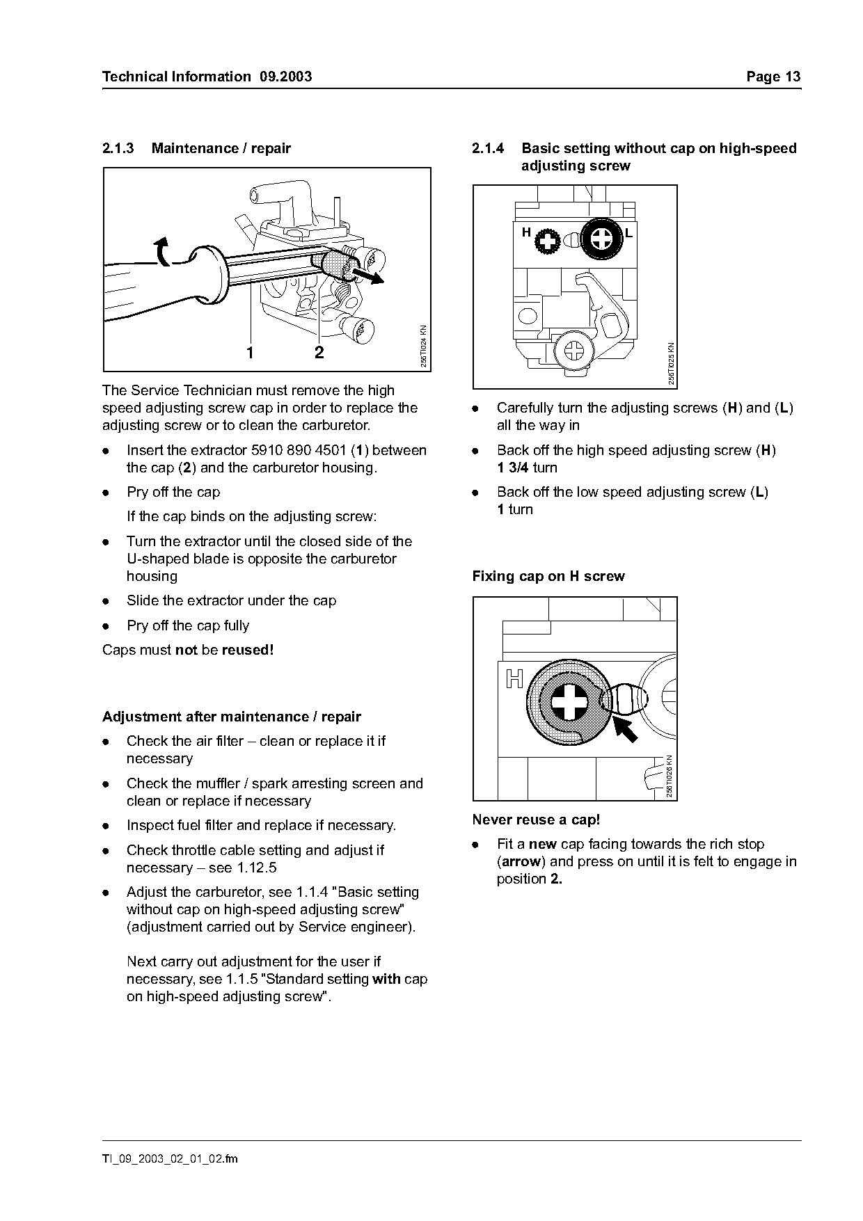
The Service Technician must remove the high
speed adjusting screw cap in order to replace the                   .   Carefully turn the adjusting screws (H) and (L)
adjusting screw or to clean the carburetor.                             all the way in
.   Insert the extractor 5910 890 4501 (1) between                  .   Back off the high speed adjusting screw (H)
    the cap (2) and the carburetor housing.                             1 3/4 turn
.   Pry off the cap                                                 .   Back off the low speed adjusting screw (L)
                                                                        1 turn
    If the cap binds on the adjusting screw:
.   Turn the extractor until the closed side of the
    U-shaped blade is opposite the carburetor
    housing                                                         Fixing cap on H screw
.   Slide the extractor under the cap
.   Pry off the cap fully
Caps must not be reused!

Adjustment after maintenance / repair
.   Check the air filter – clean or replace it if
    necessary
                                                                                                    256TI026 KN

.   Check the muffler / spark arresting screen and
    clean or replace if necessary
.   Inspect fuel filter and replace if necessary.                   Never reuse a cap!

.   Check throttle cable setting and adjust if                      .   Fit a new cap facing towards the rich stop
    necessary – see 1.12.5                                              (arrow) and press on until it is felt to engage in
                                                                        position 2.
.   Adjust the carburetor, see 1.1.4 "Basic setting
    without cap on high-speed adjusting screw"
    (adjustment carried out by Service engineer).

    Next carry out adjustment for the user if
    necessary, see 1.1.5 "Standard setting with cap
    on high-speed adjusting screw".

TI_09_2003_02_01_02.fm
Page 14 of 23
Text of page 14 — search, copy, screen readers
Page 14                                                                   Technical Information 09.2003

                                                        Speed varies when idling; engine stops when
                     a                                  swivelling machine to different position–
                                                        the idle setting is too rich!
                                                        .   Turn the low speed adjusting screw (L)
                                                            clockwise about 1/4 turn until the engine runs
                                                            uniformly and accelerates correctly

                                                        Whenever the low speed adjusting screw (L) has
                                                        been adjusted, an adjustment is usually required on
                               256TI027 KN

                                                        the idle speed adjusting screw (LA).

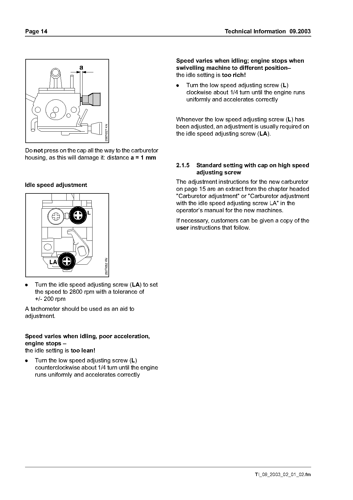
Do not press on the cap all the way to the carburetor
housing, as this will damage it: distance a = 1 mm
                                                        2.1.5   Standard setting with cap on high speed
                                                                adjusting screw
                                                        The adjustment instructions for the new carburetor
Idle speed adjustment
                                                        on page 15 are an extract from the chapter headed
                                                        "Carburetor adjustment" or "Carburetor adjustment
                                                        with the idle speed adjusting screw LA" in the
                         L                              operator’s manual for the new machines.
                                                        If necessary, customers can be given a copy of the
                                                        user instructions that follow.
                               250TI052 KN


.   Turn the idle speed adjusting screw (LA) to set
    the speed to 2800 rpm with a tolerance of
    +/- 200 rpm
A tachometer should be used as an aid to
adjustment.

Speed varies when idling, poor acceleration,
engine stops –
the idle setting is too lean!
.   Turn the low speed adjusting screw (L)
    counterclockwise about 1/4 turn until the engine
    runs uniformly and accelerates correctly

                                                                                      TI_09_2003_02_01_02.fm
Page 15 of 23
Text of page 15 — search, copy, screen readers
Technical Information 09.2003                                                                        Page 15

Carburetor adjustment                                   The standard setting should be used for metal
                                                        cutting tools or other attachments!
                                                        .   Carry out standard setting procedure
                                                        .   Let the engine warm up:
                                                            approx. 3 minutes if a mowing head is attached
                                                            approx. 5 minutes if a metal cutting tool or other
                                                            attachment is fitted
                                                        .   Open the throttle fully and in mountain country
              H
                   1                                        turn the high speed adjusting screw (H)
                                                            clockwise (= leaner) until the speed ceases to
                                                            increase. Maximum speed is normally reached
            LA                                              at the standard setting
                                                        Instructions for mountain country: a marginal
                                                        adjustment to the high speed adjusting screw of
                                    250BA039 KN

                                                        approx. 1/8 turn per 1,000 m (3,300 ft) may be
                                                        necessary.

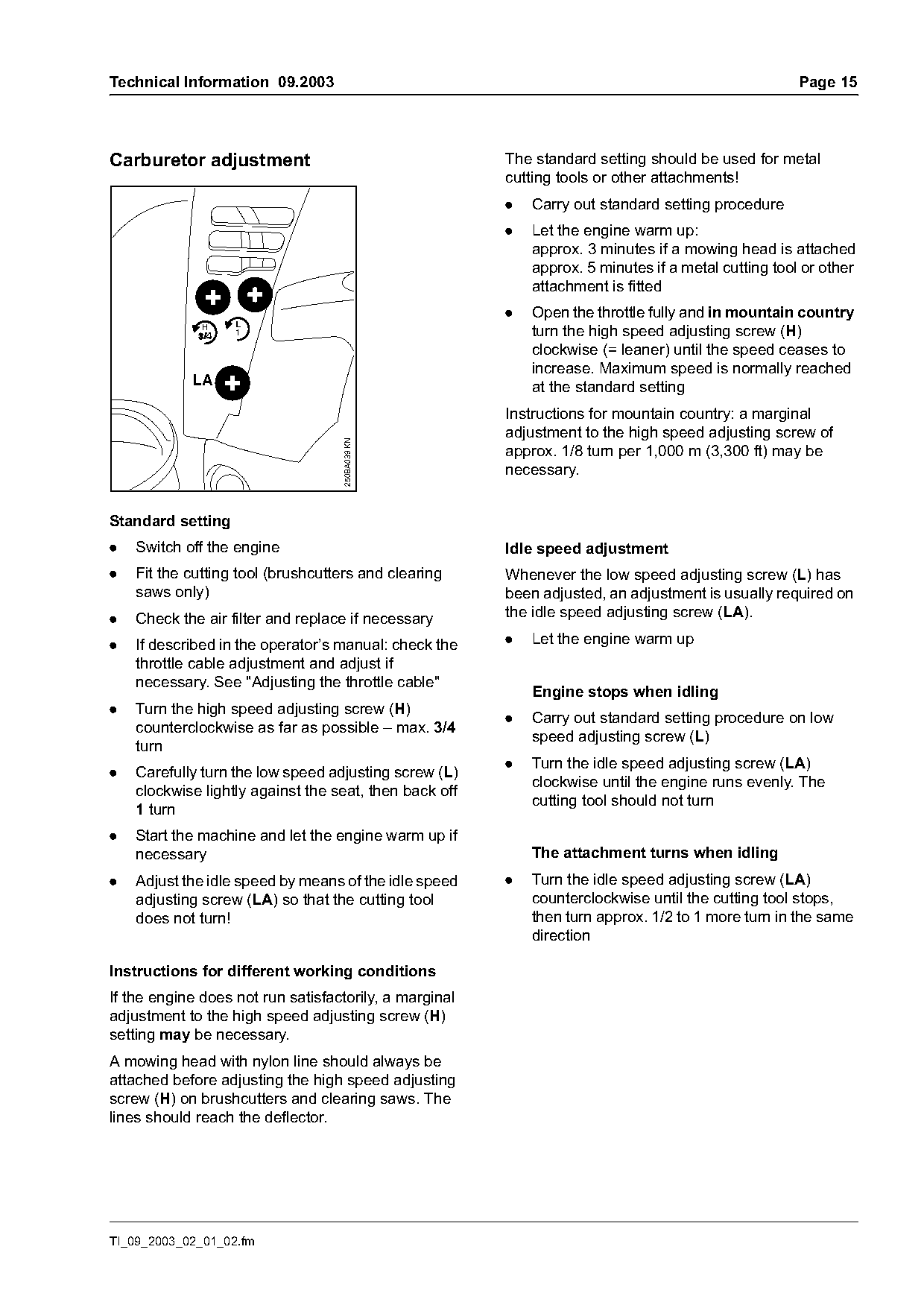
Standard setting
.   Switch off the engine                               Idle speed adjustment
.   Fit the cutting tool (brushcutters and clearing     Whenever the low speed adjusting screw (L) has
    saws only)                                          been adjusted, an adjustment is usually required on
.   Check the air filter and replace if necessary       the idle speed adjusting screw (LA).

.   If described in the operator’s manual: check the    .   Let the engine warm up
    throttle cable adjustment and adjust if
    necessary. See "Adjusting the throttle cable"
                                                            Engine stops when idling
.   Turn the high speed adjusting screw (H)
                                                        .   Carry out standard setting procedure on low
    counterclockwise as far as possible – max. 3/4
                                                            speed adjusting screw (L)
    turn
                                                        .   Turn the idle speed adjusting screw (LA)
.   Carefully turn the low speed adjusting screw (L)
                                                            clockwise until the engine runs evenly. The
    clockwise lightly against the seat, then back off
                                                            cutting tool should not turn
    1 turn
.   Start the machine and let the engine warm up if
    necessary                                               The attachment turns when idling
.   Adjust the idle speed by means of the idle speed    .   Turn the idle speed adjusting screw (LA)
    adjusting screw (LA) so that the cutting tool           counterclockwise until the cutting tool stops,
    does not turn!                                          then turn approx. 1/2 to 1 more turn in the same
                                                            direction

Instructions for different working conditions
If the engine does not run satisfactorily, a marginal
adjustment to the high speed adjusting screw (H)
setting may be necessary.
A mowing head with nylon line should always be
attached before adjusting the high speed adjusting
screw (H) on brushcutters and clearing saws. The
lines should reach the deflector.

TI_09_2003_02_01_02.fm
Page 16 of 23
Text of page 16 — search, copy, screen readers
Page 16                                                                              Technical Information 09.2003

2.1.6   Set of carburetor parts                                 2.4       Retrofitting existing machines
A new set of carburetor parts is required when                  The following existing parts have to be replaced by
carrying out repairs to the new carburetor. See 2.5             new versions in order to adapt the new carburetor in
"Summary".                                                      older machines:
                                                                –     carburetor assembly (see 2.1).
                                                                –     pin for attaching the throttle cable to the
                                                                      carburetor, see 2.4.1.
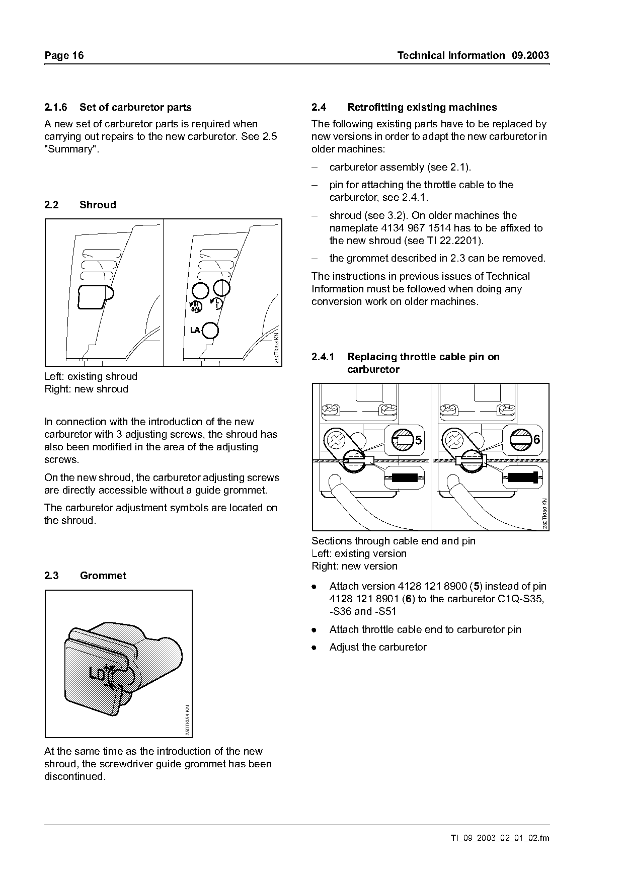
2.2     Shroud
                                                                –     shroud (see 3.2). On older machines the
                                                                      nameplate 4134 967 1514 has to be affixed to
                                                                      the new shroud (see TI 22.2201).
                                                                –     the grommet described in 2.3 can be removed.
                                                                The instructions in previous issues of Technical
                                                                Information must be followed when doing any
                                                                conversion work on older machines.
                                                  250TI053 KN

                                                                2.4.1     Replacing throttle cable pin on
                                                                          carburetor
Left: existing shroud
Right: new shroud

In connection with the introduction of the new
carburetor with 3 adjusting screws, the shroud has
                                                                                         5                          6
also been modified in the area of the adjusting
screws.
On the new shroud, the carburetor adjusting screws
are directly accessible without a guide grommet.

                                                                                                                        250TI050 KN
The carburetor adjustment symbols are located on
the shroud.
                                                                Sections through cable end and pin
                                                                Left: existing version
                                                                Right: new version
2.3     Grommet
                                                                .     Attach version 4128 121 8900 (5) instead of pin
                                                                      4128 121 8901 (6) to the carburetor C1Q-S35,
                                                                      -S36 and -S51
                                                                .     Attach throttle cable end to carburetor pin
                                                                .     Adjust the carburetor
                               250TI054 KN

At the same time as the introduction of the new
shroud, the screwdriver guide grommet has been
discontinued.

                                                                                                  TI_09_2003_02_01_02.fm
Page 17 of 23
Text of page 17 — search, copy, screen readers
Technical Information 09.2003                                                                        Page 17

2.4.2   Service notes                                    apply. Give the user a copy of the adjustment
After fitting a new carburetor to an older machine,      instructions in 2.1.5 (page 15) as the new
make the user aware that the carburetor adjustment       adjustment instructions.
instructions in the operator’s manual no longer

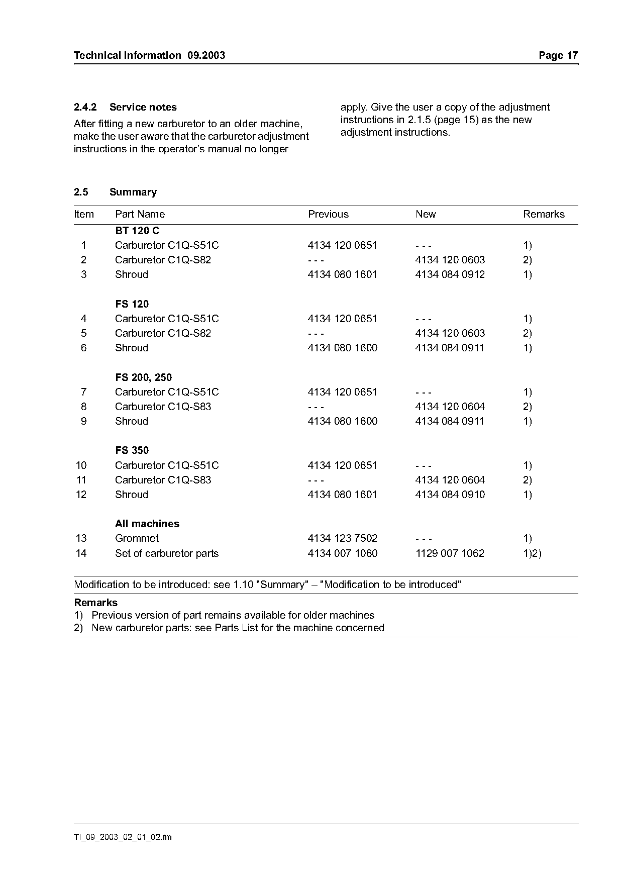
2.5     Summary

Item     Part Name                                Previous               New                    Remarks
         BT 120 C
 1       Carburetor C1Q-S51C                      4134 120 0651          ---                    1)
 2       Carburetor C1Q-S82                       ---                    4134 120 0603          2)
 3       Shroud                                   4134 080 1601          4134 084 0912          1)

         FS 120
 4       Carburetor C1Q-S51C                      4134 120 0651          ---                    1)
 5       Carburetor C1Q-S82                       ---                    4134 120 0603          2)
 6       Shroud                                   4134 080 1600          4134 084 0911          1)

         FS 200, 250
 7       Carburetor C1Q-S51C                      4134 120 0651          ---                    1)
 8       Carburetor C1Q-S83                       ---                    4134 120 0604          2)
 9       Shroud                                   4134 080 1600          4134 084 0911          1)

         FS 350
10       Carburetor C1Q-S51C                      4134 120 0651          ---                    1)
11       Carburetor C1Q-S83                       ---                    4134 120 0604          2)
12       Shroud                                   4134 080 1601          4134 084 0910          1)

         All machines
13       Grommet                                  4134 123 7502          ---                    1)
14       Set of carburetor parts                  4134 007 1060          1129 007 1062          1)2)

Modification to be introduced: see 1.10 "Summary" – "Modification to be introduced"
Remarks
1) Previous version of part remains available for older machines
2) New carburetor parts: see Parts List for the machine concerned

TI_09_2003_02_01_02.fm
Page 18 of 23
Text of page 18 — search, copy, screen readers
Page 18                                                                          Technical Information 09.2003

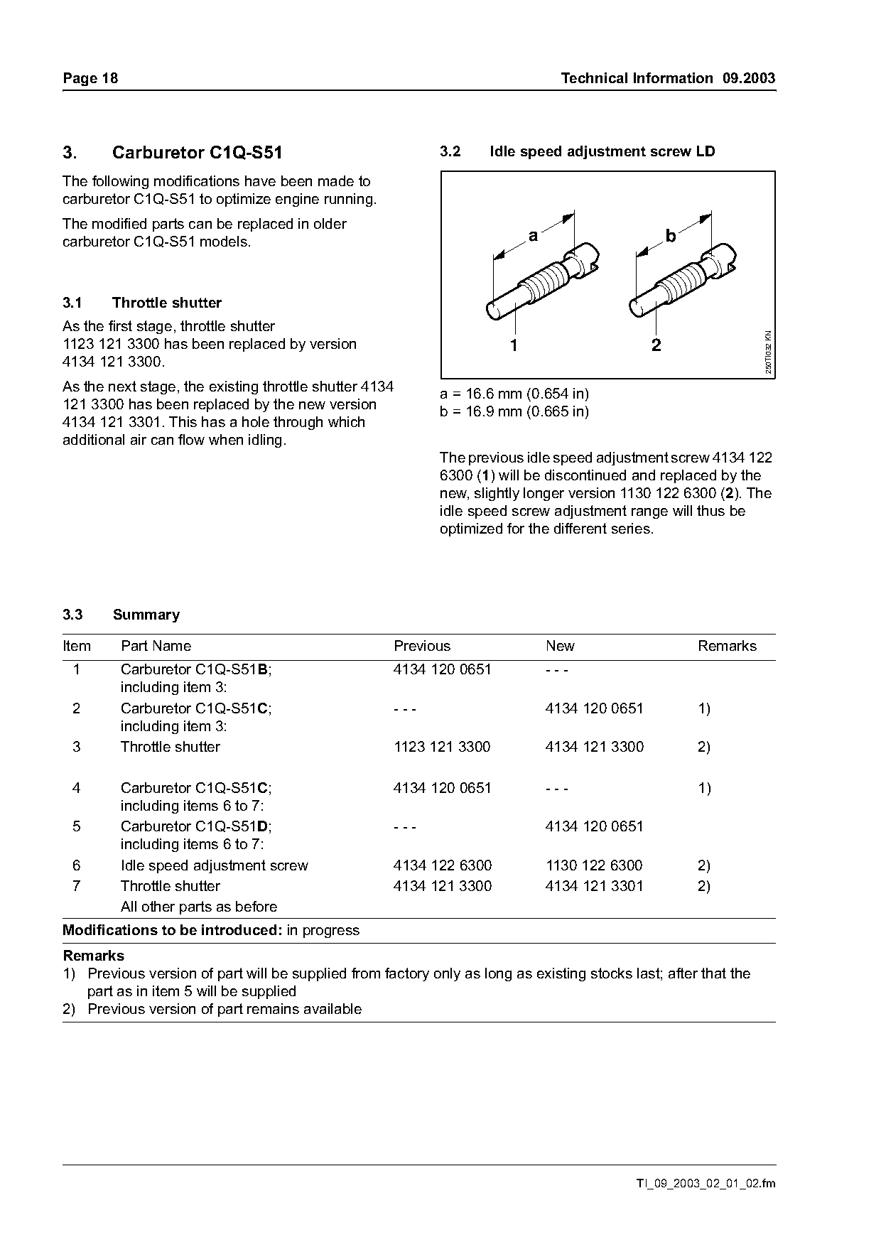
3.      Carburetor C1Q-S51                                  3.2     Idle speed adjustment screw LD

The following modifications have been made to
carburetor C1Q-S51 to optimize engine running.
The modified parts can be replaced in older
carburetor C1Q-S51 models.                                                 a                       b

3.1     Throttle shutter
As the first stage, throttle shutter

                                                                                                                 250TI032 KN
1123 121 3300 has been replaced by version                             1                       2
4134 121 3300.
As the next stage, the existing throttle shutter 4134       a = 16.6 mm (0.654 in)
121 3300 has been replaced by the new version               b = 16.9 mm (0.665 in)
4134 121 3301. This has a hole through which
additional air can flow when idling.
                                                            The previous idle speed adjustment screw 4134 122
                                                            6300 (1) will be discontinued and replaced by the
                                                            new, slightly longer version 1130 122 6300 (2). The
                                                            idle speed screw adjustment range will thus be
                                                            optimized for the different series.

3.3     Summary

Item      Part Name                                 Previous                   New                     Remarks
 1        Carburetor C1Q-S51B;                      4134 120 0651              ---
          including item 3:
 2        Carburetor C1Q-S51C;                      ---                        4134 120 0651           1)
          including item 3:
 3        Throttle shutter                          1123 121 3300              4134 121 3300           2)

 4        Carburetor C1Q-S51C;                      4134 120 0651              ---                     1)
          including items 6 to 7:
 5        Carburetor C1Q-S51D;                      ---                        4134 120 0651
          including items 6 to 7:
 6        Idle speed adjustment screw               4134 122 6300              1130 122 6300           2)
 7        Throttle shutter                          4134 121 3300              4134 121 3301           2)
          All other parts as before
Modifications to be introduced: in progress
Remarks
1) Previous version of part will be supplied from factory only as long as existing stocks last; after that the
   part as in item 5 will be supplied
2) Previous version of part remains available

                                                                                           TI_09_2003_02_01_02.fm
Page 19 of 23
Text of page 19 — search, copy, screen readers
Technical Information 09.2003                                                                                    Page 19

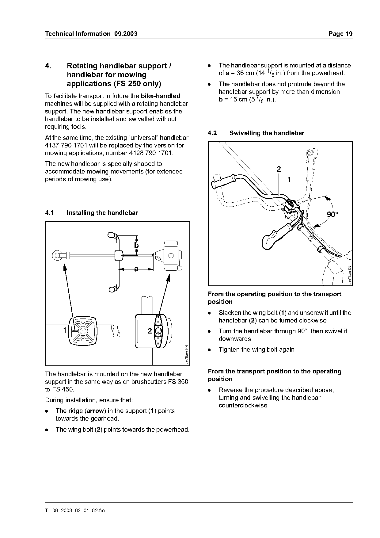
4.       Rotating handlebar support /                             .     The handlebar support is mounted at a distance
         handlebar for mowing                                           of a = 36 cm (14 1/8 in.) from the powerhead.
         applications (FS 250 only)                               .     The handlebar does not protrude beyond the
                                                                        handlebar support by more than dimension
To facilitate transport in future the bike-handled
                                                                        b = 15 cm (5 7/8 in.).
machines will be supplied with a rotating handlebar
support. The new handlebar support enables the
handlebar to be installed and swivelled without
requiring tools.
                                                                  4.2       Swivelling the handlebar
At the same time, the existing "universal" handlebar
4137 790 1701 will be replaced by the version for
mowing applications, number 4128 790 1701.
The new handlebar is specially shaped to
accommodate mowing movements (for extended                                                   2
periods of mowing use).                                                                          1

4.1      Installing the handlebar                                                                               90°


                                                                                                                         249TI038 KN
                                                                  From the operating position to the transport
                                                                  position
                                                                  .     Slacken the wing bolt (1) and unscrew it until the
                                                                        handlebar (2) can be turned clockwise
        1                               2                         .     Turn the handlebar through 90°, then swivel it
                                                                        downwards
                                                    250TI056 KN

                                                                  .     Tighten the wing bolt again

The handlebar is mounted on the new handlebar                     From the transport position to the operating
support in the same way as on brushcutters FS 350                 position
to FS 450.                                                        .     Reverse the procedure described above,
During installation, ensure that:                                       turning and swivelling the handlebar
                                                                        counterclockwise
.     The ridge (arrow) in the support (1) points
      towards the gearhead.
.     The wing bolt (2) points towards the powerhead.

TI_09_2003_02_01_02.fm
Page 20 of 23
Text of page 20 — search, copy, screen readers
Page 20                                                                   Technical Information 09.2003

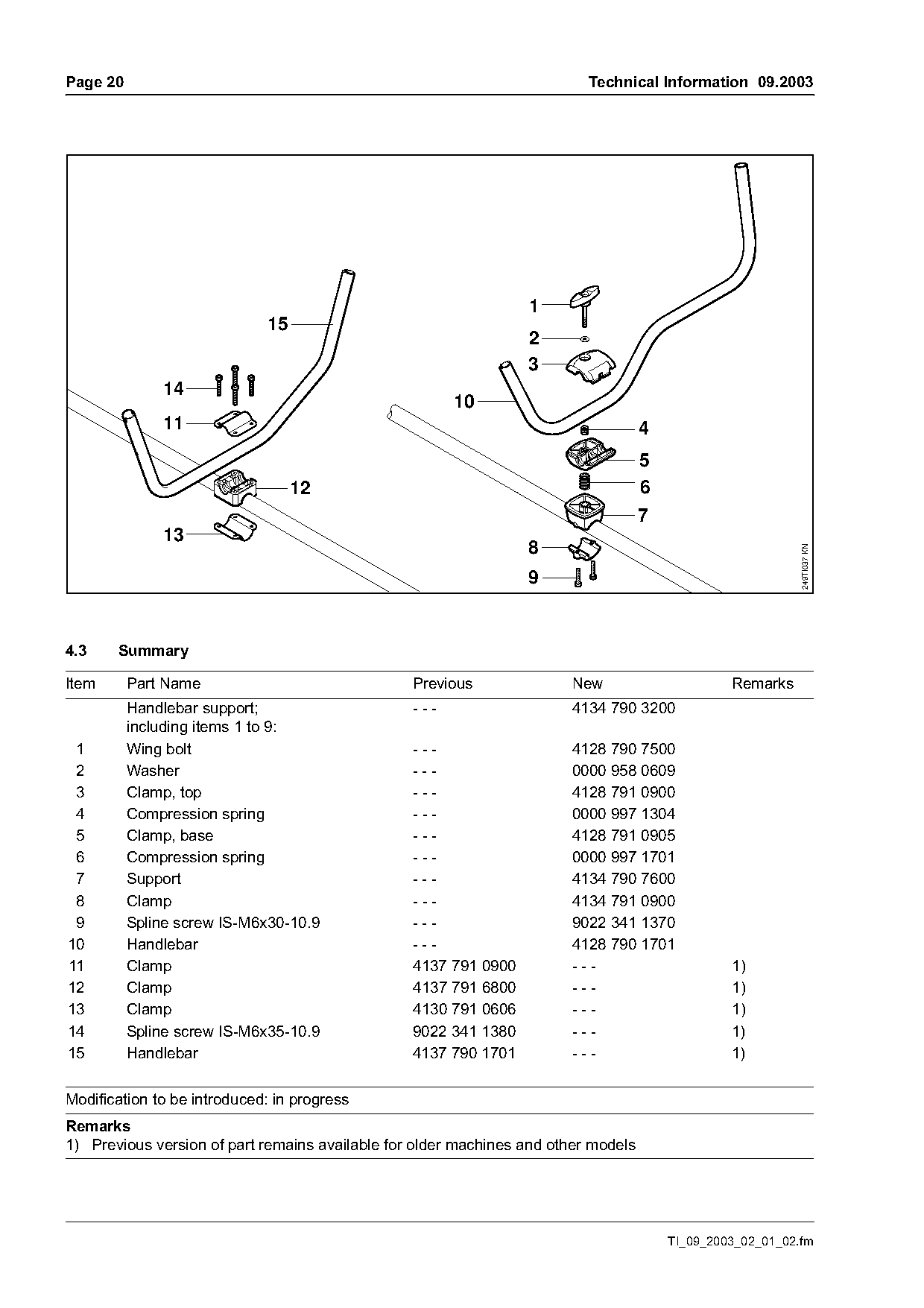
                                                                 1
                             15
                                                                 2
                                                                 3
              14
                                                       10
              11                                                                    4
                                                                                    5
                                  12                                                6
                                                                                    7
              13
                                                                 8

                                                                                                            249TI037 KN
                                                                 9

4.3    Summary

Item      Part Name                              Previous              New                       Remarks
          Handlebar support;                     ---                   4134 790 3200
          including items 1 to 9:
 1        Wing bolt                              ---                   4128 790 7500
 2        Washer                                 ---                   0000 958 0609
 3        Clamp, top                             ---                   4128 791 0900
 4        Compression spring                     ---                   0000 997 1304
 5        Clamp, base                            ---                   4128 791 0905
 6        Compression spring                     ---                   0000 997 1701
 7        Support                                ---                   4134 790 7600
 8        Clamp                                  ---                   4134 791 0900
 9        Spline screw IS-M6x30-10.9             ---                   9022 341 1370
10        Handlebar                              ---                   4128 790 1701
11        Clamp                                  4137 791 0900         ---                       1)
12        Clamp                                  4137 791 6800         ---                       1)
13        Clamp                                  4130 791 0606         ---                       1)
14        Spline screw IS-M6x35-10.9             9022 341 1380         ---                       1)
15        Handlebar                              4137 790 1701         ---                       1)

Modification to be introduced: in progress
Remarks
1) Previous version of part remains available for older machines and other models

                                                                                        TI_09_2003_02_01_02.fm
Page 21 of 23
Text of page 21 — search, copy, screen readers
Technical Information 09.2003                                                                                    Page 21

5.     Clutch
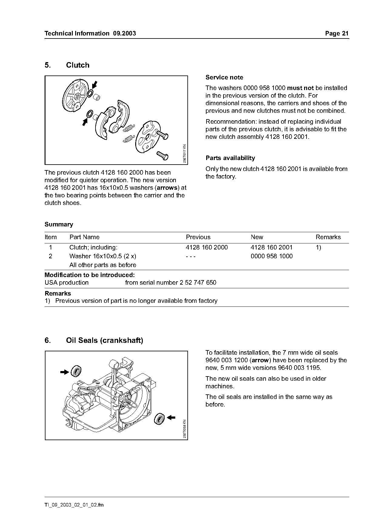
                                                                 Service note
                                                                 The washers 0000 958 1000 must not be installed
                                                                 in the previous version of the clutch. For
                                                                 dimensional reasons, the carriers and shoes of the
                                                                 previous and new clutches must not be combined.
                                                                 Recommendation: instead of replacing individual
                                                                 parts of the previous clutch, it is advisable to fit the
                                                                 new clutch assembly 4128 160 2001.

                                                  256TI017 KN
                                                                 Parts availability
                                                                 Only the new clutch 4128 160 2001 is available from
The previous clutch 4128 160 2000 has been
                                                                 the factory.
modified for quieter operation. The new version
4128 160 2001 has 16x10x0.5 washers (arrows) at
the two bearing points between the carrier and the
clutch shoes.

Summary

Item     Part Name                                         Previous               New                       Remarks
 1       Clutch; including:                                4128 160 2000          4128 160 2001             1)
 2       Washer 16x10x0.5 (2 x)                            ---                    0000 958 1000
         All other parts as before
Modification to be introduced:
USA production             from serial number 2 52 747 650
Remarks
1) Previous version of part is no longer available from factory

6.     Oil Seals (crankshaft)
                                                                 To facilitate installation, the 7 mm wide oil seals
                                                                 9640 003 1200 (arrow) have been replaced by the
                                                                 new, 5 mm wide versions 9640 003 1195.
                                                                 The new oil seals can also be used in older
                                                                 machines.
                                                                 The oil seals are installed in the same way as
                                                                 before.
                                                  250TI058 KN

TI_09_2003_02_01_02.fm
Page 22 of 23
Text of page 22 — search, copy, screen readers
Page 22                                                                              Technical Information 09.2003

Summary

Item      Part Name                                        Previous               New                       Remarks
 1        Oil seal DIN3760-BS12x22x7                       9640 003 1200          ---                       1)
 2        Oil seal DIN3760-BS12x22x5                       ---                    9640 003 1195
Modification to be introduced in progress
Remarks
1) Previous version of part is no longer available from factory

7.     Crankshaft
       (FS 120, 200, 250, BT 120 only)
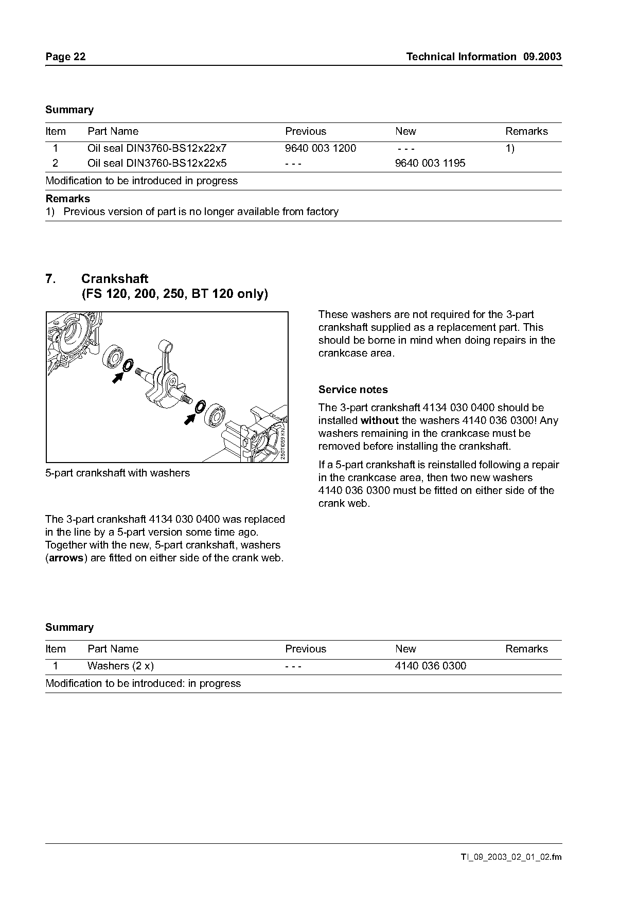
                                                                 These washers are not required for the 3-part
                                                                 crankshaft supplied as a replacement part. This
                                                                 should be borne in mind when doing repairs in the
                                                                 crankcase area.

                                                                 Service notes
                                                                 The 3-part crankshaft 4134 030 0400 should be
                                                                 installed without the washers 4140 036 0300! Any
                                                                 washers remaining in the crankcase must be
                                                  250TI059 KN

                                                                 removed before installing the crankshaft.
                                                                 If a 5-part crankshaft is reinstalled following a repair
5-part crankshaft with washers                                   in the crankcase area, then two new washers
                                                                 4140 036 0300 must be fitted on either side of the
                                                                 crank web.
The 3-part crankshaft 4134 030 0400 was replaced
in the line by a 5-part version some time ago.
Together with the new, 5-part crankshaft, washers
(arrows) are fitted on either side of the crank web.

Summary

Item      Part Name                                        Previous               New                       Remarks
 1        Washers (2 x)                                    ---                    4140 036 0300
Modification to be introduced: in progress

                                                                                                  TI_09_2003_02_01_02.fm
Page 23 of 23
Text of page 23 — search, copy, screen readers
Technical Information 09.2003                                                         Page 23

8.     Rewind Starter / Spring Housing
       Fastening
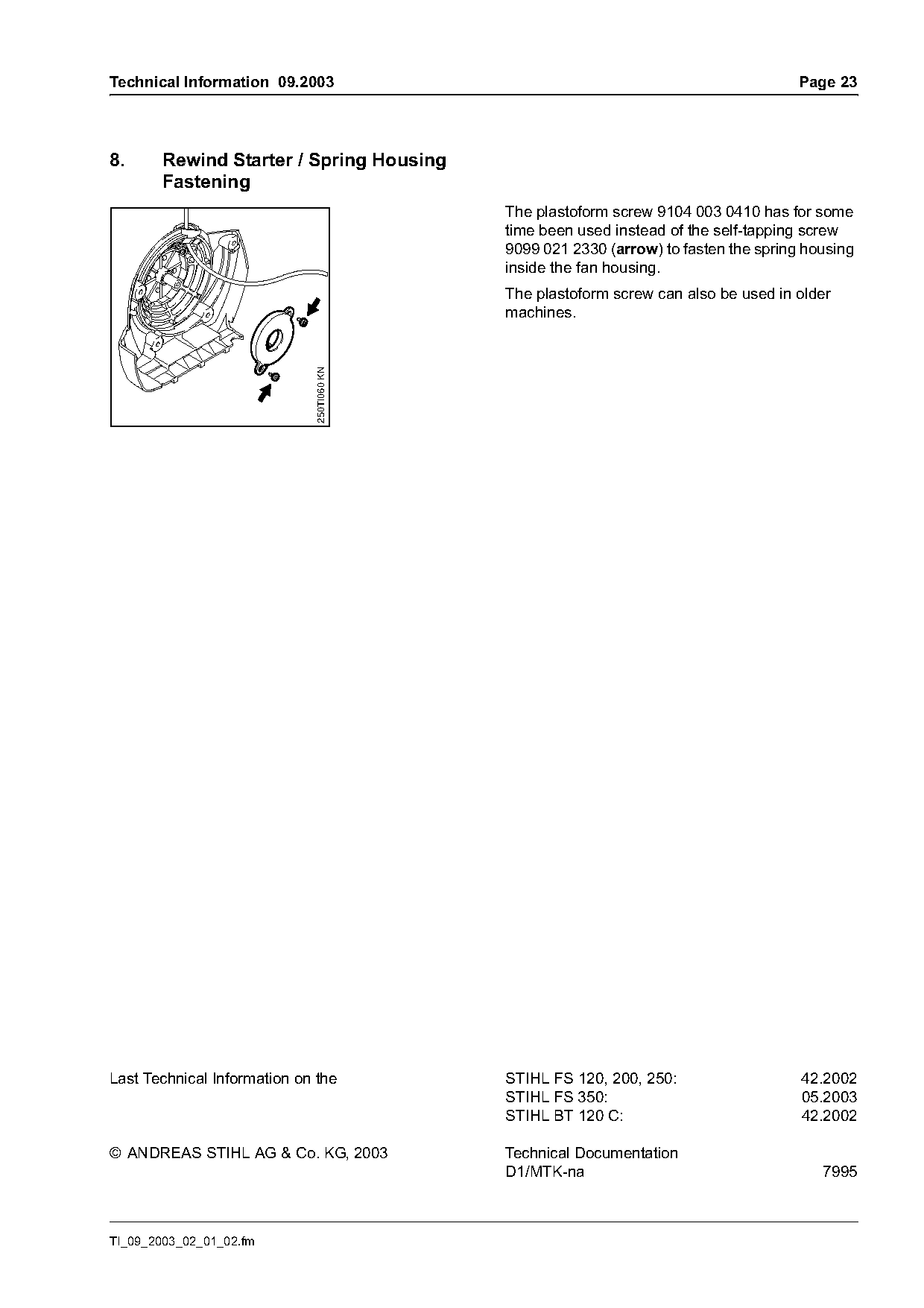
                                            The plastoform screw 9104 003 0410 has for some
                                            time been used instead of the self-tapping screw
                                            9099 021 2330 (arrow) to fasten the spring housing
                                            inside the fan housing.
                                            The plastoform screw can also be used in older
                              250TI060 KN
                                            machines.

Last Technical Information on the           STIHL FS 120, 200, 250:                   42.2002
                                            STIHL FS 350:                             05.2003
                                            STIHL BT 120 C:                           42.2002

© ANDREAS STIHL AG & Co. KG, 2003           Technical Documentation
                                            D1/MTK-na                                    7995

TI_09_2003_02_01_02.fm
Most of these PDFs embed fonts with a shifted character map, so the text above was recovered rather than copied — read it as a faithful but imperfect transcription, and treat the page image above each block as the authority where the two disagree — the figures exist only there, because they are vector drawings that text extraction cannot keep.