Technical Information · issue 15 of 2003
Carburetor; Cylinder gasket; Oil seals (crankshaft); Rotating handle holder / mowing handle (FS 80, FS 85, KM 85); Engine mounting (FR 85, FR 85 T, HLR 85, HTR 85); Solid shaft (FS 85); Clamps / handle (torque, only for machines with wraparound h
IssueTI 15/2003
Full text
Page 1 of 8
Text of page 1 — search, copy, screen readers
STIH)

Technical Information

                                                                              15.2003

  STIHL FH 75 power scythe                                                – Series 4230

  STIHL HL 75 hedge trimmer                                               – Series 4230
  STIHL HT 70, HT 75 pole pruners                                         – Series 4138
  STIHL FC 75, FC 85 edger                                fo              – Series 4137
  STIHL KW 85 PowerSweep                                                  – Series 4602
  STIHL KM 85 KombiEngine                                                 – Series 4137
  STIHL FS 75, FS 80, FS 85 brushcutters                                  – Series 4137

  Contents
  1. Carburetor

     1.1 Features of the new carburetor

     1.2 Mechanical design
     1.3 Functions of the cap on the high speed adjusting screw
     1.4 Flange, seal and metering diaphragm
     1.5 Set of carburetor parts

     1.6 Maintenance / repair
     1.7 Summary

  2. Cylinder gasket
     2.1 Service note
     2.2 Note for blowers and hedge trimmers

     2.3 Summary
  3. Oil seals (crankshaft)
  4. Clamps / handle (torque, only for machines with wraparound handle)

  TI_15_2003_02_01_01.fm                                                        englisch / English USA
Page 2 of 8
Text of page 2 — search, copy, screen readers
Page 2                                                                                Technical Information 15.2003

1.       Carburetor                                               1.2      Mechanical design

                                                                          5
                                                                                                                1
                                                                                                                2
                                                                                                                    3

                                                                                                                        233TI021 KN
                                                    233TI020 KN


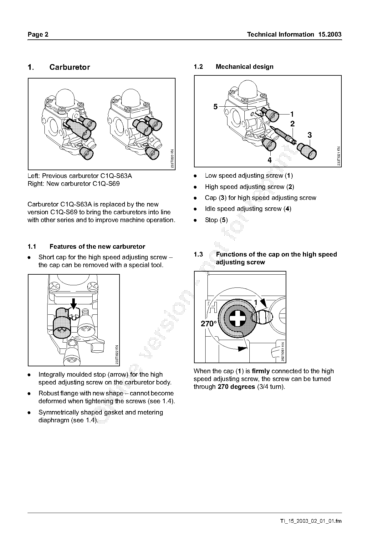
Left: Previous carburetor C1Q-S63A                                .     Low speed adjusting screw (1)
Right: New carburetor C1Q-S69

                                                                  .     High speed adjusting screw (2)
                                                                  .     Cap (3) for high speed adjusting screw
Carburetor C1Q-S63A is replaced by the new

                                                                  .     Idle speed adjusting screw (4)
version C1Q-S69 to bring the carburetors into line
with other series and to improve machine operation.               .     Stop (5)
1.1      Features of the new carburetor
.     Short cap for the high speed adjusting screw –              1.3      Functions of the cap on the high speed
      the cap can be removed with a special tool.                          adjusting screw


                                                                      270°

                                                                                                  392TI061 KN
                                233TI022 KN

.     Integrally moulded stop (arrow) for the high                When the cap (1) is firmly connected to the high
      speed adjusting screw on the carburetor body.               speed adjusting screw, the screw can be turned

                                                                  through 270 degrees (3/4 turn).
.     Robust flange with new shape – cannot become
      deformed when tightening the screws (see 1.4).

.     Symmetrically shaped gasket and metering
      diaphragm (see 1.4).

                                                                                                  TI_15_2003_02_01_01.fm
Page 3 of 8
Text of page 3 — search, copy, screen readers
Technical Information 15.2003                                                                                   Page 3

1.4     Flange, seal and metering diaphragm
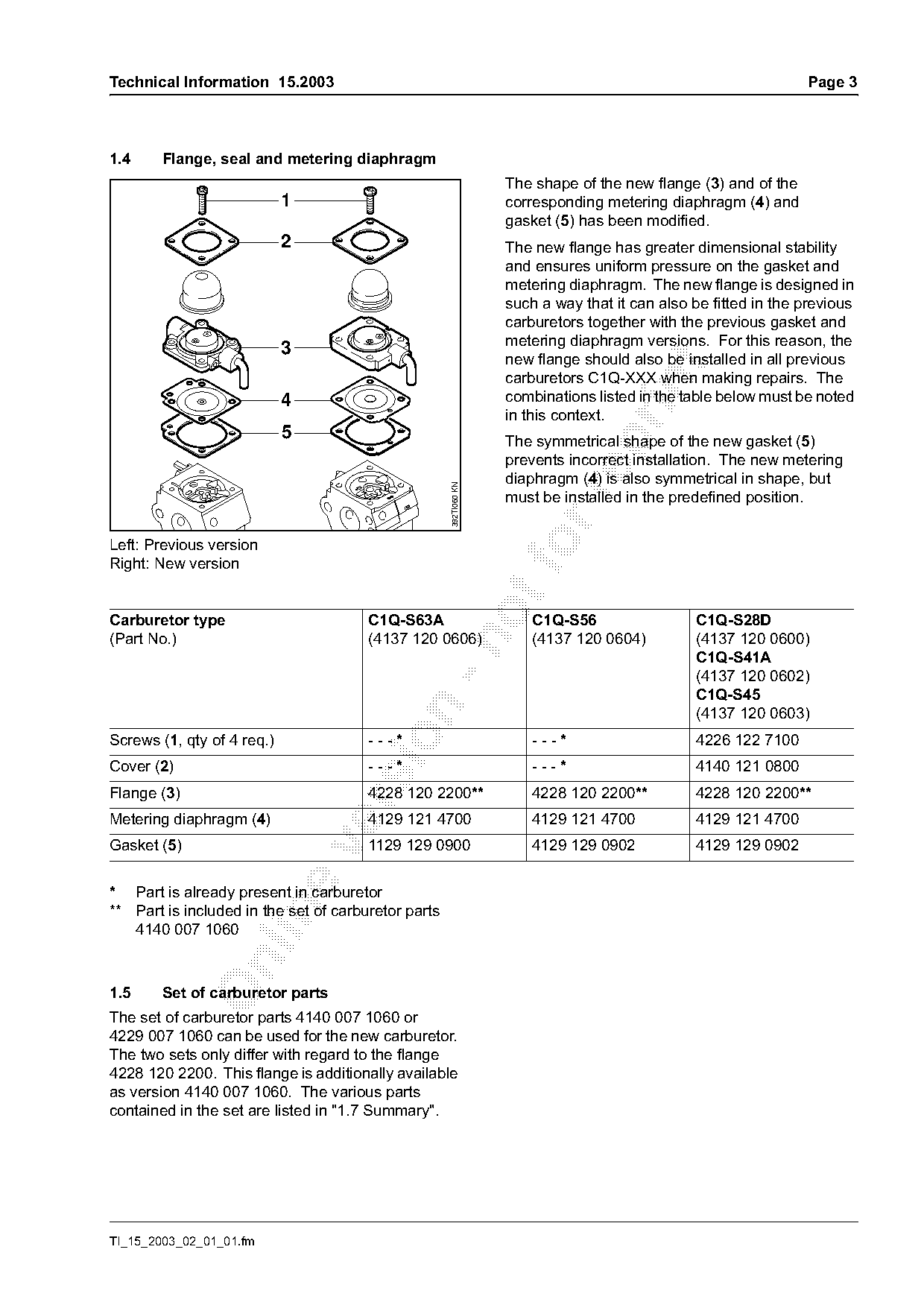
                                                                   The shape of the new flange (3) and of the
                            1                                      corresponding metering diaphragm (4) and
                                                                   gasket (5) has been modified.
                            2                                      The new flange has greater dimensional stability
                                                                   and ensures uniform pressure on the gasket and
                                                                   metering diaphragm. The new flange is designed in
                                                                   such a way that it can also be fitted in the previous
                                                                   carburetors together with the previous gasket and
                                                                   metering diaphragm versions. For this reason, the
                            3
                                                                   new flange should also be installed in all previous

                                                                   carburetors C1Q-XXX when making repairs. The

                            4                                      combinations listed in the table below must be noted
                                                                   in this context.
                            5                                      The symmetrical shape of the new gasket (5)

                                                                   prevents incorrect installation. The new metering
                                                                   diaphragm (4) is also symmetrical in shape, but
                                                     392TI060 KN

                                                                   must be installed in the predefined position.

Left: Previous version
Right: New version
Carburetor type                        C1Q-S63A                        C1Q-S56                 C1Q-S28D
(Part No.)                             (4137 120 0606)                 (4137 120 0604)         (4137 120 0600)

                                                                                               C1Q-S41A
                                                                                               (4137 120 0602)
                                                                                               C1Q-S45

                                                                                               (4137 120 0603)

Screws (1, qty of 4 req.)              ---*                            ---*                    4226 122 7100
Cover (2)                              ---*                            ---*                    4140 121 0800
Flange (3)                             4228 120 2200**                 4228 120 2200**         4228 120 2200**

Metering diaphragm (4)                 4129 121 4700                   4129 121 4700           4129 121 4700
Gasket (5)                             1129 129 0900                   4129 129 0902           4129 129 0902

* Part is already present in carburetor
** Part is included in the set of carburetor parts

   4140 007 1060

1.5     Set of carburetor parts
The set of carburetor parts 4140 007 1060 or
4229 007 1060 can be used for the new carburetor.
The two sets only differ with regard to the flange
4228 120 2200. This flange is additionally available
as version 4140 007 1060. The various parts
contained in the set are listed in "1.7 Summary".

TI_15_2003_02_01_01.fm
Page 4 of 8
Text of page 4 — search, copy, screen readers
Page 4                                                                                   Technical Information 15.2003

1.6       Maintenance / repair                                        .   Set the carburetor, see 1.6.1 "Basic setting
                                                                          without cap on the high speed adjusting
                                                                          screw".

                                                                          Then make the adjustment for the user if
                                                                          necessary, see also 1.6.2.

                                                                      1.6.1   Basic setting without cap on the high
                                                                              speed adjusting screw

                                                        256TI024 KN

                          1           2

The cap must be removed from the high speed                                   H                L
adjusting screw to replace a defective high speed

adjusting screw or to clean the carburetor:
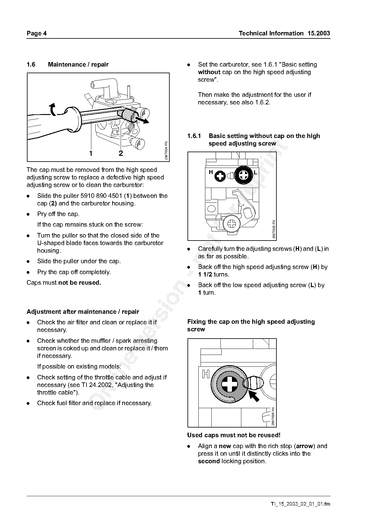
.     Slide the puller 5910 890 4501 (1) between the

      cap (2) and the carburetor housing.
.     Pry off the cap.

                                                                                                        256TI025 KN
      If the cap remains stuck on the screw:
.     Turn the puller so that the closed side of the
      U-shaped blade faces towards the carburetor
      housing.                                                        .   Carefully turn the adjusting screws (H) and (L) in
                                                                          as far as possible.

.     Slide the puller under the cap.
                                                                      .   Back off the high speed adjusting screw (H) by
.     Pry the cap off completely.                                         1 1/2 turns.
Caps must not be reused.                                              .   Back off the low speed adjusting screw (L) by

                                                                          1 turn.

Adjustment after maintenance / repair
.     Check the air filter and clean or replace it if                 Fixing the cap on the high speed adjusting

      necessary.                                                      screw
.     Check whether the muffler / spark arresting

      screen is coked up and clean or replace it / them
      if necessary.
      If possible on existing models:

.     Check setting of the throttle cable and adjust if
      necessary (see TI 24.2002, "Adjusting the

      throttle cable").
.     Check fuel filter and replace if necessary.
                                                                                                      256TI026 KN

                                                                      Used caps must not be reused!
                                                                      .   Align a new cap with the rich stop (arrow) and
                                                                          press it on until it distinctly clicks into the
                                                                          second locking position.

                                                                                                     TI_15_2003_02_01_01.fm
Page 5 of 8
Text of page 5 — search, copy, screen readers
Technical Information 15.2003                                                                              Page 5

                                                                   Machine runs erratically when idling,
                         a                                         poor acceleration, engine stops –
                                                                   the low speed setting is too lean.
                                                              .    Turn the low speed adjusting screw (L) approx.
                                                                   1/4 turn counterclockwise until the engine runs
                                                                   uniformly and accelerates well.

                                                                   Machine runs erratically when idling,
                                                                   engine stops when swivelling –
                                   256TI027 KN

                                                                   the low speed setting is too rich.

                                                              .    Turn the low speed adjusting screw (L) approx.

Do not press the cap on until it rests on the                      1/4 turn clockwise until the engine runs
carburetor housing, otherwise it will be damaged:                  uniformly and accelerates well.
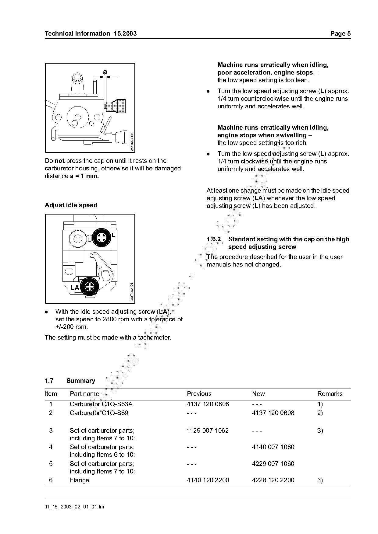
distance a = 1 mm.

                                                              At least one change must be made on the idle speed
                                                              adjusting screw (LA) whenever the low speed

Adjust idle speed                                             adjusting screw (L) has been adjusted.

                                                              1.6.2   Standard setting with the cap on the high
                                                                      speed adjusting screw
                                                              The procedure described for the user in the user

                                                              manuals has not changed.
                                   250TI052 KN


.       With the idle speed adjusting screw (LA),
        set the speed to 2800 rpm with a tolerance of
        +/-200 rpm.

The setting must be made with a tachometer.

1.7        Summary

Item         Part name                                  Previous               New                    Remarks
    1        Carburetor C1Q-S63A                        4137 120 0606          ---                    1)
    2        Carburetor C1Q-S69                         ---                    4137 120 0608          2)

    3        Set of carburetor parts;                   1129 007 1062          ---                    3)
             including Items 7 to 10:
    4        Set of carburetor parts;                   ---                    4140 007 1060
             including Items 6 to 10:
    5        Set of carburetor parts;                   ---                    4229 007 1060
             including Items 7 to 10:
    6        Flange                                     4140 120 2200          4228 120 2200          3)

TI_15_2003_02_01_01.fm
Page 6 of 8
Text of page 6 — search, copy, screen readers
Page 6                                                                              Technical Information 15.2003

Item     Part name                                         Previous               New                    Remarks
 7       Gasket                                            1129 129 0900          4229 129 0901          3)
 8       Metering diaphragm                                4129 121 4700          4229 121 4700          3)
 9       Pump diaphragm                                    1129 121 4800          1129 121 4800          3)
10       Gasket                                            1123 129 0905          1123 129 0905          3)
Changes to be introduced
Production USA      FS 80                      as from serial No. 2 61 042 486
                    HT 75                      as from serial No. 2 61 045 094
                    continuously in all other series
Remarks

1) Previous version of part is no longer available

2) Individual parts of the new carburetor: see spare parts list for the machine concerned
3) Previous version of part remains available

2.       Cylinder gasket                                         2.1
                                                                        Service note

                                                                                                                   392TI059 KN
                                                   392TI058 KN

             1                        2                                       3                      4

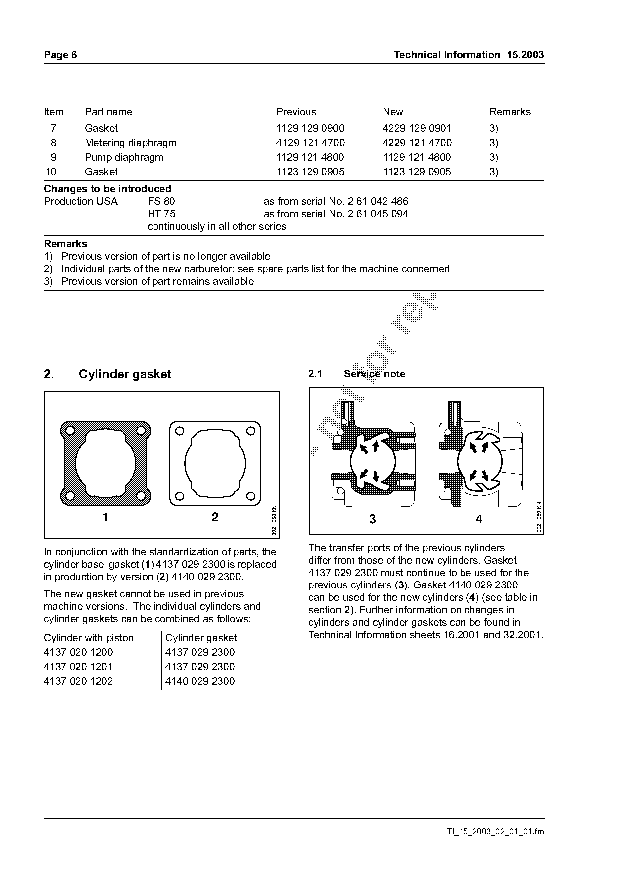
In conjunction with the standardization of parts, the            The transfer ports of the previous cylinders
cylinder base gasket (1) 4137 029 2300 is replaced               differ from those of the new cylinders. Gasket

in production by version (2) 4140 029 2300.                      4137 029 2300 must continue to be used for the
                                                                 previous cylinders (3). Gasket 4140 029 2300
The new gasket cannot be used in previous                        can be used for the new cylinders (4) (see table in
machine versions. The individual cylinders and                   section 2). Further information on changes in

cylinder gaskets can be combined as follows:                     cylinders and cylinder gaskets can be found in
Cylinder with piston       Cylinder gasket                       Technical Information sheets 16.2001 and 32.2001.

4137 020 1200              4137 029 2300
4137 020 1201              4137 029 2300
4137 020 1202              4140 029 2300

                                                                                              TI_15_2003_02_01_01.fm
Page 7 of 8
Text of page 7 — search, copy, screen readers
Technical Information 15.2003                                                                                 Page 7

2.2     Note for blowers and hedge trimmers
Only the cylinders with piston 4137 020 1200 and
1201 have been installed in the models BG 75,
HS 75, 80 and 85.

2.3     Summary

Item     Part name                                        Previous               New                     Remarks

 1       Cylinder gasket                                  4137 029 2300          4140 029 2300           1)

Modification introduced in progress
Remarks
1) Previous version of part remains available

3.     Oil seals (crankshaft)
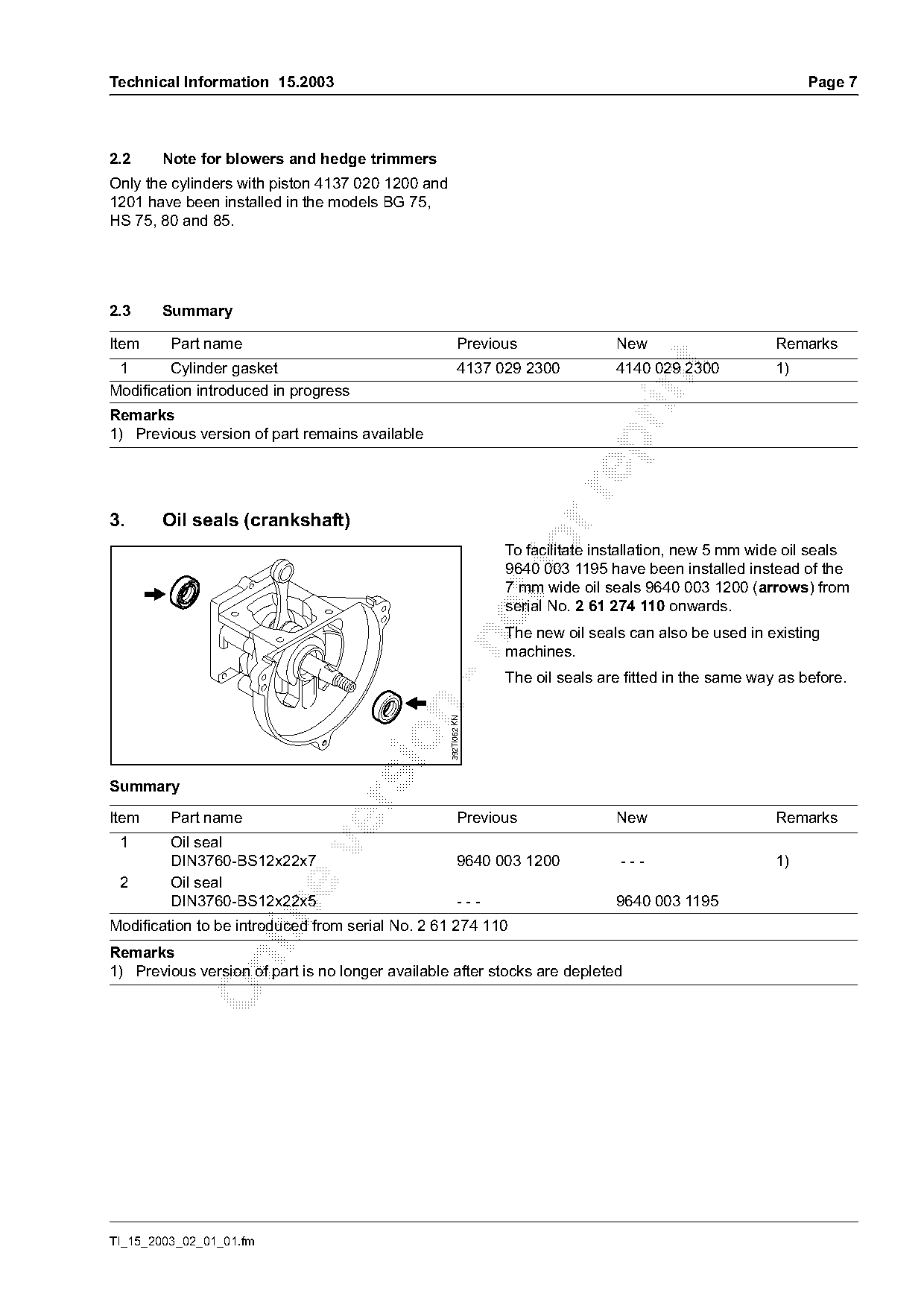
                                                                 To facilitate installation, new 5 mm wide oil seals
                                                                 9640 003 1195 have been installed instead of the
                                                                 7 mm wide oil seals 9640 003 1200 (arrows) from
                                                                 serial No. 2 61 274 110 onwards.
                                                                 The new oil seals can also be used in existing

                                                                 machines.
                                                                 The oil seals are fitted in the same way as before.
                                            n      392TI062 KN

Summary

Item     Part name                                        Previous               New                     Remarks
 1       Oil seal

         DIN3760-BS12x22x7                                9640 003 1200           ---                    1)
 2       Oil seal
         DIN3760-BS12x22x5                                ---                    9640 003 1195

Modification to be introduced from serial No. 2 61 274 110
Remarks

1) Previous version of part is no longer available after stocks are depleted

TI_15_2003_02_01_01.fm
Page 8 of 8
Text of page 8 — search, copy, screen readers
Page 8                                                                         Technical Information 15.2003

4.       Clamps / handle
         (torque, only for machines with
         wraparound handle)

                  2
              1

                                                392TI057 KN
                                   2
                               1

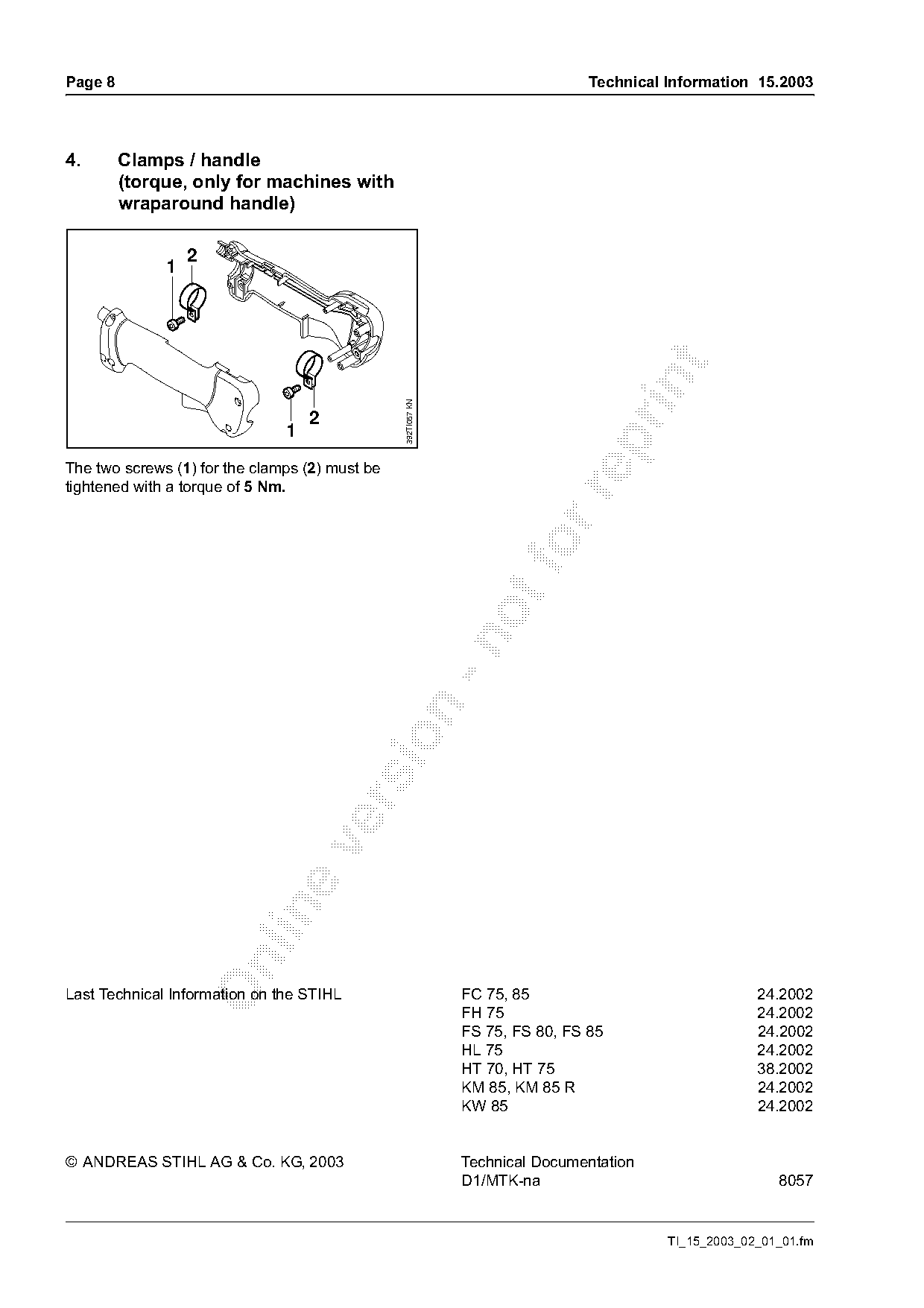
The two screws (1) for the clamps (2) must be
tightened with a torque of 5 Nm.

Last Technical Information on the STIHL                       FC 75, 85                               24.2002
                                                              FH 75                                   24.2002
                                                              FS 75, FS 80, FS 85                     24.2002
                                                              HL 75                                   24.2002
                                                              HT 70, HT 75                            38.2002
                                                              KM 85, KM 85 R                          24.2002
                                                              KW 85                                   24.2002

© ANDREAS STIHL AG & Co. KG, 2003                             Technical Documentation
                                                              D1/MTK-na                                  8057

                                                                                         TI_15_2003_02_01_01.fm
Most of these PDFs embed fonts with a shifted character map, so the text above was recovered rather than copied — read it as a faithful but imperfect transcription, and treat the page image above each block as the authority where the two disagree — the figures exist only there, because they are vector drawings that text extraction cannot keep.