Technical Information · issue 16 of 2003
Gearhead (shaft bearing); Hook; Forkhead; Circlip
IssueTI 16/2003
Full text
Page 1 of 8
Text of page 1 — search, copy, screen readers
STIH)

Technical Information

                                                                                       16.2003

  SP 400, SP 450 Special Harvester – Series 4234

  Contents
  1.
  2.
       Gearhead (shaft bearing)
       Hook
  3.   Forkhead
  4.   Circlip for Carrying Ring
  5.   Ignition Module (cut-off speed)

  6.   Oil Seal (crankshaft)
  7.   Clutch Drum
  8.   Screws (gearhead / frame)
  9.   Tightening Torques

  1.    Gearhead (shaft bearing)

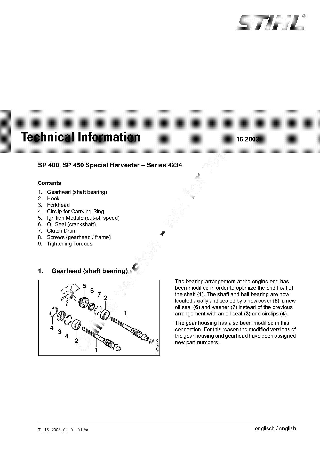
                                                             The bearing arrangement at the engine end has
                        5                                    been modified in order to optimize the end float of
                            6

                                7                            the shaft (1). The shaft and ball bearing are now
                                    2                        located axially and sealed by a new cover (5), a new
                                                             oil seal (6) and washer (7) instead of the previous
                                         1                   arrangement with an oil seal (3) and circlips (4).

                                                             The gear housing has also been modified in this
        4                                                    connection. For this reason the modified versions of
            3

                4                                            the gear housing and gearhead have been assigned
                    2
                                               412TI051 KN

                                                             new part numbers.
                                1

  TI_16_2003_01_01_01.fm                                                                       englisch / english
Page 2 of 8
Text of page 2 — search, copy, screen readers
Page 2                                                                         Technical Information 16.2003

1.1    Interchangeability                                 1.3    Service Note
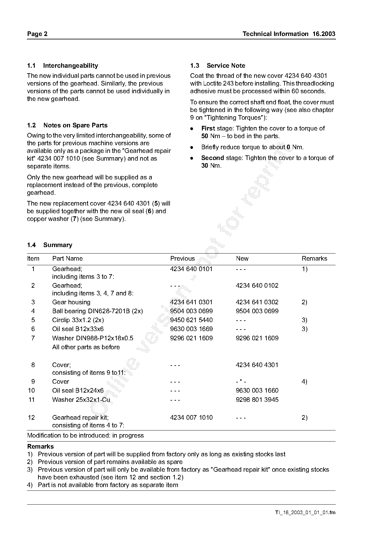
The new individual parts cannot be used in previous       Coat the thread of the new cover 4234 640 4301
versions of the gearhead. Similarly, the previous         with Loctite 243 before installing. This threadlocking
versions of the parts cannot be used individually in      adhesive must be processed within 60 seconds.
the new gearhead.
                                                          To ensure the correct shaft end float, the cover must
                                                          be tightened in the following way (see also chapter
                                                          9 on "Tightening Torques"):
1.2    Notes on Spare Parts
                                                          .     First stage: Tighten the cover to a torque of
Owing to the very limited interchangeability, some of           50 Nm – to bed in the parts.
the parts for previous machine versions are
                                                          .     Briefly reduce torque to about 0 Nm.
available only as a package in the "Gearhead repair

                                                          .     Second stage: Tighten the cover to a torque of

kit" 4234 007 1010 (see Summary) and not as
separate items.                                                 30 Nm.
Only the new gearhead will be supplied as a

replacement instead of the previous, complete
gearhead.
The new replacement cover 4234 640 4301 (5) will

be supplied together with the new oil seal (6) and
copper washer (7) (see Summary).
1.4    Summary

Item     Part Name                                  Previous                New                     Remarks

 1       Gearhead;                                  4234 640 0101           ---                     1)
         including items 3 to 7:
 2       Gearhead;                                  ---                     4234 640 0102
         including items 3, 4, 7 and 8:

 3       Gear housing                               4234 641 0301           4234 641 0302           2)

 4       Ball bearing DIN628-7201B (2x)             9504 003 0699           9504 003 0699
 5       Circlip 33x1.2 (2x)                        9450 621 5440           ---                     3)
 6       Oil seal B12x33x6                          9630 003 1669           ---                     3)

 7       Washer DIN988-P12x18x0.5                   9296 021 1609           9296 021 1609
         All other parts as before

 8       Cover;                                     ---                     4234 640 4301
         consisting of items 9 to11:

 9       Cover                                      ---                     -*-                     4)
10       Oil seal B12x24x6                          ---                     9630 003 1660

11       Washer 25x32x1-Cu                          ---                     9298 801 3945

12       Gearhead repair kit;                       4234 007 1010           ---                     2)
         consisting of items 4 to 7:
Modification to be introduced: in progress
Remarks
1) Previous version of part will be supplied from factory only as long as existing stocks last
2) Previous version of part remains available as spare
3) Previous version of part will only be available from factory as "Gearhead repair kit" once existing stocks
   have been exhausted (see item 12 and section 1.2)
4) Part is not available from factory as separate item

                                                                                           TI_16_2003_01_01_01.fm
Page 3 of 8
Text of page 3 — search, copy, screen readers
Technical Information 16.2003                                                                                            Page 3

2.    Hook                                                          2.2     Parts Availability
                                                                    Only the new hook 4234 716 1002 is available from
                                                                    the factory as replacement for previous machine
                                                                    versions. The previous rubber element remains
                             4                                      available as a spare.

                                              2
                         5
                                                                    2.3     Service Notes

                             3                1                     2.3.1 Removing the Rubber Buffer

                                                      412TI054 KN

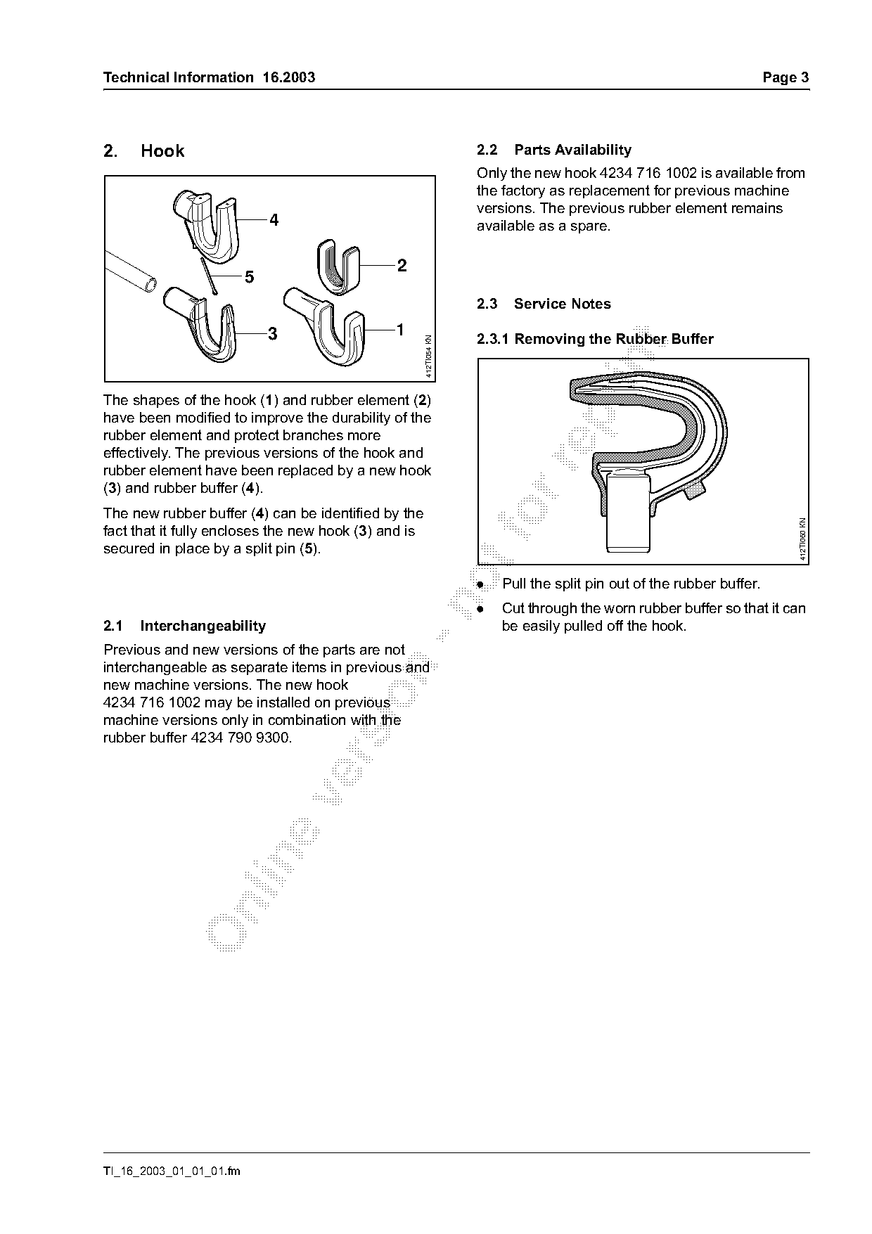
The shapes of the hook (1) and rubber element (2)

have been modified to improve the durability of the
rubber element and protect branches more
effectively. The previous versions of the hook and

rubber element have been replaced by a new hook
(3) and rubber buffer (4).
The new rubber buffer (4) can be identified by the                      fo

                                                                                                                             412TI060 KN
fact that it fully encloses the new hook (3) and is
secured in place by a split pin (5).
                                                                    .     Pull the split pin out of the rubber buffer.

                                                                    .     Cut through the worn rubber buffer so that it can
2.1   Interchangeability                                                  be easily pulled off the hook.
Previous and new versions of the parts are not
interchangeable as separate items in previous and

new machine versions. The new hook

4234 716 1002 may be installed on previous
machine versions only in combination with the
rubber buffer 4234 790 9300.

TI_16_2003_01_01_01.fm
Page 4 of 8
Text of page 4 — search, copy, screen readers
Page 4                                                                               Technical Information 16.2003

2.3.2 Installing the Rubber Buffer
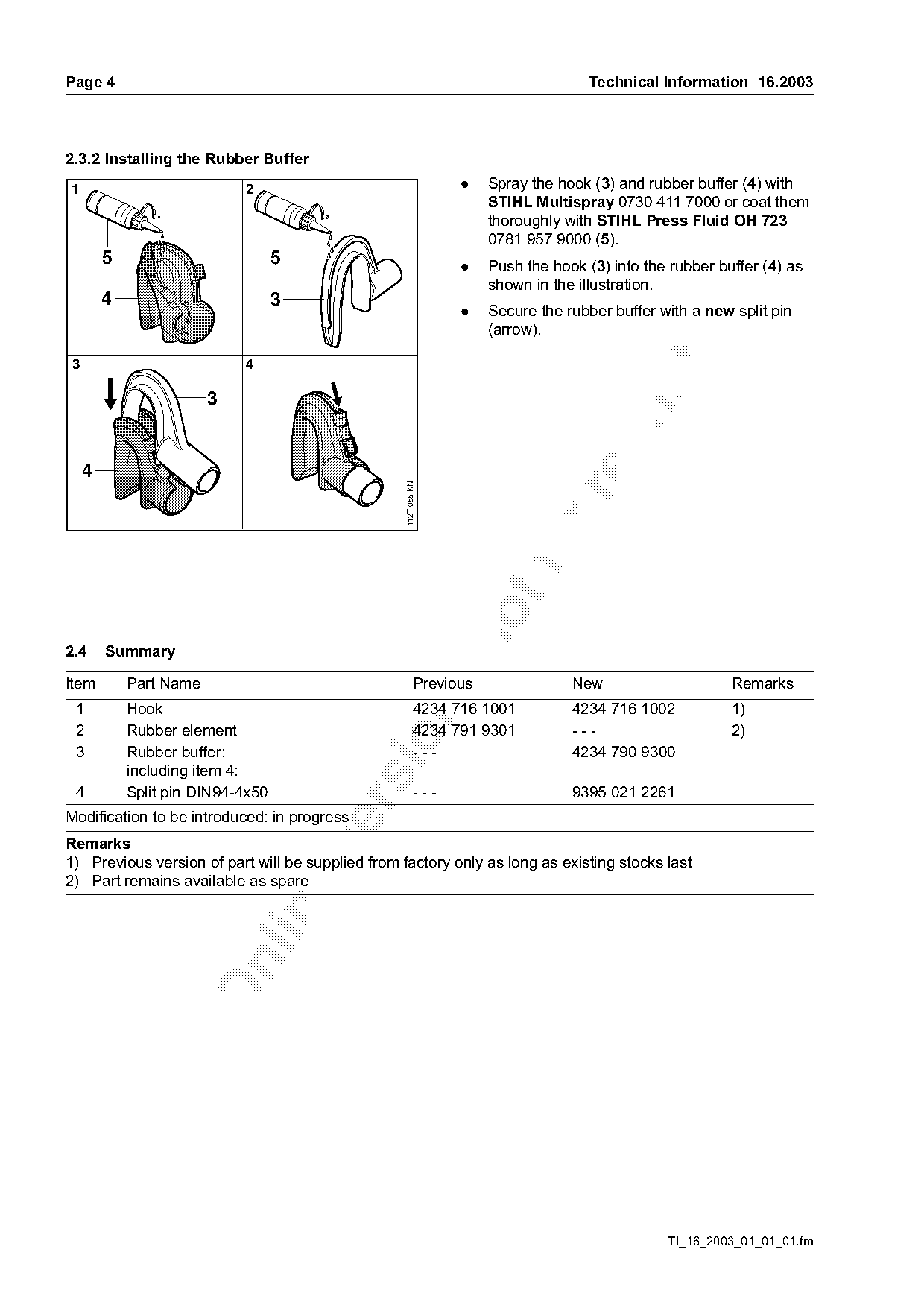
1                            2                                   .    Spray the hook (3) and rubber buffer (4) with
                                                                      STIHL Multispray 0730 411 7000 or coat them
                                                                      thoroughly with STIHL Press Fluid OH 723
                                                                      0781 957 9000 (5).
         5                          5                            .    Push the hook (3) into the rubber buffer (4) as
                                                                      shown in the illustration.
         4                          3
                                                                 .    Secure the rubber buffer with a new split pin
                                                                      (arrow).

 3                           4


     4
                                                   412TI055 KN

2.4      Summary

Item         Part Name                                     Previous               New                     Remarks
 1           Hook                                          4234 716 1001          4234 716 1002           1)

 2           Rubber element                                4234 791 9301          ---                     2)

 3           Rubber buffer;                                ---                    4234 790 9300
             including item 4:
 4           Split pin DIN94-4x50                          ---                    9395 021 2261

Modification to be introduced: in progress
Remarks

1) Previous version of part will be supplied from factory only as long as existing stocks last
2) Part remains available as spare

                                                                                                TI_16_2003_01_01_01.fm
Page 5 of 8
Text of page 5 — search, copy, screen readers
Technical Information 16.2003                                                                                      Page 5

3.    Forkhead                                                       5.    Ignition Module (cut-off speed)
                                                                     Ignition module 4234 400 1301, with a narrower cut-
                            1                                        off speed tolerance range, will be installed in the
                   4                                                 near future to further improve running behavior. The
                                                                     part number remains unchanged.
                            2
                                    3                                Engine speeds
                                                                     Ignition        Cut-off speed       Tolerance range
                                                                     module          (nominal)

                                                       412TI052 KN
                                                                     Previous        10500 rpm           + / - 800 rpm

                                                                     Modified        10500 rpm           + / - 400 rpm

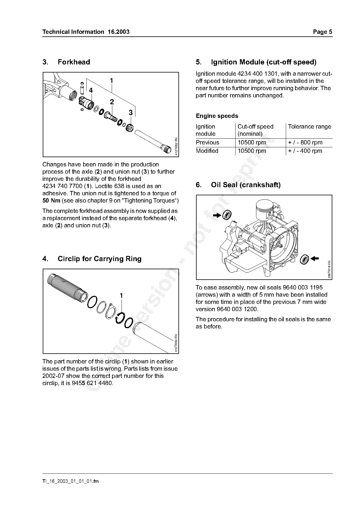
Changes have been made in the production

process of the axle (2) and union nut (3) to further
improve the durability of the forkhead
4234 740 7700 (1). Loctite 638 is used as an                         6.    Oil Seal (crankshaft)

adhesive. The union nut is tightened to a torque of
50 Nm (see also chapter 9 on "Tightening Torques“)
The complete forkhead assembly is now supplied as
a replacement instead of the separate forkhead (4),
axle (2) and union nut (3).

4.    Circlip for Carrying Ring

                                                                                                                         256TI018 KN

                                                                     To ease assembly, new oil seals 9640 003 1195
                                1                                    (arrows) with a width of 5 mm have been installed
                                                                     for some time in place of the previous 7 mm wide
                                                                     version 9640 003 1200.

                                                                     The procedure for installing the oil seals is the same
                                                                     as before.

                                                       412TI053 KN

The part number of the circlip (1) shown in earlier
issues of the parts list is wrong. Parts lists from issue

2002-07 show the correct part number for this
circlip, it is 9455 621 4480.

TI_16_2003_01_01_01.fm
Page 6 of 8
Text of page 6 — search, copy, screen readers
Page 6                                                                              Technical Information 16.2003

7.   Clutch Drum                                                The size of the screw head has been reduced from
                                                                13 mm to 12 mm without changing the part number.
                                                                This helps ensure that the weld seam near the
                                                                screw head does not prevent the screw being
                                                                turned.

                                                                Service Note
                                                                As screws with different head sizes are supplied
                                                                from the factory with the same part number, it is
                                                                possible that 12 mm and 13 mm wrenches will have

                                                  412TI056 KN

                                                                to be used to mount the gearhead.

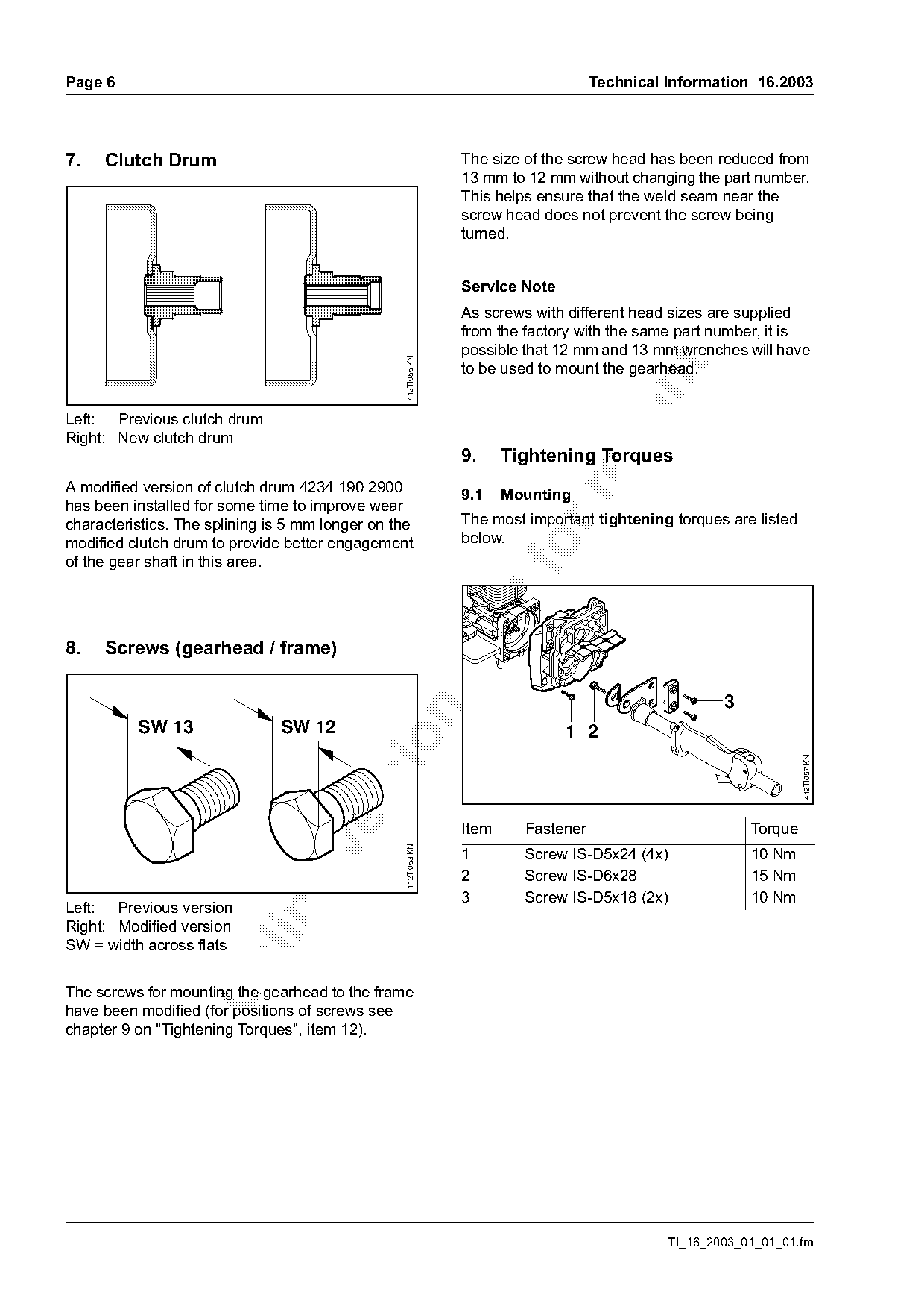
Left: Previous clutch drum
Right: New clutch drum

                                                                9.     Tightening Torques
A modified version of clutch drum 4234 190 2900                 9.1    Mounting

has been installed for some time to improve wear
characteristics. The splining is 5 mm longer on the             The most important tightening torques are listed
modified clutch drum to provide better engagement               below.
of the gear shaft in this area.

8.   Screws (gearhead / frame)


          SW 13                SW 12                                           1 2

                                                                                                                   412TI057 KN

                                                                Item     Fastener                         Torque
                                                  412TI063 KN

                                                                1        Screw IS-D5x24 (4x)              10 Nm
                                                                2        Screw IS-D6x28                   15 Nm
                                                                3        Screw IS-D5x18 (2x)              10 Nm
Left: Previous version

Right: Modified version
SW = width across flats

The screws for mounting the gearhead to the frame
have been modified (for positions of screws see
chapter 9 on "Tightening Torques", item 12).

                                                                                              TI_16_2003_01_01_01.fm
Page 7 of 8
Text of page 7 — search, copy, screen readers
Technical Information 16.2003                                                                                      Page 7

                                                                                              13
                                     7
                       6                  8
                                 5                                                                            14


                                                                                                                          412TI062 KN
                                                       412TI058 KN
                       4                         9

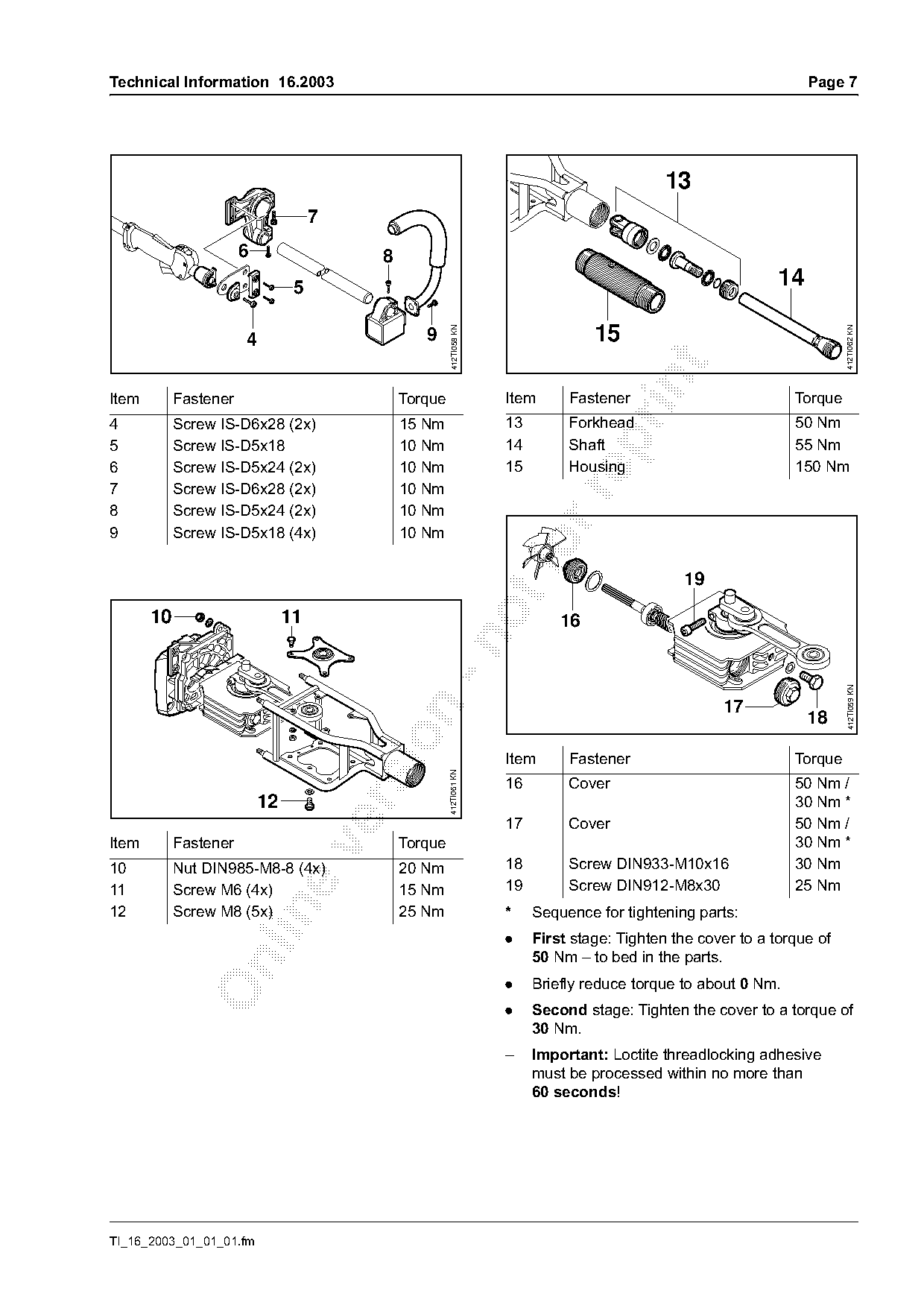
Item        Fastener                          Torque                 Item      Fastener                          Torque
4           Screw IS-D6x28 (2x)               15 Nm                  13        Forkhead                          50 Nm

5           Screw IS-D5x18                    10 Nm                  14        Shaft                             55 Nm
6           Screw IS-D5x24 (2x)               10 Nm                  15        Housing                           150 Nm
7           Screw IS-D6x28 (2x)               10 Nm

8           Screw IS-D5x24 (2x)               10 Nm
9           Screw IS-D5x18 (4x)               10 Nm
                                                                                                19
       10                       11                                            16

                                                                                                                           412TI059 KN
                                                                                                      17


                                                                     Item      Fastener                          Torque
                                                       412TI061 KN

                                                                     16        Cover                             50 Nm /
                           12                                                                                    30 Nm *

                                                                     17        Cover                             50 Nm /
Item        Fastener                          Torque                                                             30 Nm *

10          Nut DIN985-M8-8 (4x)              20 Nm                  18        Screw DIN933-M10x16               30 Nm
11          Screw M6 (4x)                     15 Nm                  19        Screw DIN912-M8x30                25 Nm

12          Screw M8 (5x)                     25 Nm                  *    Sequence for tightening parts:
                                                                     .    First stage: Tighten the cover to a torque of
                                                                          50 Nm – to bed in the parts.

                                                                     .    Briefly reduce torque to about 0 Nm.
                                                                     .    Second stage: Tighten the cover to a torque of
                                                                          30 Nm.
                                                                     –    Important: Loctite threadlocking adhesive
                                                                          must be processed within no more than
                                                                          60 seconds!

TI_16_2003_01_01_01.fm
Page 8 of 8
Text of page 8 — search, copy, screen readers
Page 8                                                                Technical Information 16.2003

9.2   Powerhead
The tightening torques for the STIHL SP 400 and SP
450 powerheads are listed in the service manual for
models FS 120, 200, 250, 300, 350, 400, 450. Use
the torques show for FS 400 and FS 450
powerheads.
Issue 01/2003 of the "Service Communications
Systems" CD-ROM includes the above-mentioned
service manual.

Last Technical Information on model SP 400: 07.2001

© ANDREAS STIHL AG & Co. KG, 2003                     Technical Documentation
                                                      D1/MTK-na                                 7874

                                                                                TI_16_2003_01_01_01.fm
Most of these PDFs embed fonts with a shifted character map, so the text above was recovered rather than copied — read it as a faithful but imperfect transcription, and treat the page image above each block as the authority where the two disagree — the figures exist only there, because they are vector drawings that text extraction cannot keep.