Technical Information · issue 17 of 2003
Carburetor; Grommet; Handle housing; Service tool
IssueTI 17/2003
Engine family 1123
Full text
Page 1 of 5
Text of page 1 — search, copy, screen readers
STIH)

Technical Information

                                                                                           17.2003

  Chainsaws STIHL MS 210, MS 230, MS 250 – Series 1123

  Contents
  1.
  2.
       Carburetor
       Grommet
  3.   Handle housing
  4.   Service tool for oil pump
  5.   Spare parts

  6.   Service notes
  7.   Summary

  1.    Carburetor

                                                                                          H
                                                                              H                   L
                                                                            3 /4    L


                                                    208TI013 KN

                                                                                                                      208TI003 KN

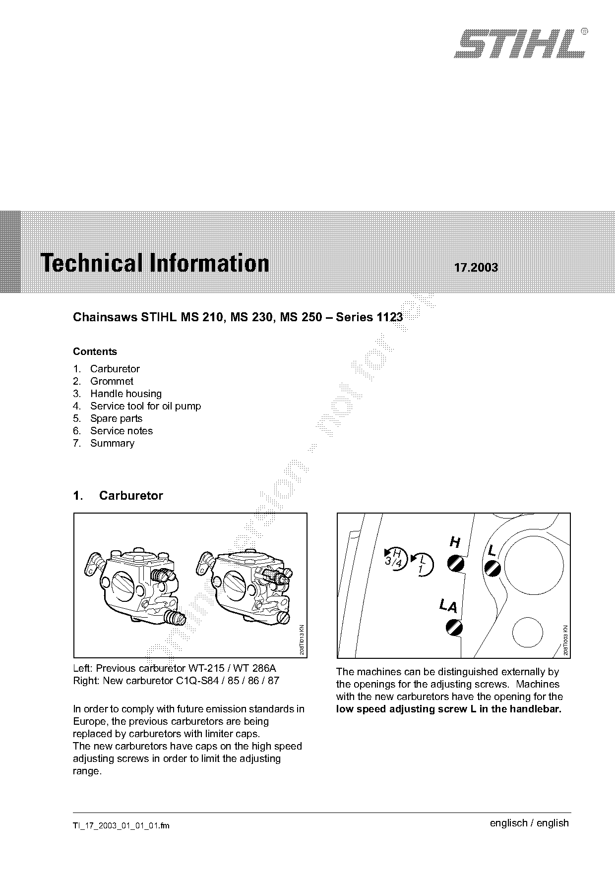
  Left: Previous carburetor WT-215 / WT 286A                      The machines can be distinguished externally by
  Right: New carburetor C1Q-S84 / 85 / 86 / 87                    the openings for the adjusting screws. Machines
                                                                  with the new carburetors have the opening for the
  In order to comply with future emission standards in            low speed adjusting screw L in the handlebar.
  Europe, the previous carburetors are being
  replaced by carburetors with limiter caps.
  The new carburetors have caps on the high speed
  adjusting screws in order to limit the adjusting
  range.

  TI_17_2003_01_01_01.fm                                                                           englisch / english
Page 2 of 5
Text of page 2 — search, copy, screen readers
Page 2                                                                                      Technical Information 17.2003

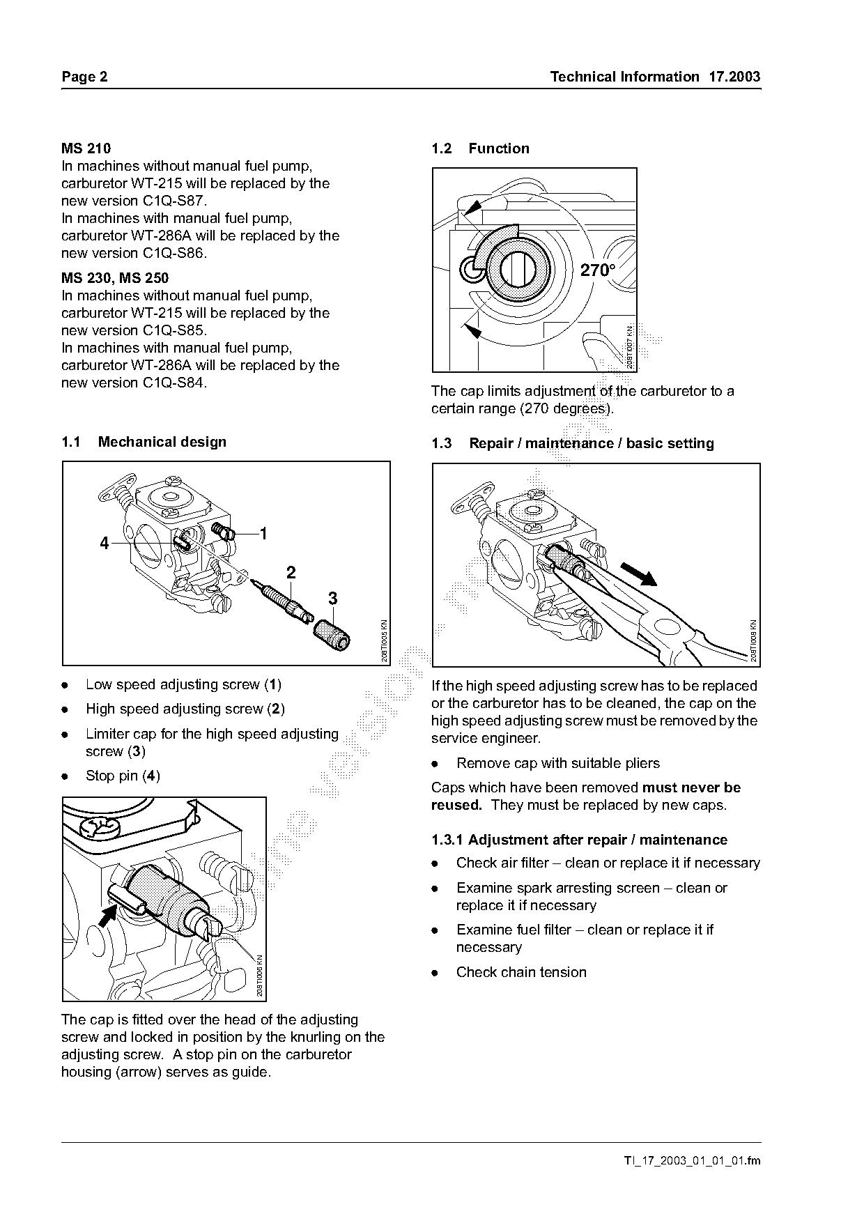
MS 210                                                                1.2     Function
In machines without manual fuel pump,
carburetor WT-215 will be replaced by the
new version C1Q-S87.
In machines with manual fuel pump,
carburetor WT-286A will be replaced by the
new version C1Q-S86.
MS 230, MS 250                                                                                   270°
In machines without manual fuel pump,
carburetor WT-215 will be replaced by the
new version C1Q-S85.

                                                                                                         208TI007 KN

In machines with manual fuel pump,

carburetor WT-286A will be replaced by the
new version C1Q-S84.
                                                                      The cap limits adjustment of the carburetor to a
                                                                      certain range (270 degrees).

1.1     Mechanical design                                             1.3     Repair / maintenance / basic setting

                                    1
        4
                                               2
                                                   3

                                                                                                                             208TI008 KN
                                                        208TI005 KN

.     Low speed adjusting screw (1)                                   If the high speed adjusting screw has to be replaced

.     High speed adjusting screw (2)                                  or the carburetor has to be cleaned, the cap on the
                                                                      high speed adjusting screw must be removed by the
.     Limiter cap for the high speed adjusting                        service engineer.
      screw (3)

                                                                      .     Remove cap with suitable pliers
.     Stop pin (4)
                                                                      Caps which have been removed must never be

                                                                      reused. They must be replaced by new caps.

                                                                      1.3.1 Adjustment after repair / maintenance

                                                                      .     Check air filter – clean or replace it if necessary
                                                                      .     Examine spark arresting screen – clean or

                                                                            replace it if necessary
                                                                      .     Examine fuel filter – clean or replace it if
                                                                            necessary
                                 208TI006 KN

                                                                      .     Check chain tension

The cap is fitted over the head of the adjusting
screw and locked in position by the knurling on the
adjusting screw. A stop pin on the carburetor
housing (arrow) serves as guide.

                                                                                                        TI_17_2003_01_01_01.fm
Page 3 of 5
Text of page 3 — search, copy, screen readers
Technical Information 17.2003                                                                            Page 3

1.3.2 Basic setting                                     Set the specified speeds within the tolerance range
                                                        of +/– 200 rpm.
                                                        1. Set speed to 3300 rpm with idle speed adjusting
                                                        screw (LA)
                 H       L
                                                        2. Turn the low speed adjusting screw (L) clockwise
                                                        or anticlockwise to obtain the highest speed
                                                        If this speed is greater than 3700 rpm:
                                                        Stop adjustment and resume with step 1.
                                                        3. Set the speed to 3300 rpm again with the idle
                                 208TI009 KN

                                                        speed adjusting screw (LA)

                                                        4. Set the speed to 2800 rpm with the low speed
                                                        adjusting screw (L)
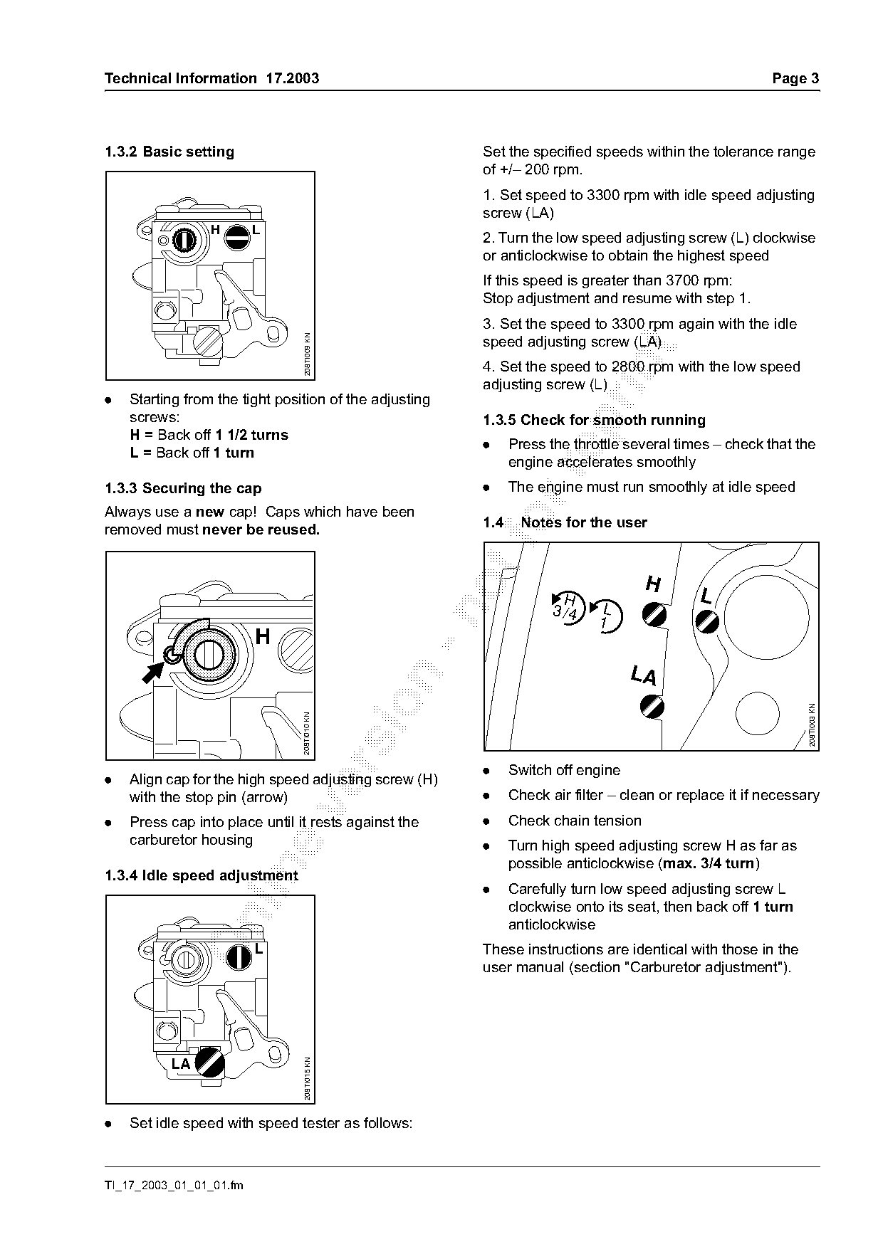
.   Starting from the tight position of the adjusting
    screws:                                             1.3.5 Check for smooth running

    H = Back off 1 1/2 turns
                                                        .     Press the throttle several times – check that the
    L = Back off 1 turn
                                                              engine accelerates smoothly

1.3.3 Securing the cap                                  .     The engine must run smoothly at idle speed
Always use a new cap! Caps which have been
removed must never be reused.
                                                        1.4 fo  Notes for the user
                                                                                    H
                                                                       H                     L
                                                                     3 /4    L

                                                                            1
                         H
                                                                                  LA

                                                                                                               208TI003 KN
                                208TI010 KN

                                                        .     Switch off engine
.   Align cap for the high speed adjusting screw (H)
    with the stop pin (arrow)                           .     Check air filter – clean or replace it if necessary

.   Press cap into place until it rests against the     .     Check chain tension
    carburetor housing                                  .     Turn high speed adjusting screw H as far as
                                                              possible anticlockwise (max. 3/4 turn)

1.3.4 Idle speed adjustment
                                                        .     Carefully turn low speed adjusting screw L
                                                              clockwise onto its seat, then back off 1 turn

                                                              anticlockwise
                         L                              These instructions are identical with those in the
                                                        user manual (section "Carburetor adjustment").
                                 208TI015 KN


.   Set idle speed with speed tester as follows:

TI_17_2003_01_01_01.fm
Page 4 of 5
Text of page 4 — search, copy, screen readers
Page 4                                                                               Technical Information 17.2003

The user can adjust the setting of the high speed                 4.   Service tool for oil pump
adjusting screw H within a range of 270 degrees.
This allows the carburetor to be set to a leaner                  A press sleeve for the MS 210, MS 230 and MS 250
setting, for instance when working in mountain                    has been added to the service tool 1123 890 2201
country.                                                          for installing and removing the oil pump. The press
                                                                  sleeve for previous machine versions is marked
1.5   Spare parts                                                 "1123" and the new press sleeve "1123/01".
The set of carburetor parts 1123 007 1060 (special                The new press sleeve positions the oil pump at a
accessory) will be available in future for the new                depth of 6 mm instead of 4.5 mm as in the past.
carburetors with limiter caps.

2.    Grommet                                                             A                         A

                                                                                                                       135TI040 KN
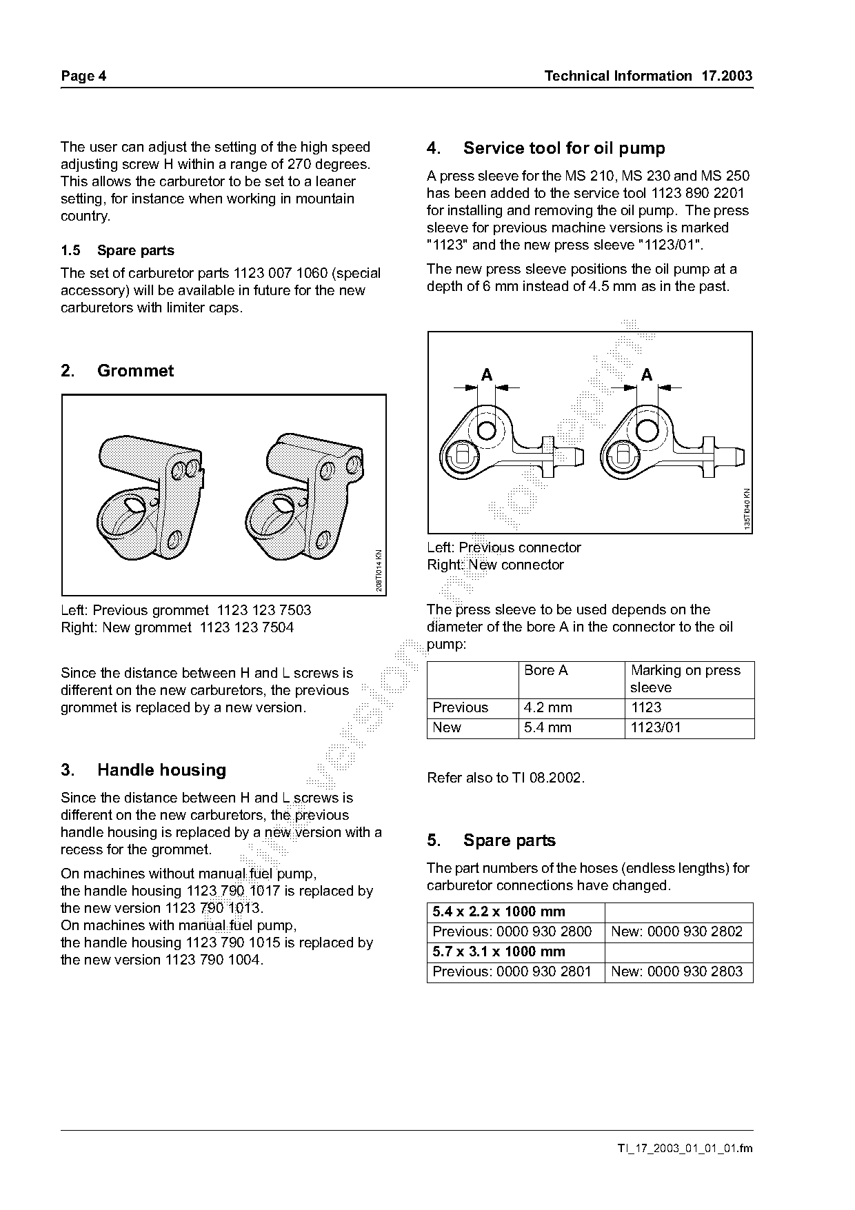
                                                                  Left: Previous connector
                                                    208TI014 KN

                                                                  Right: New connector

Left: Previous grommet 1123 123 7503                              The press sleeve to be used depends on the
Right: New grommet 1123 123 7504                                  diameter of the bore A in the connector to the oil
                                                                  pump:

Since the distance between H and L screws is                                     Bore A            Marking on press

different on the new carburetors, the previous                                                     sleeve
grommet is replaced by a new version.                             Previous       4.2 mm            1123
                                                                  New            5.4 mm            1123/01

3.    Handle housing                                              Refer also to TI 08.2002.

Since the distance between H and L screws is
different on the new carburetors, the previous
handle housing is replaced by a new version with a
                                                                  5.   Spare parts

recess for the grommet.
On machines without manual fuel pump,                             The part numbers of the hoses (endless lengths) for
the handle housing 1123 790 1017 is replaced by                   carburetor connections have changed.

the new version 1123 790 1013.                                    5.4 x 2.2 x 1000 mm
On machines with manual fuel pump,                                Previous: 0000 930 2800      New: 0000 930 2802
the handle housing 1123 790 1015 is replaced by
                                                                  5.7 x 3.1 x 1000 mm
the new version 1123 790 1004.
                                                                  Previous: 0000 930 2801      New: 0000 930 2803

                                                                                                 TI_17_2003_01_01_01.fm
Page 5 of 5
Text of page 5 — search, copy, screen readers
Technical Information 17.2003                                                                      Page 5

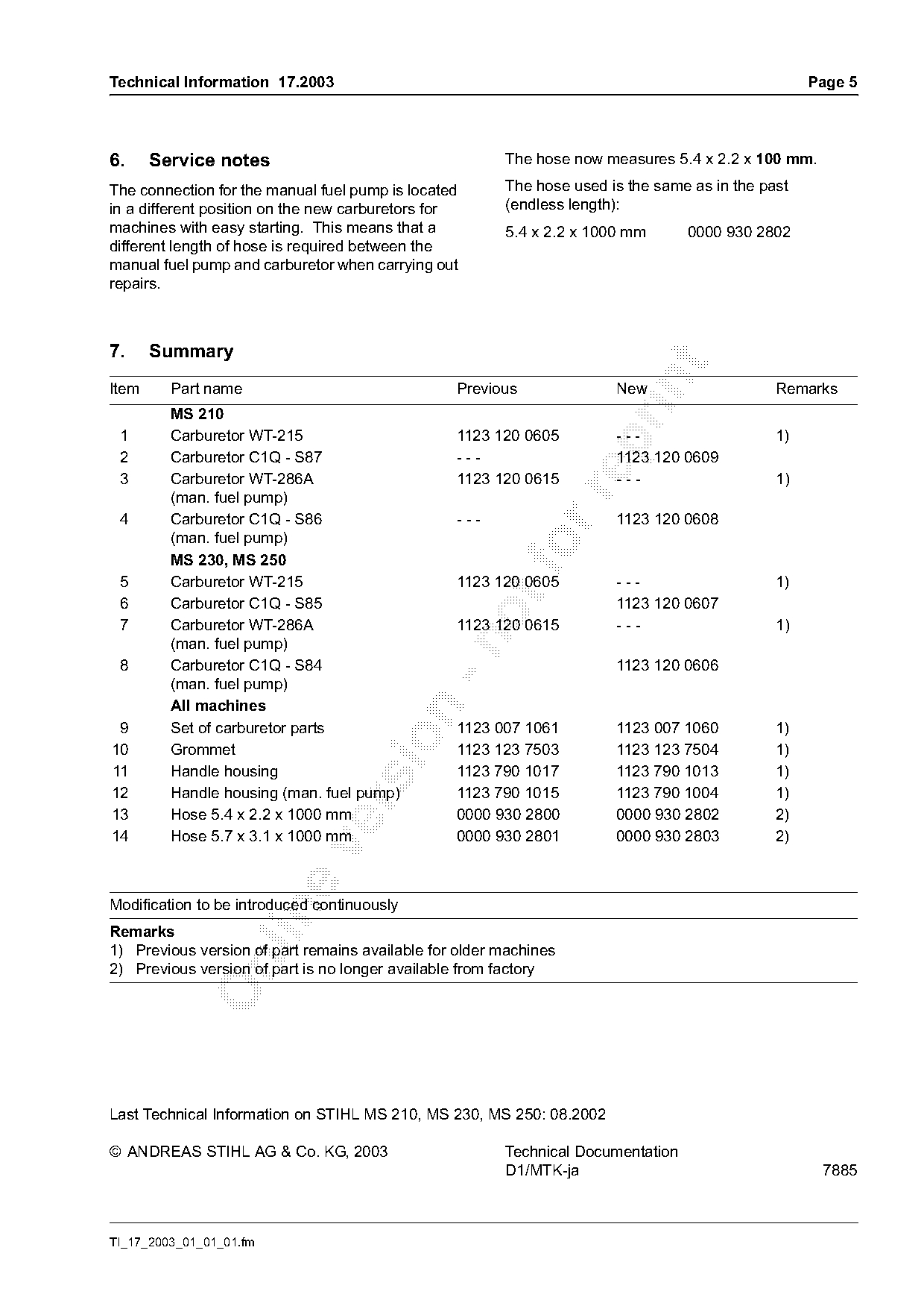
6.     Service notes                                    The hose now measures 5.4 x 2.2 x 100 mm.

The connection for the manual fuel pump is located      The hose used is the same as in the past
in a different position on the new carburetors for      (endless length):
machines with easy starting. This means that a          5.4 x 2.2 x 1000 mm       0000 930 2802
different length of hose is required between the
manual fuel pump and carburetor when carrying out
repairs.

7.     Summary

Item     Part name                               Previous              New                    Remarks
         MS 210
 1       Carburetor WT-215                       1123 120 0605         ---                    1)

 2       Carburetor C1Q - S87                    ---                   1123 120 0609
 3       Carburetor WT-286A                      1123 120 0615         ---                    1)

         (man. fuel pump)
 4       Carburetor C1Q - S86                    ---                   1123 120 0608
         (man. fuel pump)
         MS 230, MS 250
 5       Carburetor WT-215                       1123 120 0605         ---                    1)
 6       Carburetor C1Q - S85                                          1123 120 0607
 7       Carburetor WT-286A                      1123 120 0615         ---                    1)

         (man. fuel pump)
 8       Carburetor C1Q - S84                                          1123 120 0606
         (man. fuel pump)
         All machines

 9       Set of carburetor parts                 1123 007 1061         1123 007 1060          1)

10       Grommet                                 1123 123 7503         1123 123 7504          1)
11       Handle housing                          1123 790 1017         1123 790 1013          1)
12       Handle housing (man. fuel pump)         1123 790 1015         1123 790 1004          1)

13       Hose 5.4 x 2.2 x 1000 mm                0000 930 2800         0000 930 2802          2)
14       Hose 5.7 x 3.1 x 1000 mm                0000 930 2801         0000 930 2803          2)

Modification to be introduced continuously

Remarks
1) Previous version of part remains available for older machines

2) Previous version of part is no longer available from factory

Last Technical Information on STIHL MS 210, MS 230, MS 250: 08.2002

© ANDREAS STIHL AG & Co. KG, 2003                       Technical Documentation
                                                        D1/MTK-ja                                   7885

TI_17_2003_01_01_01.fm
Most of these PDFs embed fonts with a shifted character map, so the text above was recovered rather than copied — read it as a faithful but imperfect transcription, and treat the page image above each block as the authority where the two disagree — the figures exist only there, because they are vector drawings that text extraction cannot keep.