Technical Information · issue 32 of 2003
Technical description; Specifications; Service accessories and special tools; Service note; Spare parts
IssueTI 32/2003
Engine family 1135
Full text
Page 1 of 14
Text of page 1 — search, copy, screen readers
STIH)

Technical Information

                                                              32.2003

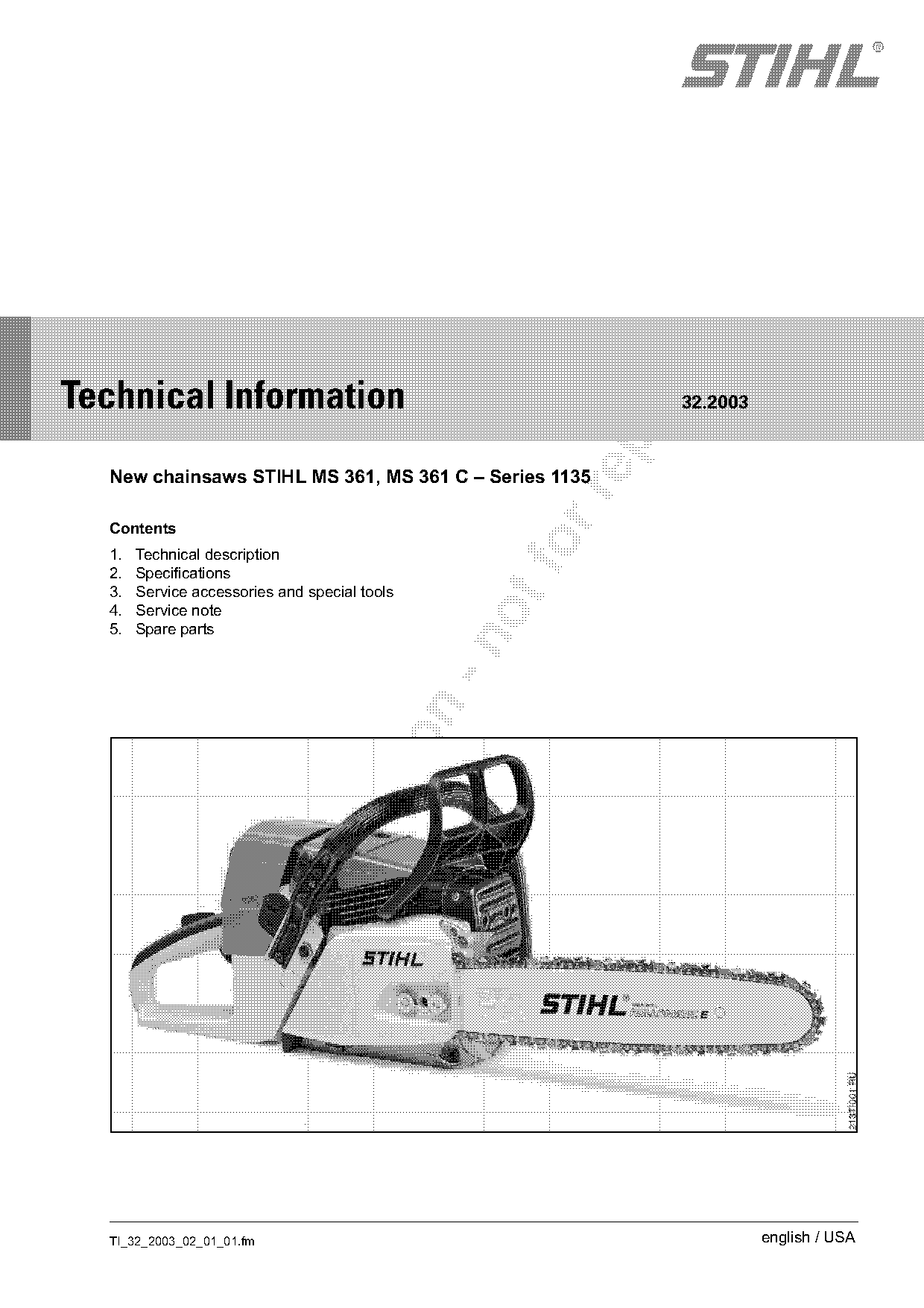
  New chainsaws STIHL MS 361, MS 361 C – Series 1135

  Contents
  1.
  2.
       Technical description
       Specifications
  3.   Service accessories and special tools
  4.   Service note
  5.   Spare parts

  TI_32_2003_02_01_01.fm                                                english / USA
Page 2 of 14
Text of page 2 — search, copy, screen readers
Page 2                                                                         Technical Information 32.2003

The new STIHL MS 361 and MS 361 C chainsaws              Crankshaft
cover everything from thinning through harvesting
                                                         .   Durable, two-part crankshaft
small timber and cutting firewood. These highly
versatile chainsaws display considerable engine          .   Small-end bearing and crankpin bearing with
power and high torque over a large range of speeds,          approx. 40 % greater load capacity than in the
with a very favorable power-to-weight ratio.                 model MS 360
The new models feature a revised anti-vibration          .   Crankpin bearing with special heat treatment
system with rubber buffer, two springs and a             Diaphragm carburetor with full-throttle partially
microcellular polyurethane element. The ignition         fixed nozzle, part-throttle nozzle and dependent
system with electronic ignition timing not only allows   idling circuit
the machine to be started snoothly, but also ensures
                                                         Limiter caps limit the adjustment range for the high

optimum performance.

                                                         speed adjusting screw and low speed adjusting
The MS 361 is equipped with the ElastoStart starter      screw (approx. 3/4 turn)
handle and decompression valve for convenient            (see section 4.1).
starting. The MS 361 C additionally includes the

QS chain brake system.                                   Accelerator pump

1.     Technical description

1.1    Power unit
STIHL single-cylinder two-stroke engine
Cylinder
.     Four-port system for better mixture preparation,
                                                                                        a
      optimum combustion and lower exhaust

                                                                                                              213TI014 KN
      emissions                                                                  4          3
                                                                           2
.     Large cooling-air area                                          51
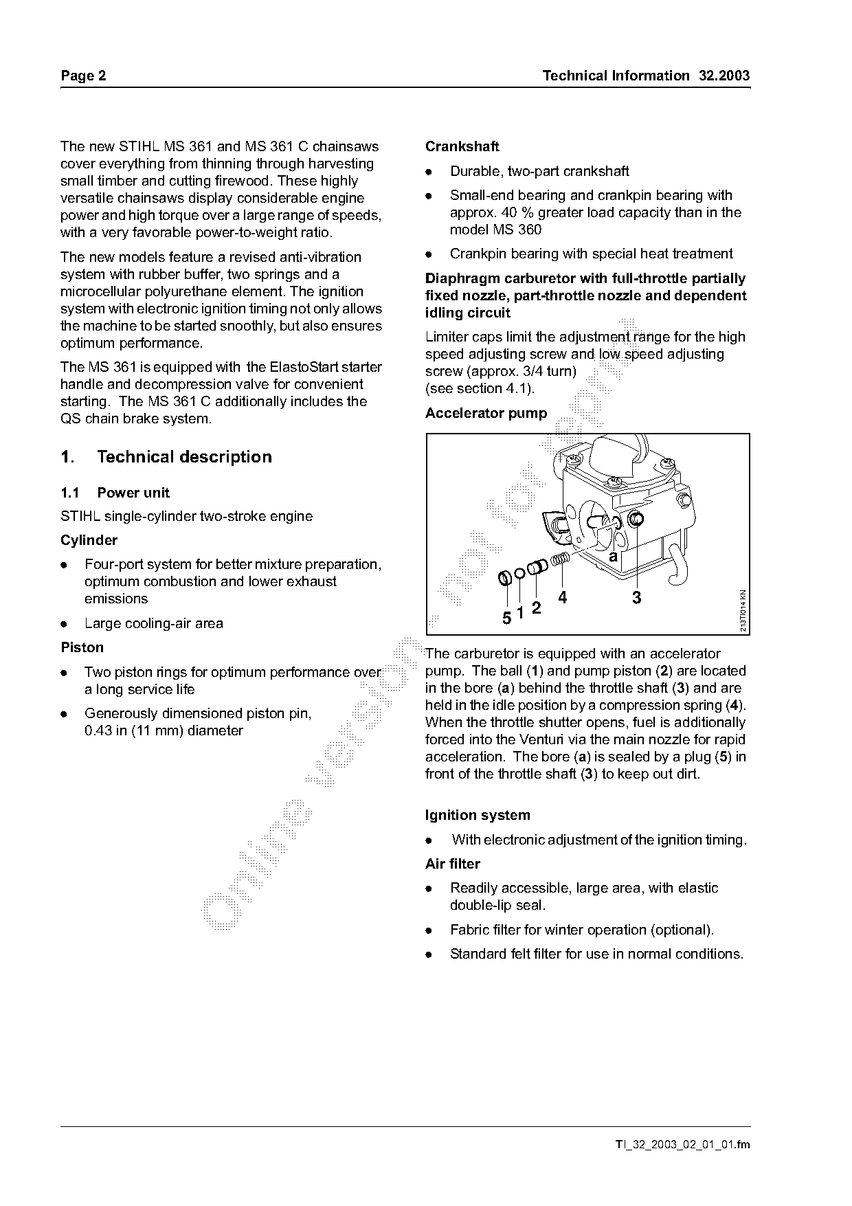
Piston                                                   The carburetor is equipped with an accelerator

.     Two piston rings for optimum performance over      pump. The ball (1) and pump piston (2) are located

      a long service life                                in the bore (a) behind the throttle shaft (3) and are
                                                         held in the idle position by a compression spring (4).
.     Generously dimensioned piston pin,
                                                         When the throttle shutter opens, fuel is additionally
      0.43 in (11 mm) diameter
                                                         forced into the Venturi via the main nozzle for rapid

                                                         acceleration. The bore (a) is sealed by a plug (5) in
                                                         front of the throttle shaft (3) to keep out dirt.

                                                         Ignition system
                                                         .   With electronic adjustment of the ignition timing.

                                                         Air filter
                                                         .   Readily accessible, large area, with elastic

                                                             double-lip seal.
                                                         .   Fabric filter for winter operation (optional).
                                                         .   Standard felt filter for use in normal conditions.

                                                                                         TI_32_2003_02_01_01.fm
Page 3 of 14
Text of page 3 — search, copy, screen readers
Technical Information 32.2003                                                                                       Page 3

Muffler                                                             1.4    Winter operation
.     Single-chamber muffler with spark arresting
      screen.
Clutch                                                                                                          1
.     With three steel clutch shoes.

1.2    Anti-vibration system


                                                                                                                            213TI003 KN
                                                      213TI002 KN

                                4
                                       1

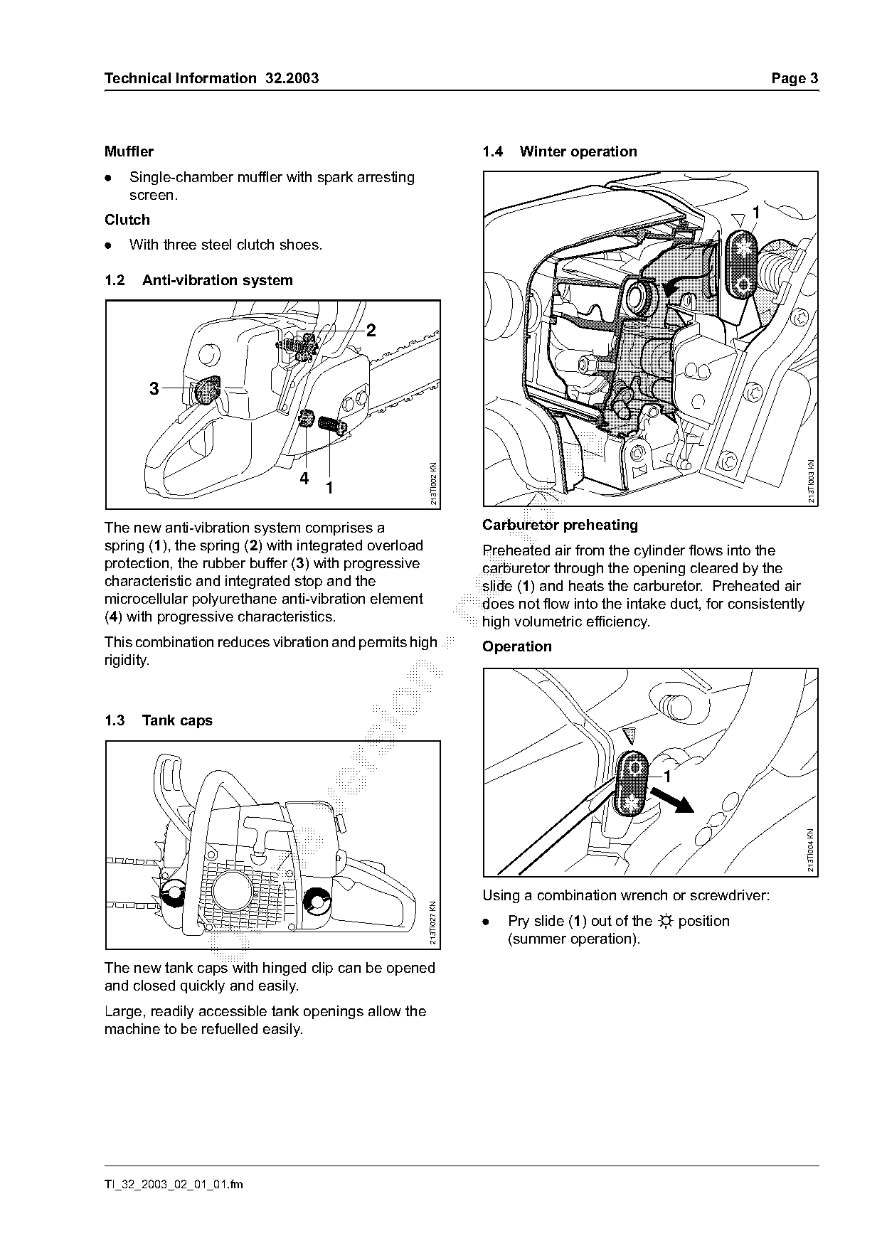
The new anti-vibration system comprises a
spring (1), the spring (2) with integrated overload
                                                                    Carburetor preheating
                                                                    Preheated air from the cylinder flows into the
protection, the rubber buffer (3) with progressive                  carburetor through the opening cleared by the
characteristic and integrated stop and the                          slide (1) and heats the carburetor. Preheated air
microcellular polyurethane anti-vibration element                   does not flow into the intake duct, for consistently

(4) with progressive characteristics.                               high volumetric efficiency.
This combination reduces vibration and permits high                 Operation
rigidity.

1.3    Tank caps


                                                                                                                           213TI004 KN

                                                                    Using a combination wrench or screwdriver:
                                                      213TI027 KN

                                                                    .

                                                                          Pry slide (1) out of the s position
                                                                          (summer operation).

The new tank caps with hinged clip can be opened
and closed quickly and easily.
Large, readily accessible tank openings allow the
machine to be refuelled easily.

TI_32_2003_02_01_01.fm
Page 4 of 14
Text of page 4 — search, copy, screen readers
Page 4                                                                                Technical Information 32.2003

                                                    213TI005 KN

                                                                                                                       214TI001 KN
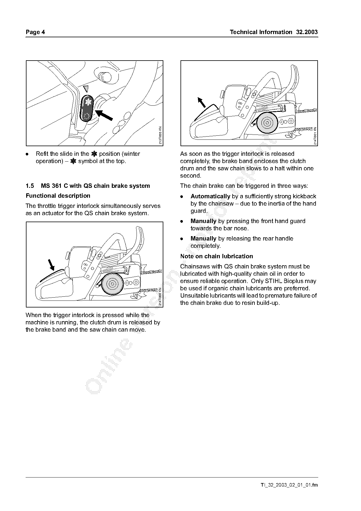
.     Refit the slide in the r position (winter                   As soon as the trigger interlock is released
      operation) – r symbol at the top.                           completely, the brake band encloses the clutch
                                                                  drum and the saw chain slows to a halt within one

                                                                  second.
1.5     MS 361 C with QS chain brake system                       The chain brake can be triggered in three ways:

Functional description                                            .   Automatically by a sufficiently strong kickback
The throttle trigger interlock simultaneously serves                  by the chainsaw – due to the inertia of the hand
                                                                      guard.
as an actuator for the QS chain brake system.
                                                                  .
                                                                      Manually by pressing the front hand guard
                                                                      towards the bar nose.
                                                                  .   Manually by releasing the rear handle
                                                                      completely.

                                                                  Note on chain lubrication
                                                                  Chainsaws with QS chain brake system must be
                                                                  lubricated with high-quality chain oil in order to

                                                                  ensure reliable operation. Only STIHL Bioplus may
                                                                  be used if organic chain lubricants are preferred.
                                                   214TI000 KN

                                                                  Unsuitable lubricants will lead to premature failure of
                                                                  the chain brake due to resin build-up.

When the trigger interlock is pressed while the
machine is running, the clutch drum is released by
the brake band and the saw chain can move.

                                                                                                  TI_32_2003_02_01_01.fm
Page 5 of 14
Text of page 5 — search, copy, screen readers
Technical Information 32.2003                                                                      Page 5

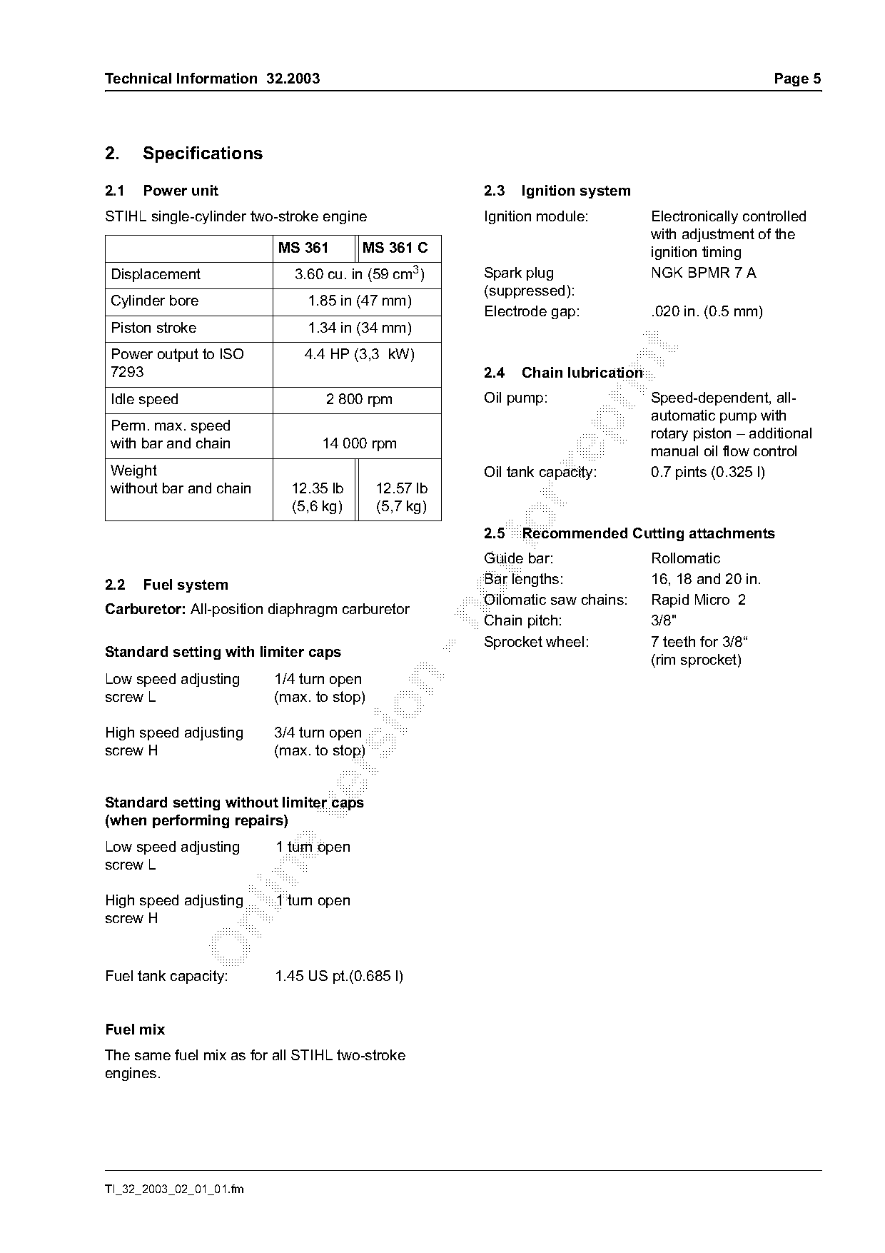
2.    Specifications

2.1   Power unit                                     2.3   Ignition system
STIHL single-cylinder two-stroke engine              Ignition module:          Electronically controlled
                                                                               with adjustment of the
                         MS 361        MS 361 C                                ignition timing
Displacement                3.60 cu. in (59 cm3)     Spark plug                NGK BPMR 7 A
                                                     (suppressed):
Cylinder bore                 1.85 in (47 mm)
                                                     Electrode gap:            .020 in. (0.5 mm)
Piston stroke                 1.34 in (34 mm)

Power output to ISO          4.4 HP (3,3 kW)

7293                                                 2.4   Chain lubrication
Idle speed                       2 800 rpm           Oil pump:                 Speed-dependent, all-
                                                                               automatic pump with

Perm. max. speed
                                                                               rotary piston – additional
with bar and chain              14 000 rpm
                                                                               manual oil flow control
Weight                                               Oil tank capacity:        0.7 pints (0.325 l)

without bar and chain      12.35 lb       12.57 lb
                           (5,6 kg)       (5,7 kg)
                                                     2.5   Recommended Cutting attachments
                                                     Guide bar:                Rollomatic
2.2   Fuel system                                    Bar lengths:              16, 18 and 20 in.
                                                     Oilomatic saw chains:     Rapid Micro 2
Carburetor: All-position diaphragm carburetor

                                                     Chain pitch:              3/8"
                                                     Sprocket wheel:           7 teeth for 3/8“
Standard setting with limiter caps
                                                                               (rim sprocket)
Low speed adjusting      1/4 turn open

screw L                  (max. to stop)

High speed adjusting     3/4 turn open
screw H                  (max. to stop)

Standard setting without limiter caps

(when performing repairs)
Low speed adjusting      1 turn open
screw L

High speed adjusting     1 turn open
screw H

Fuel tank capacity:      1.45 US pt.(0.685 l)

Fuel mix
The same fuel mix as for all STIHL two-stroke
engines.

TI_32_2003_02_01_01.fm
Page 6 of 14
Text of page 6 — search, copy, screen readers
Page 6                                                                            Technical Information 32.2003

3.    Service accessories and special
      tools

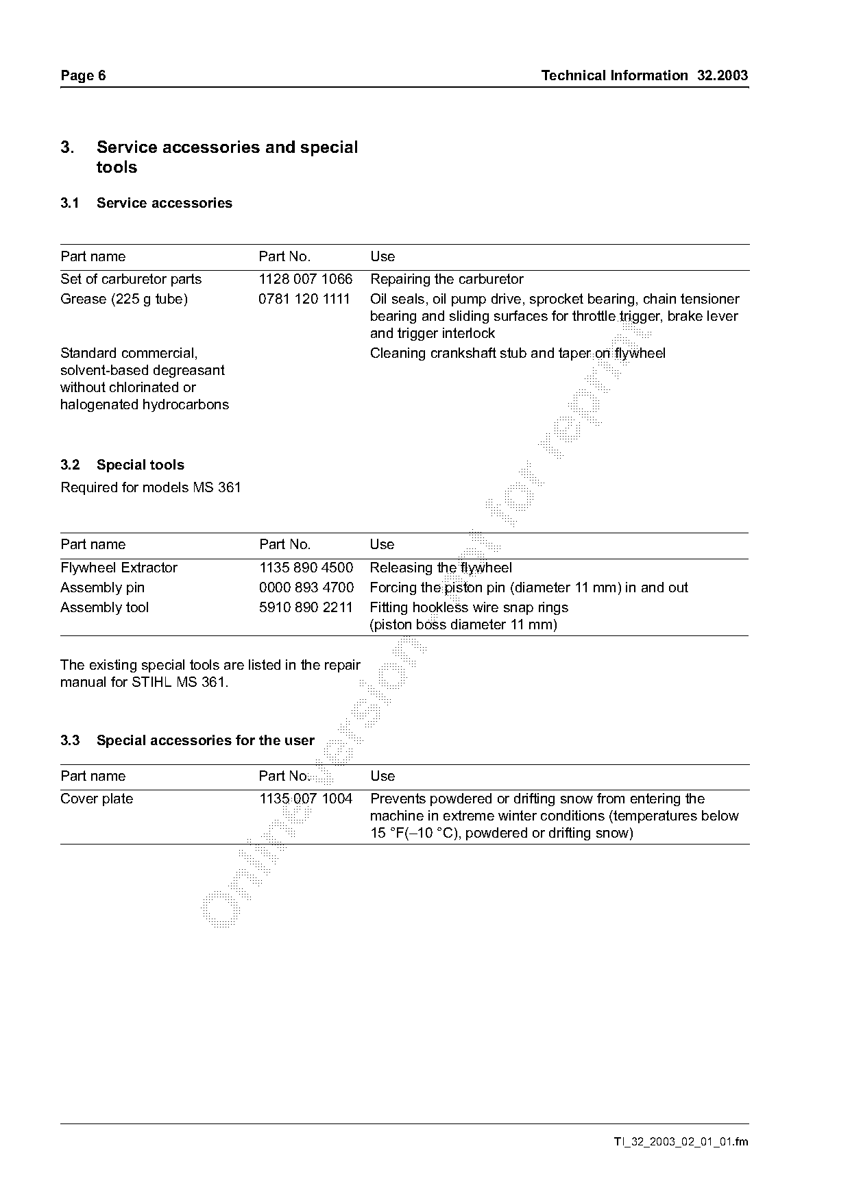
3.1   Service accessories

Part name                        Part No.             Use
Set of carburetor parts          1128 007 1066        Repairing the carburetor
Grease (225 g tube)              0781 120 1111        Oil seals, oil pump drive, sprocket bearing, chain tensioner
                                                      bearing and sliding surfaces for throttle trigger, brake lever
                                                      and trigger interlock

Standard commercial,                                  Cleaning crankshaft stub and taper on flywheel
solvent-based degreasant
without chlorinated or
halogenated hydrocarbons

3.2   Special tools
Required for models MS 361
Part name                        Part No.             Use
Flywheel Extractor               1135 890 4500        Releasing the flywheel
Assembly pin                     0000 893 4700        Forcing the piston pin (diameter 11 mm) in and out

Assembly tool                    5910 890 2211        Fitting hookless wire snap rings
                                                      (piston boss diameter 11 mm)

The existing special tools are listed in the repair

manual for STIHL MS 361.

3.3   Special accessories for the user

Part name                        Part No.             Use

Cover plate                      1135 007 1004        Prevents powdered or drifting snow from entering the
                                                      machine in extreme winter conditions (temperatures below
                                                      15 °F(–10 °C), powdered or drifting snow)

                                                                                               TI_32_2003_02_01_01.fm
Page 7 of 14
Text of page 7 — search, copy, screen readers
Technical Information 32.2003                                                                                        Page 7

4.     Service note                                                  4.1.2 Maintenance / repair

The specific national safety regulations and the
safety instructions in the user's manual must be
observed when starting and operating the chainsaw.

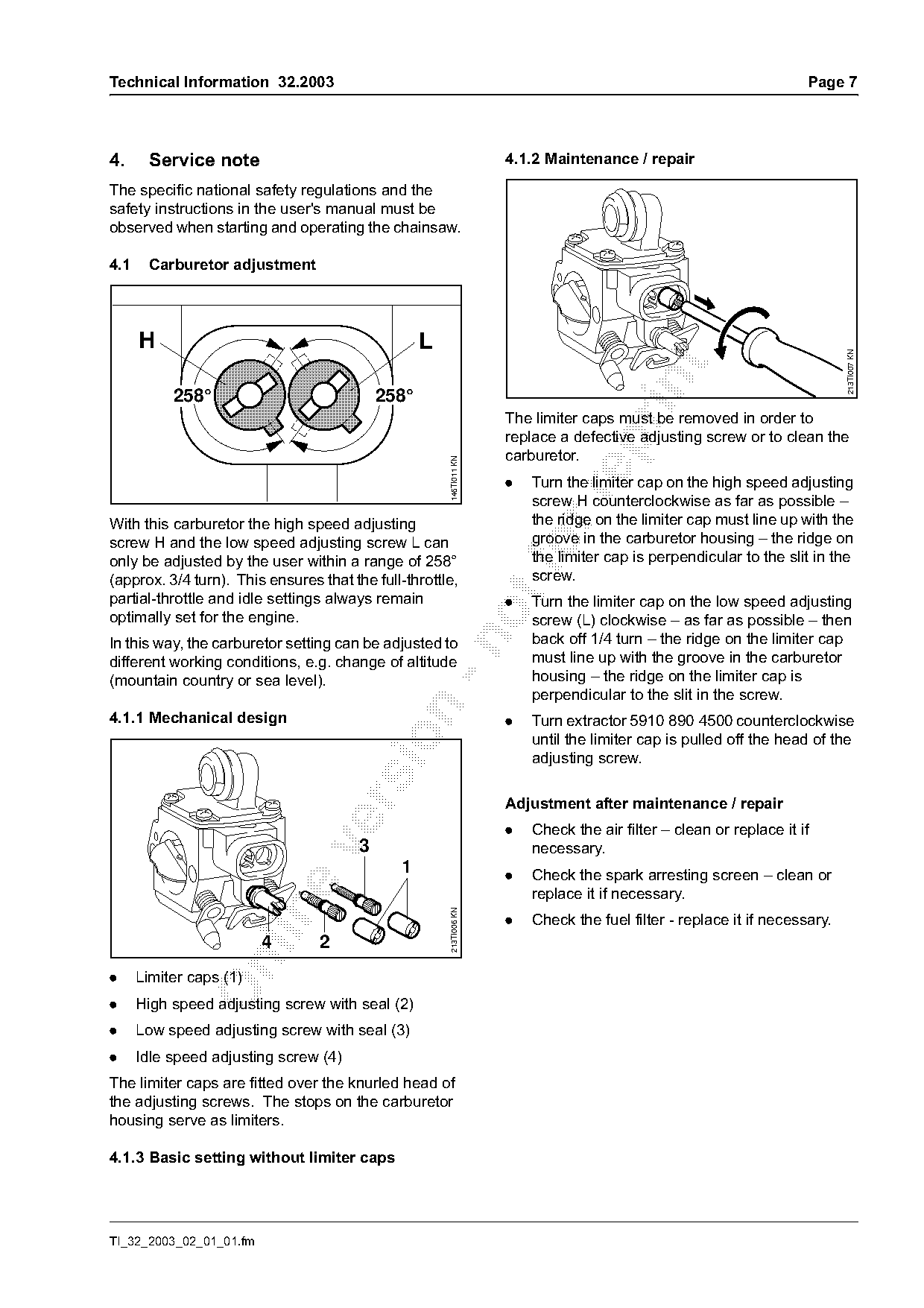
4.1    Carburetor adjustment

      H                                            L

                                                                                                                            213TI007 KN
           258°                             258°
                                                                     The limiter caps must be removed in order to
                                                                     replace a defective adjusting screw or to clean the

                                                       146TI011 KN
                                                                     carburetor.
                                                                     .   Turn the limiter cap on the high speed adjusting

                                                                         screw H counterclockwise as far as possible –
With this carburetor the high speed adjusting                            the ridge on the limiter cap must line up with the
screw H and the low speed adjusting screw L can                          groove in the carburetor housing – the ridge on
only be adjusted by the user within a range of 258°
                                                                         the limiter cap is perpendicular to the slit in the
                                                                         screw.
(approx. 3/4 turn). This ensures that the full-throttle,
partial-throttle and idle settings always remain
                                                                     .   Turn the limiter cap on the low speed adjusting
optimally set for the engine.                                            screw (L) clockwise – as far as possible – then
                                                                         back off 1/4 turn – the ridge on the limiter cap

In this way, the carburetor setting can be adjusted to
different working conditions, e.g. change of altitude                    must line up with the groove in the carburetor
(mountain country or sea level).                                         housing – the ridge on the limiter cap is
                                                                         perpendicular to the slit in the screw.

4.1.1 Mechanical design                                              .   Turn extractor 5910 890 4500 counterclockwise

                                                                         until the limiter cap is pulled off the head of the
                                                                         adjusting screw.

                                                                     Adjustment after maintenance / repair

                                                                     .   Check the air filter – clean or replace it if
                                        3

                                                                         necessary.
                                              1                      .   Check the spark arresting screen – clean or
                                                                         replace it if necessary.

                                                       213TI006 KN

                                                                     .   Check the fuel filter - replace it if necessary.
                         4       2

.     Limiter caps (1)
.     High speed adjusting screw with seal (2)
.     Low speed adjusting screw with seal (3)
.     Idle speed adjusting screw (4)
The limiter caps are fitted over the knurled head of
the adjusting screws. The stops on the carburetor
housing serve as limiters.

4.1.3 Basic setting without limiter caps

TI_32_2003_02_01_01.fm
Page 8 of 14
Text of page 8 — search, copy, screen readers
Page 8                                                                                    Technical Information 32.2003

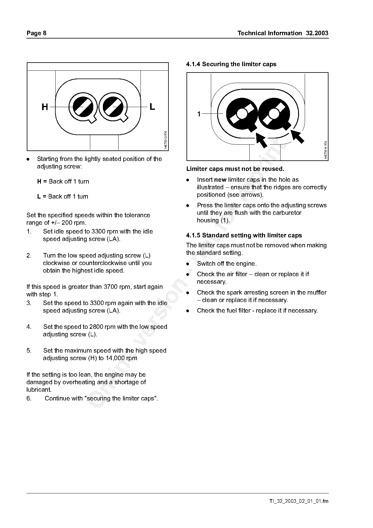
                                                                      4.1.4 Securing the limiter caps

      H                                         L
                                                                          1

                                                        146TI013 KN

                                                                                                                             146TI014 KN
.    Starting from the lightly seated position of the
     adjusting screw:                                                 Limiter caps must not be reused.

     H = Back off 1 turn                                              .   Insert new limiter caps in the hole as
                                                                          illustrated – ensure that the ridges are correctly
     L = Back off 1 turn                                                  positioned (see arrows).

                                                                      .   Press the limiter caps onto the adjusting screws
Set the specified speeds within the tolerance                             until they are flush with the carburetor
range of +/– 200 rpm.
1.    Set idle speed to 3300 rpm with the idle
                                                                          housing (1).

                                                                      4.1.5 Standard setting with limiter caps
      speed adjusting screw (LA).
                                                                      The limiter caps must not be removed when making
2.     Turn the low speed adjusting screw (L)                         the standard setting.

       clockwise or counterclockwise until you                        .   Switch off the engine.
       obtain the highest idle speed.
                                                                      .   Check the air filter – clean or replace it if
                                                                          necessary.
If this speed is greater than 3700 rpm, start again

with step 1.                                                          .   Check the spark arresting screen in the muffler

                                                                          – clean or replace it if necessary.
3.      Set the speed to 3300 rpm again with the idle
        speed adjusting screw (LA).                                   .   Check the fuel filter - replace it if necessary.

4.     Set the speed to 2800 rpm with the low speed
       adjusting screw (L).

5.     Set the maximum speed with the high speed
       adjusting screw (H) to 14,000 rpm

If the setting is too lean, the engine may be
damaged by overheating and a shortage of

lubricant.
6.      Continue with "securing the limiter caps".

                                                                                                       TI_32_2003_02_01_01.fm
Page 9 of 14
Text of page 9 — search, copy, screen readers
Technical Information 32.2003                                                                                       Page 9

                                                                   Adjustment for use in mountain country
                                                                   A marginal adjustment may be necessary if the
                                                                   engine does not run satisfactorily:
                                                                   .     Check the standard setting.
                                                                   .     Let the engine warm up.
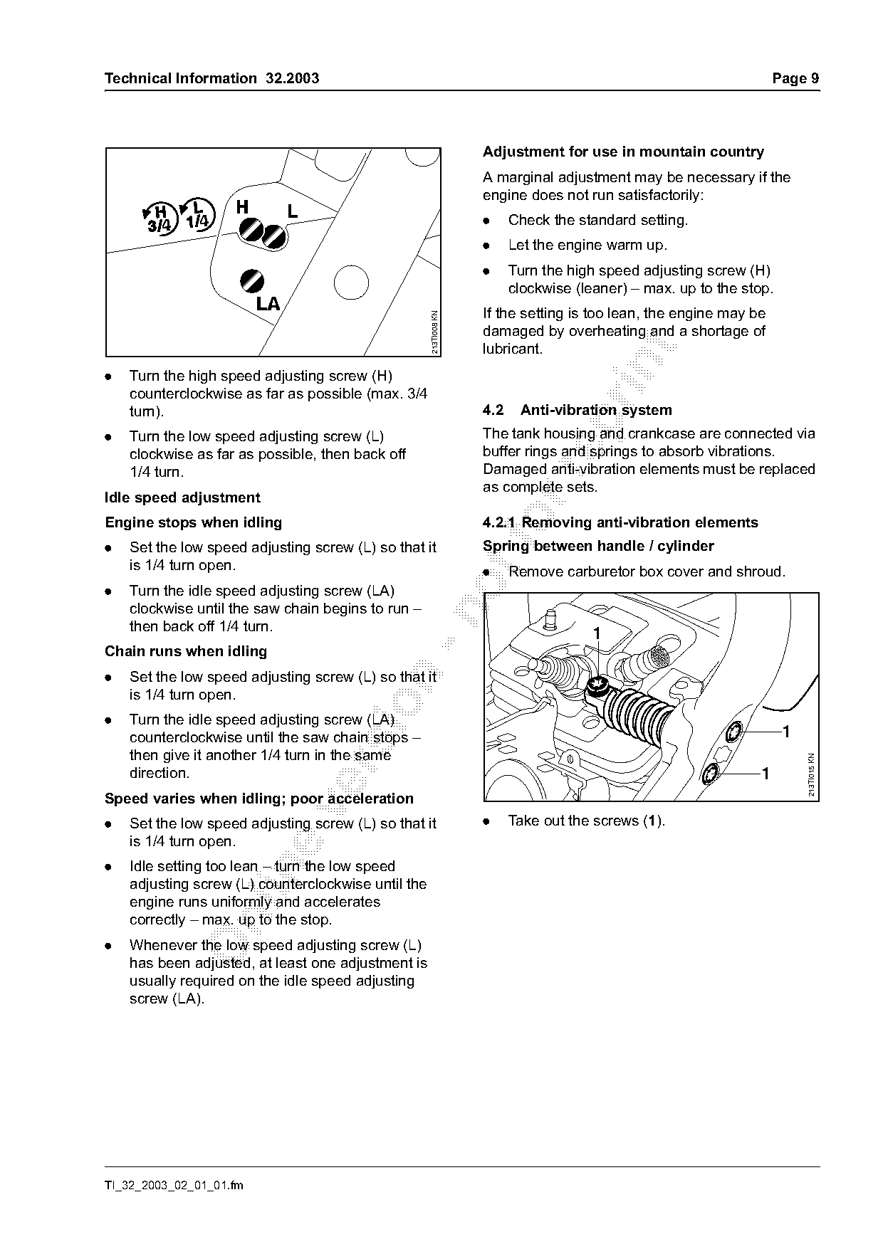
                                                                   .     Turn the high speed adjusting screw (H)
                                                                         clockwise (leaner) – max. up to the stop.
                                                                   If the setting is too lean, the engine may be

                                                     213TI008 KN
                                                                   damaged by overheating and a shortage of
                                                                   lubricant.

.   Turn the high speed adjusting screw (H)
    counterclockwise as far as possible (max. 3/4
    turn).                                                         4.2    Anti-vibration system

.   Turn the low speed adjusting screw (L)                         The tank housing and crankcase are connected via
    clockwise as far as possible, then back off                    buffer rings and springs to absorb vibrations.
    1/4 turn.                                                      Damaged anti-vibration elements must be replaced

                                                                   as complete sets.
Idle speed adjustment
Engine stops when idling
.   Set the low speed adjusting screw (L) so that it
                                                                   4.2.1 Removing anti-vibration elements
                                                                   Spring between handle / cylinder
    is 1/4 turn open.                                              .     Remove carburetor box cover and shroud.
.   Turn the idle speed adjusting screw (LA)
    clockwise until the saw chain begins to run –

    then back off 1/4 turn.
                                                                                      1
Chain runs when idling
.   Set the low speed adjusting screw (L) so that it

    is 1/4 turn open.

.   Turn the idle speed adjusting screw (LA)
    counterclockwise until the saw chain stops –                                                                     1
    then give it another 1/4 turn in the same

                                                                                                                         213TI015 KN

    direction.                                                                                                  1
Speed varies when idling; poor acceleration

.   Set the low speed adjusting screw (L) so that it               .     Take out the screws (1).
    is 1/4 turn open.
.   Idle setting too lean – turn the low speed

    adjusting screw (L) counterclockwise until the
    engine runs uniformly and accelerates
    correctly – max. up to the stop.

.   Whenever the low speed adjusting screw (L)
    has been adjusted, at least one adjustment is
    usually required on the idle speed adjusting
    screw (LA).

TI_32_2003_02_01_01.fm
Page 10 of 14
Text of page 10 — search, copy, screen readers
Page 10                                                                                Technical Information 32.2003

                       1
                                                                          2               1


                                                                                                                          213TI018 KN
                                                   213TI016 KN

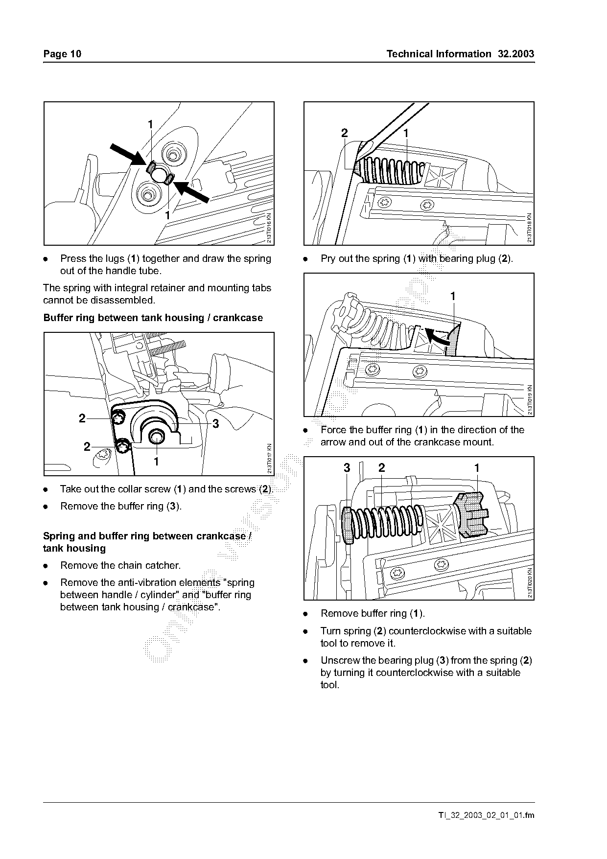
.   Press the lugs (1) together and draw the spring               .   Pry out the spring (1) with bearing plug (2).
    out of the handle tube.
The spring with integral retainer and mounting tabs

cannot be disassembled.                                                                              1
Buffer ring between tank housing / crankcase

                                                                                                                           213TI019 KN


                                      3                           .   Force the buffer ring (1) in the direction of the
                                                                      arrow and out of the crankcase mount.
          2
                                                    213TI017 KN


                                                                           3       2                      1

.   Take out the collar screw (1) and the screws (2).
.   Remove the buffer ring (3).

Spring and buffer ring between crankcase /
tank housing

.   Remove the chain catcher.
                                                                                                                           213TI020 KN

.   Remove the anti-vibration elements "spring
    between handle / cylinder" and "buffer ring

    between tank housing / crankcase".
                                                                  .   Remove buffer ring (1).
                                                                  .   Turn spring (2) counterclockwise with a suitable

                                                                      tool to remove it.
                                                                  .   Unscrew the bearing plug (3) from the spring (2)
                                                                      by turning it counterclockwise with a suitable
                                                                      tool.

                                                                                                  TI_32_2003_02_01_01.fm
Page 11 of 14
Text of page 11 — search, copy, screen readers
Technical Information 32.2003                                                                                        Page 11

4.2.2 Fitting anti-vibration elements                               Buffer ring between tank housing / crankcase
Spring and buffer ring between crankcase /
tank housing


                                                                            3                                1
    2
                                                                             3

                                                                                                                                  213TI024 KN
                                                                                               2

                                                      213TI021 KN
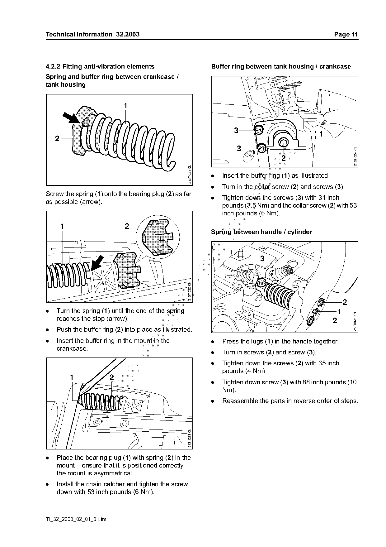
                                                                    .   Insert the buffer ring (1) as illustrated.

                                                                    .   Turn in the collar screw (2) and screws (3).
Screw the spring (1) onto the bearing plug (2) as far
                                                                    .   Tighten down the screws (3) with 31 inch
as possible (arrow).
                                                                        pounds (3.5 Nm) and the collar screw (2) with 53

                                                                        inch pounds (6 Nm).

        1                    2                                          fo
                                                                    Spring between handle / cylinder
                                                                                      3
                                                   -n 213TI022 KN


.   Turn the spring (1) until the end of the spring                                                                      1

                                                                                                                                 213TI025 KN
    reaches the stop (arrow).                                                                                        2
.   Push the buffer ring (2) into place as illustrated.

.   Insert the buffer ring in the mount in the                      .   Press the lugs (1) in the handle together.
    crankcase.
                                                                    .   Turn in screws (2) and screw (3).

                                                                    .   Tighten down the screws (2) with 35 inch
                                                                        pounds (4 Nm)
            1            2

                                                                    .   Tighten down screw (3) with 88 inch pounds (10
                                                                        Nm).
                                                                    .   Reassemble the parts in reverse order of steps.

                                                      213TI023 KN

.   Place the bearing plug (1) with spring (2) in the
    mount – ensure that it is positioned correctly –
    the mount is asymmetrical.
.   Install the chain catcher and tighten the screw
    down with 53 inch pounds (6 Nm).

TI_32_2003_02_01_01.fm
Page 12 of 14
Text of page 12 — search, copy, screen readers
Page 12                                                                              Technical Information 32.2003

4.3       Tank vent                                               Removing the tank vent
The tank vent ensures that the pressure inside the                .   Empty the fuel tank – if necessary, dispose of
fuel tank is equal to that outside. The tank vent must                the contents in accordance with regulations and
therefore be checked and replaced if necessary.                       without damaging the environment.
Check tank vent functioning                                       .   Remove the sprocket cover – remove the saw
.     Empty the fuel tank.                                            chain and guide bar if necessary – wear
                                                                      protective gloves.
.     Remove the carburetor.


                                                                                                                        213TI010 KN
      2

                                                    213TI009 KN

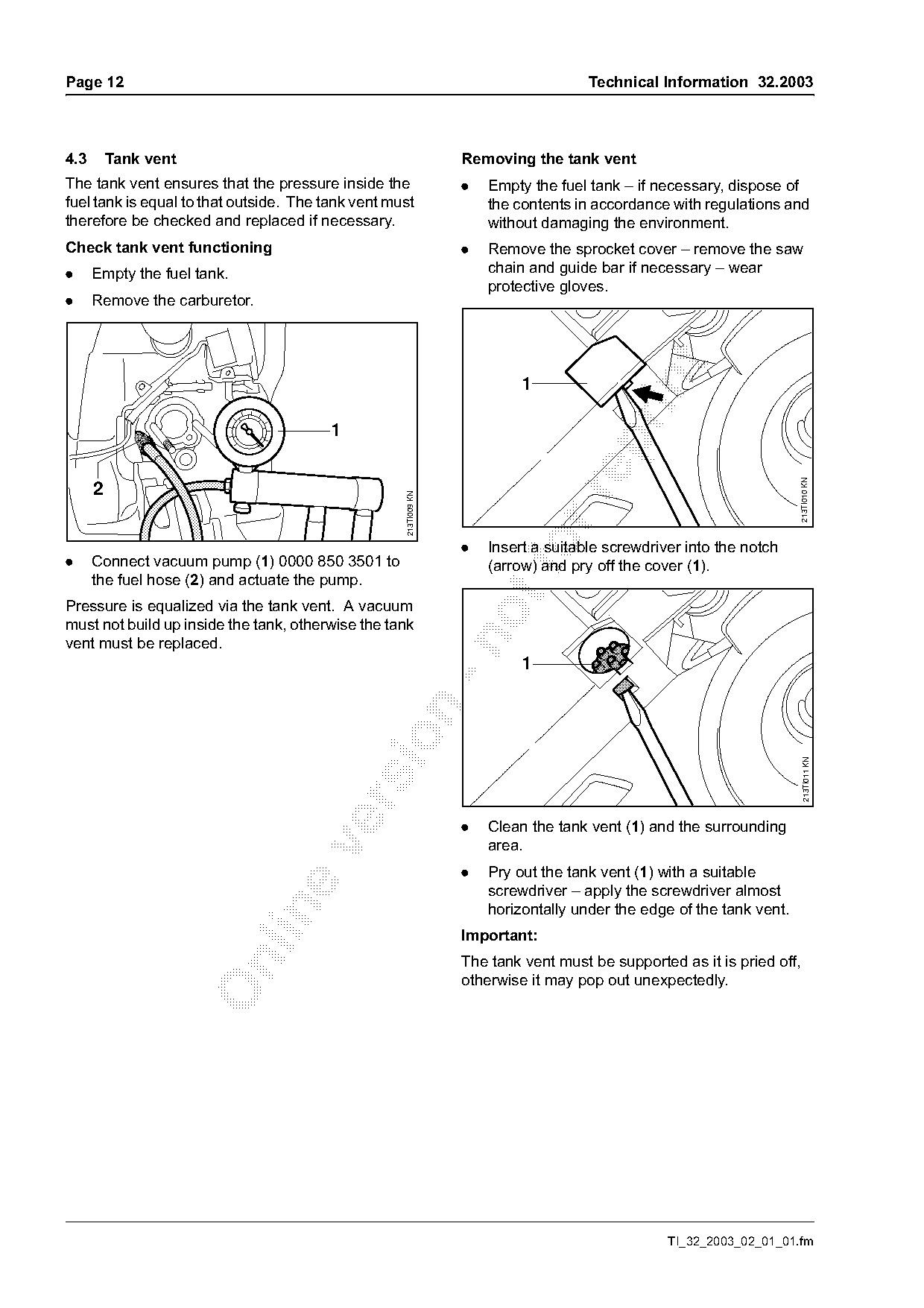
.     Connect vacuum pump (1) 0000 850 3501 to
                                                                  .       fo
                                                                      Insert a suitable screwdriver into the notch
                                                                      (arrow) and pry off the cover (1).
      the fuel hose (2) and actuate the pump.
Pressure is equalized via the tank vent. A vacuum
must not build up inside the tank, otherwise the tank

vent must be replaced.
                                                                           1

                                                                                                                          213TI011 KN

                                                                  .   Clean the tank vent (1) and the surrounding
                                                                      area.

                                                                  .   Pry out the tank vent (1) with a suitable
                                                                      screwdriver – apply the screwdriver almost
                                                                      horizontally under the edge of the tank vent.

                                                                  Important:
                                                                  The tank vent must be supported as it is pried off,

                                                                  otherwise it may pop out unexpectedly.

                                                                                                 TI_32_2003_02_01_01.fm
Page 13 of 14
Text of page 13 — search, copy, screen readers
Technical Information 32.2003                                                                                    Page 13

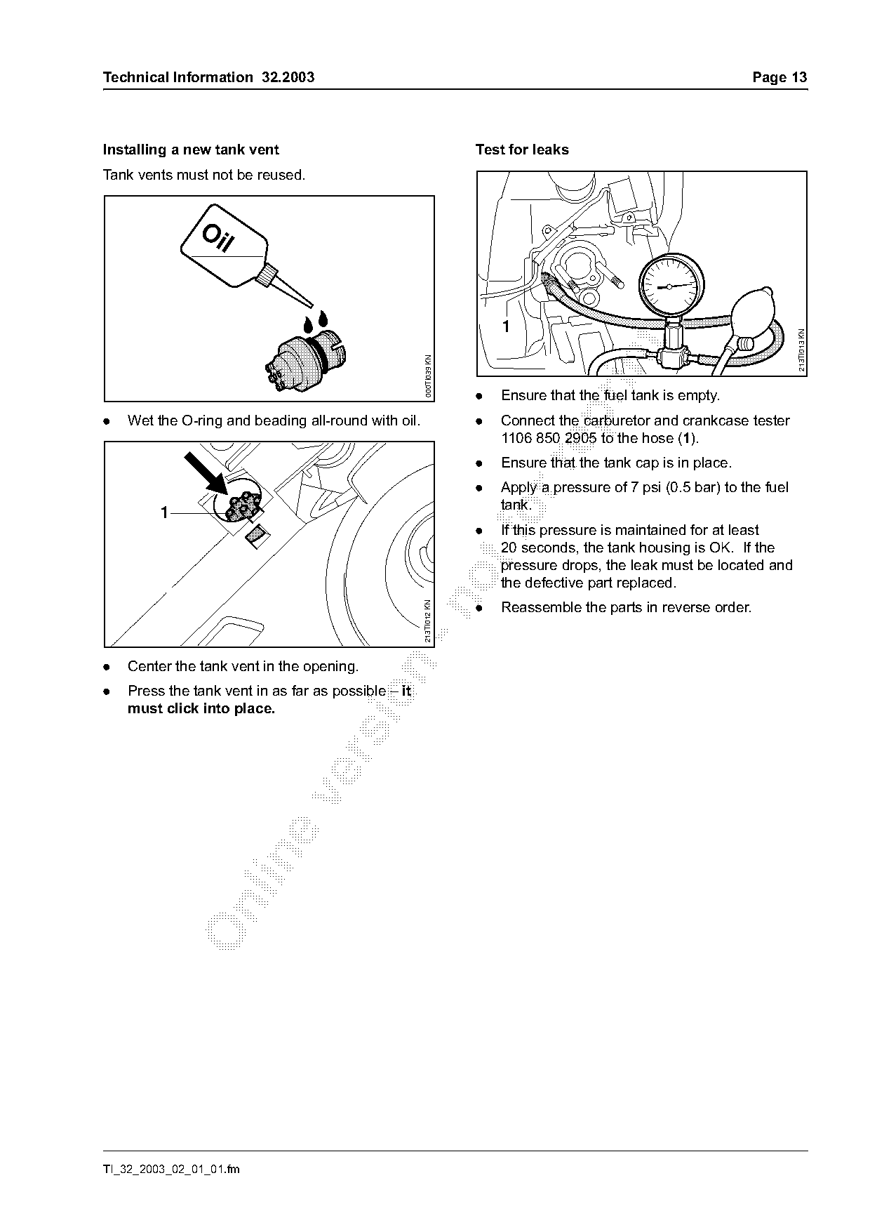
Installing a new tank vent                                          Test for leaks
Tank vents must not be reused.


                                                                                                                          213TI013 KN
                                                      000TI039 KN
                                                                    .   Ensure that the fuel tank is empty.

.   Wet the O-ring and beading all-round with oil.                  .   Connect the carburetor and crankcase tester
                                                                        1106 850 2905 to the hose (1).
                                                                    .   Ensure that the tank cap is in place.

                                                                    .   Apply a pressure of 7 psi (0.5 bar) to the fuel
                                                                        tank.
         1
                                                                    .
                                                                        If this pressure is maintained for at least
                                                                        20 seconds, the tank housing is OK. If the
                                                                        pressure drops, the leak must be located and
                                                                        the defective part replaced.

                                                                    .   Reassemble the parts in reverse order.
                                                     213TI012 KN

.   Center the tank vent in the opening.

.   Press the tank vent in as far as possible – it

    must click into place.

TI_32_2003_02_01_01.fm
Page 14 of 14
Text of page 14 — search, copy, screen readers
Page 14                                                                     Technical Information 32.2003

4.4   Tightening torques
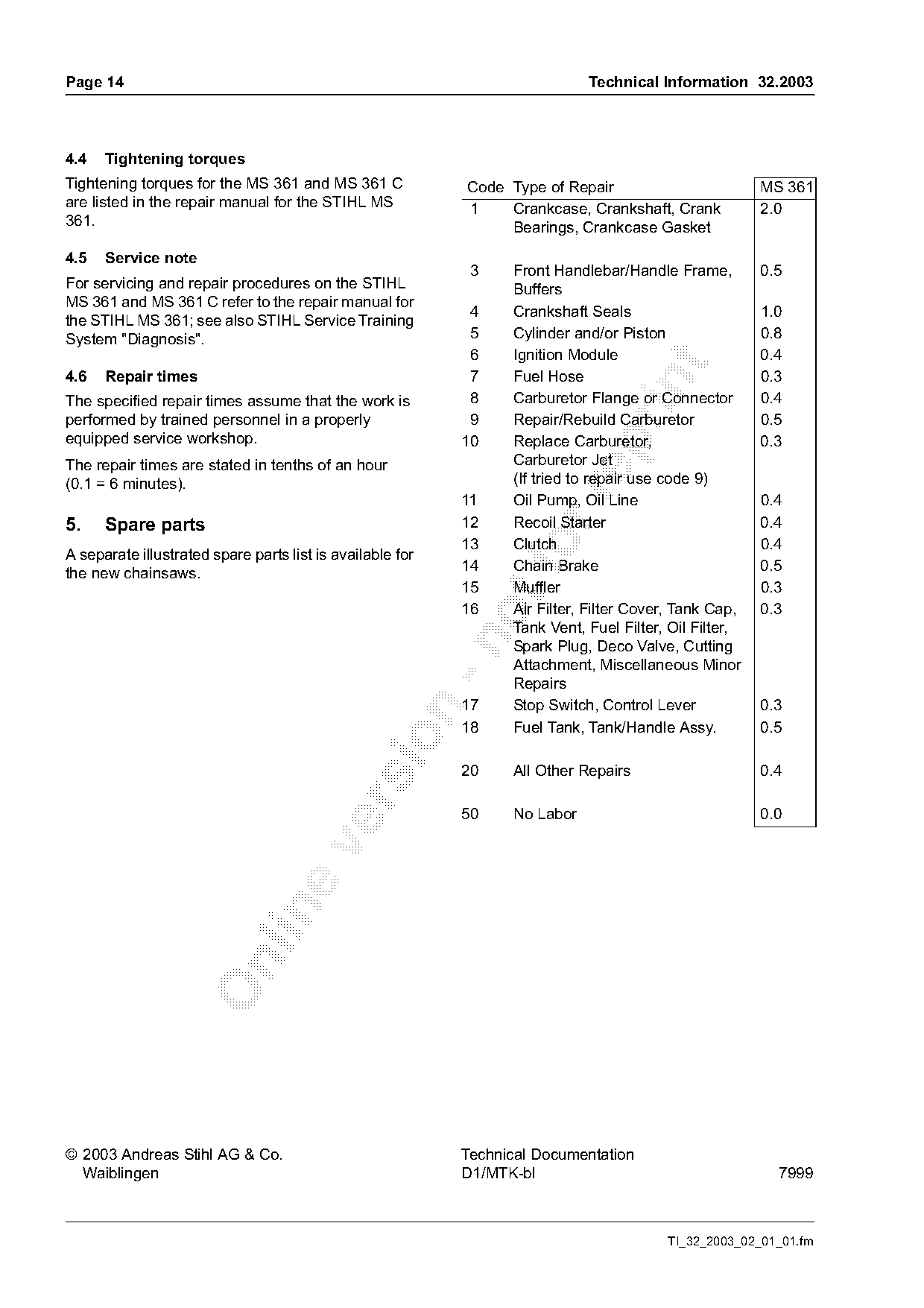
Tightening torques for the MS 361 and MS 361 C             Code Type of Repair                         MS 361
are listed in the repair manual for the STIHL MS           1    Crankcase, Crankshaft, Crank           2.0
361.                                                            Bearings, Crankcase Gasket
4.5   Service note
                                                            3    Front Handlebar/Handle Frame,         0.5
For servicing and repair procedures on the STIHL                 Buffers
MS 361 and MS 361 C refer to the repair manual for
                                                            4    Crankshaft Seals                      1.0
the STIHL MS 361; see also STIHL Service Training
System "Diagnosis".                                         5    Cylinder and/or Piston                0.8
                                                            6    Ignition Module                       0.4

4.6   Repair times                                          7    Fuel Hose                             0.3

The specified repair times assume that the work is          8    Carburetor Flange or Connector        0.4
performed by trained personnel in a properly                9    Repair/Rebuild Carburetor             0.5
equipped service workshop.                                 10    Replace Carburetor,                   0.3

The repair times are stated in tenths of an hour                 Carburetor Jet
(0.1 = 6 minutes).                                               (If tried to repair use code 9)

                                                           11    Oil Pump, Oil Line                    0.4
5.    Spare parts                                          12    Recoil Starter                        0.4

A separate illustrated spare parts list is available for
the new chainsaws.
                                                           13
                                                           14
                                                                 Clutch
                                                                 Chain Brake
                                                                                                       0.4
                                                                                                       0.5
                                                           15    Muffler                               0.3
                                                           16    Air Filter, Filter Cover, Tank Cap,   0.3
                                                                 Tank Vent, Fuel Filter, Oil Filter,

                                                                 Spark Plug, Deco Valve, Cutting
                                                                 Attachment, Miscellaneous Minor
                                                                 Repairs
                                                           17    Stop Switch, Control Lever            0.3

                                                           18    Fuel Tank, Tank/Handle Assy.          0.5

                                                           20    All Other Repairs                     0.4

                                                           50    No Labor                              0.0

© 2003 Andreas Stihl AG & Co.                              Technical Documentation
  Waiblingen                                               D1/MTK-bl                                     7999

                                                                                        TI_32_2003_02_01_01.fm
Most of these PDFs embed fonts with a shifted character map, so the text above was recovered rather than copied — read it as a faithful but imperfect transcription, and treat the page image above each block as the authority where the two disagree — the figures exist only there, because they are vector drawings that text extraction cannot keep.