Technical Information · issue 34 of 2003
General; General drawings; Control handle; Drive tube assembly; Gearhead; Pushrod and hook; Harness; Special tools
IssueTI 34/2003
Full text
Page 1 of 25
Text of page 1 — search, copy, screen readers
STIH)

Technical Information

                                                                     34.2003

  Service Notes for STIHL SP 200 Special Harvesters – Series 4233

  Contents
  1. General
     1.1 Preparing the surfaces to be joined
     1.2 Removing adhesive
  2. General drawings
  3. Control handle

     3.1 Disassembling and assembling the control handle
  4. Drive tube assembly
     4.1 Drive tube, engine end
     4.2 Swivel coupling

     4.3 Drive tube, gearhead end

  5. Gearhead
     5.1 Changing the gear oil
     5.2 Disassembling the gearbox
     5.3 Dismantling the gearbox

     5.4 Assembling the gearhead
     5.5 Attaching and lining up the gearhead

  6. Pushrod and hook
     6.1 Disassembling the pushrod
     6.2 Assembling the pushrod
     6.3 Hook

  7. Harness
     7.1 Attaching the harness

     7.2 Disassembling the eyes
     7.3 Assembling the eyes
  8. Special tools
     8.1 Set of service tools
     8.2 Illustrations of special tools

  TI_34_2003_01_01_01.fm                                                  englisch / English
Page 2 of 25

Text of page 2 — search, copy, screen readers
Page 2                                                                        Technical Information 34.2003

1.       General                                           .   Remove any grease, oil, dust or other dirt from
                                                               the surfaces to be joined, using an appropriate
Three different adhesives and an activator are used            solvent.
to secure screws and to join components on the
STIHL SP 200 special harvesters.                           .   Apply activator 7649 to one of the surfaces (or
                                                               to both surfaces if the gap is large) and
Part Number   Part Name                                        volatilize.
0786 110 0101 Loctite 243
                                                           .   Apply adhesive evenly along a length
              Threadlocker
                                                               corresponding to two-thirds of the overlapping
0786 110 1004 Loctite 326                                      surfaces. Cover the whole surface, starting at
              Fast-curing adhesive                             the beginning of the part with the outward-facing
0786 110 1005 Loctite 638                                      surface to be joined. This ensures that the

              Retaining compound                               adhesive is evenly distributed.

---           Loctite 7649
                                                           .   Slowly join the two surfaces together until they
              Activator for Loctite 326
                                                               are bearing on each other. Push and pull to

Some general instructions on the use of adhesives              distribute the adhesive evenly.
are therefore given to start with.                             Caution!
                                                               The working time is less than 60 seconds.

1.1      Preparing the surfaces to be joined               Disassembled parts:

1.1.1    Loctite 243 (threadlocker)                        .   Use sandpaper or similar to remove adhesive
New parts:
                                                           .
                                                               residues from the surfaces to be joined.
                                                               Then proceed as for new parts.
.     Remove any grease, oil, dust or other dirt from
      the inside and outside thread, using an
      appropriate solvent.
                                                           1.1.3   Loctite 638 (retaining compound)

.     Apply threadlocker evenly along a length             Threaded joints
      corresponding to half of the overlapping thread.
      Cover the whole surface, starting at the             New parts:
      beginning of the outside thread. This ensures

                                                           .   Remove any grease, oil, dust or other dirt from
      that the adhesive is evenly distributed.                 the inside and outside thread, using an

.     Assemble the threaded joint and tighten.                 appropriate solvent.

Disassembled parts:                                        .   Apply adhesive evenly along a length
                                                               corresponding to half of the overlapping thread.

.     Clean the thread with a wire brush or similar,           Cover the whole surface, starting at the
      taking care not to damage the flanks of the              beginning of the outside thread. This ensures
      thread.

                                                               that the adhesive is evenly distributed.
.     Then proceed as for new parts.                       .   Assemble the threaded joint and tighten.
                                                           Disassembled parts:

1.1.2    Loctite 326 (adhesive)                            .   Clean the thread with a wire brush or similar,
Activator 7649 is used to ensure even curing of the            taking care not to damage the flanks of the

bond. Homogeneous adhesion can therefore be                    thread.
expected, even in the case of larger bonded joints.        .   Then proceed as for new parts.
New parts:
.     The surfaces to be joined can be roughened           Plain bearings
      with fine sandpaper to improve adhesion.             New parts:
                                                           .   Remove any grease, oil, dust or other dirt from
                                                               the surfaces to be joined, using an appropriate
                                                               solvent.

                                                                                          TI_34_2003_01_01_01.fm
Page 3 of 25
Text of page 3 — search, copy, screen readers
Technical Information 34.2003                                                                      Page 3

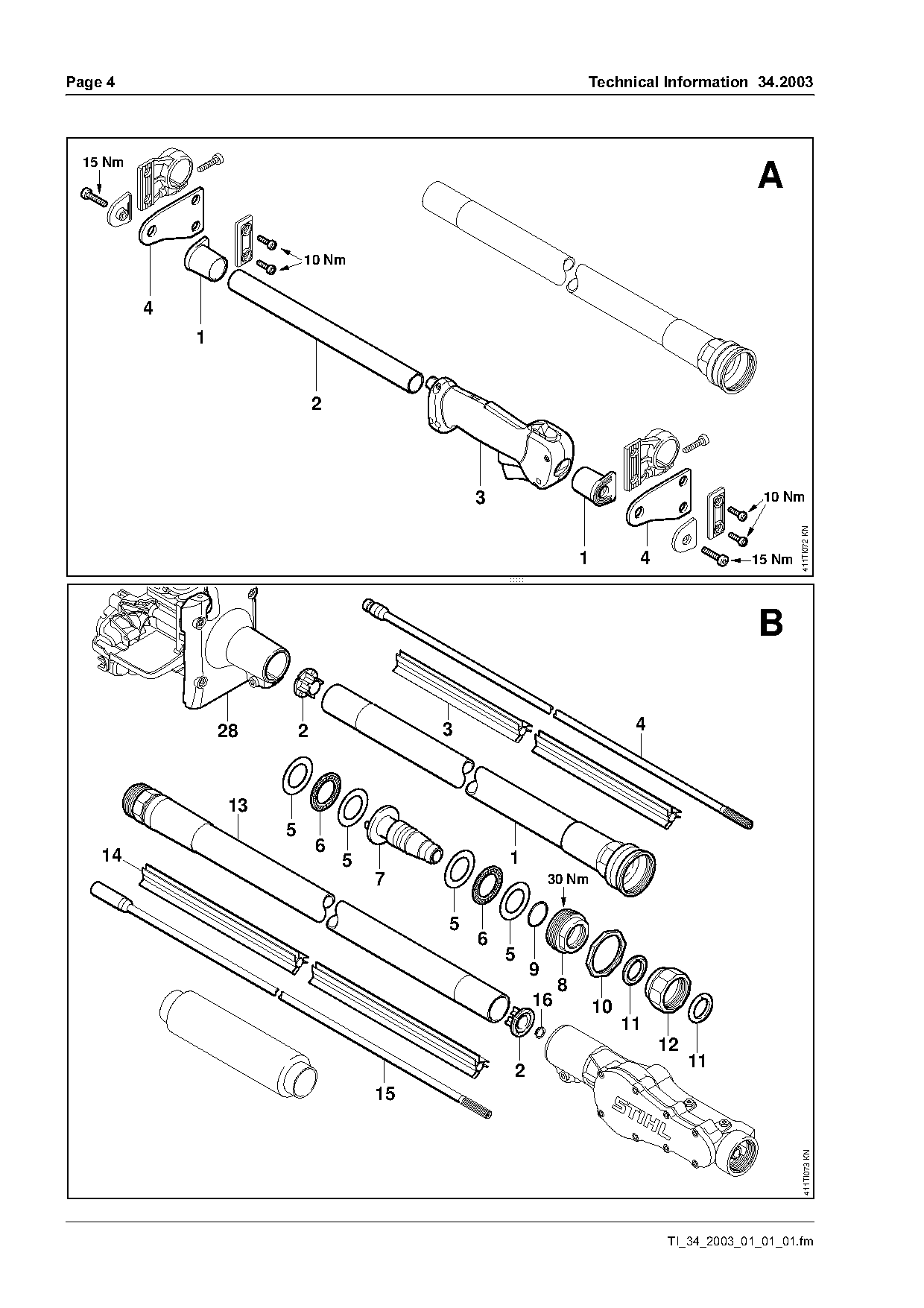
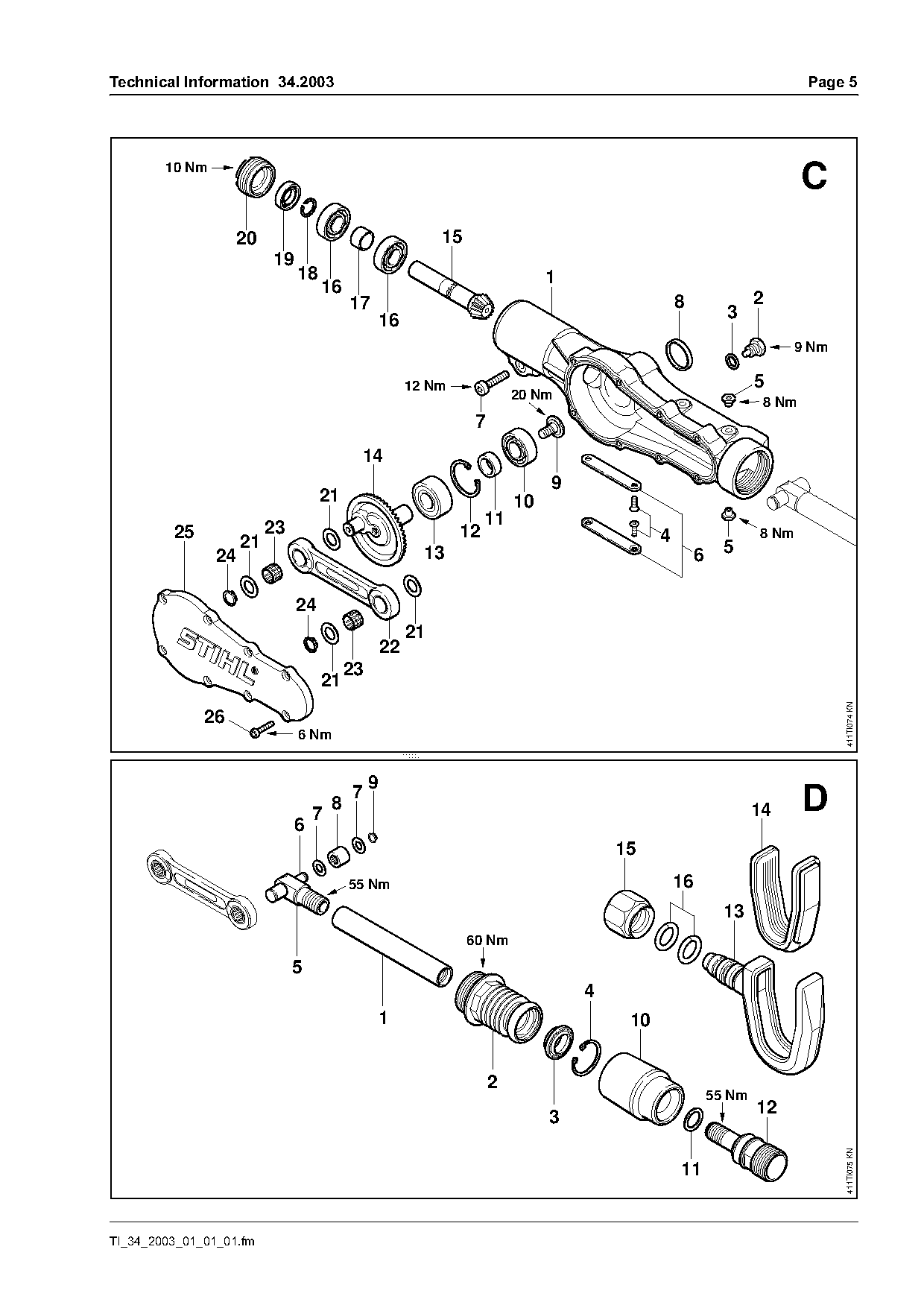
.     Apply adhesive to the whole of the outer ring of   2.     General drawings
      the bearing.
                                                         The drawings on the following pages can be copied
.     Insert bearing into bearing housing.               for use at the workbench.
.     Remove surplus adhesive, using an appropriate      A Control handle
      solvent.
                                                         B Drive tube assembly
Disassembled parts:
                                                         C Gearhead
.     Use sandpaper or similar to remove adhesive
      residues from the surfaces to be joined.           D Pushrod and hook

.     Then proceed as for new parts.

1.2      Removing adhesive
All the adhesives used can be removed by heat.

The use of an electric hot-air blower producing a hot
air jet at least 600 °C is recommended for releasing
bonds. This allows the bond area to be heated

quickly, without damaging other parts. The bond
areas should be heated as evenly as possible. A
slight crackling noise indicates that the bond is
loosening. Check frequently to see whether the
bond has loosened.
Caution! Contact with hot parts can cause burn
injuries.

TI_34_2003_01_01_01.fm
Page 4 of 25
Text of page 4 — search, copy, screen readers
Page 4                                                             Technical Information 34.2003

  15 Nm
                                                                                              A

                            10 Nm

          4
              1


                                                  3                                            10 Nm

                                                                                                     411TI072 KN
                                                      fo           1         4               15 Nm


                  28        2                 3                              4

                  13
                        5
                                6

    14                              5                 1
                                        7                     30 Nm

                                              5
                                                  6
                                                      5

                                                          9
                                                               8
                                                          16           10
                                                                            11
                                                                                 12
                                                                                      11
                                                      2
                                        15
                                                                                                      411TI073 KN

                                                                                 TI_34_2003_01_01_01.fm
Page 5 of 25
Text of page 5 — search, copy, screen readers
Technical Information 34.2003                                                                                               Page 5

        10 Nm
                                                                                                                            C
                   20                                         15
                          19
                               18                                                1
                                    16
                                           17                                                      8                2
                                                    16                                                        3
                                                                                                                         9 Nm


                                                         12 Nm
                                                                            20 Nm
                                                                                                                     8 Nm
                                                                    7

                                            14
                                                                                 9

                                    21                                      10
                          23                                          11
         25                                                      12                            4                    8 Nm
                     21                                                     fo                                5
                24                                         13                                           6
                               24
                                                         21

                                                    22
                                           23
                                    21

                                                                                                                                411TI074 KN

              26
                               6 Nm

                                                9
                                           7
                                                                                                                            D

                                       8                                                                            14
                                   7
                               6

                                                                                         15
                                           55 Nm                                                   16

                                                                                                              13
                                                                   60 Nm

                               5
                                                                                     4
                                                1                                         10

                                                                        2
                                                                                                            55 Nm
                                                                                                                    12
                                                                                 3
                                                                                                                                411TI075 KN


TI_34_2003_01_01_01.fm
Page 6 of 25
Text of page 6 — search, copy, screen readers
Page 6                                                              Technical Information 34.2003

3.        Control handle
See general drawing A.
Please refer to the general drawing for instructions
on disassembling and assembling the screwed
connections on the handle.

3.1       Disassembling and assembling the
          control handle
.     Unscrew the screws on the handle supports (1)
      and remove tube (2) and control handle (3).

.     Clamp the tube (2) and dissolve the adhesive on

      one of the handle supports (1) – see 1.2 – before
      removing the handle support.

.     Slacken the control handle (3) attachment
      screws and remove the control handle.
.     Also disassemble the second handle support (1)

      if necessary.
.     Attach control handle (3) to tube (2).
.     Apply Loctite 326 to tube (2) as described in
      chapter 1.1.2 and press the handle support (1)
      into place.

.     Line up the handle support (1).

.     Screw in and tighten the screws on the handle
      supports (1).

                                                                              TI_34_2003_01_01_01.fm
Page 7 of 25
Text of page 7 — search, copy, screen readers
Technical Information 34.2003                                                                                    Page 7

4.        Drive tube assembly
See general drawing B.
.     Slacken the union nut (12) using special tool
      4233 893 1300 and remove the front part of the
      drive tube from the machine. Use special tool
      4233 893 1302 to steady the drive tube at the
      gearhead end as you do so.

4.1       Drive tube, engine end

                                                                                                                           411TI078 KN
.     Slacken attachment screw on clutch housing.                                                          4

.     Slacken attachment screws on handle support

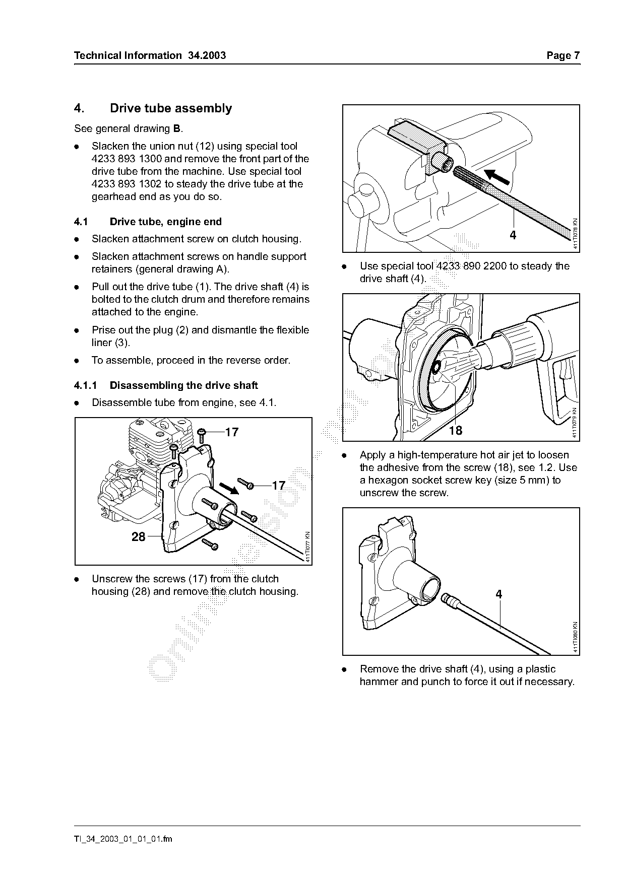
      retainers (general drawing A).                                  .   Use special tool 4233 890 2200 to steady the
                                                                          drive shaft (4).
.     Pull out the drive tube (1). The drive shaft (4) is

      bolted to the clutch drum and therefore remains
      attached to the engine.
.     Prise out the plug (2) and dismantle the flexible

      liner (3).
.     To assemble, proceed in the reverse order.

4.1.1     Disassembling the drive shaft
.     Disassemble tube from engine, see 4.1.

                                                                                                                         411TI079 KN
                                     17                                                      18

                                                                      .   Apply a high-temperature hot air jet to loosen
                                                                          the adhesive from the screw (18), see 1.2. Use
                                                                          a hexagon socket screw key (size 5 mm) to

                                                17
                                                                          unscrew the screw.
                                                        411TI077 KN


.     Unscrew the screws (17) from the clutch
      housing (28) and remove the clutch housing.                                                      4

                                                                                                                           411TI080 KN

                                                                      .   Remove the drive shaft (4), using a plastic
                                                                          hammer and punch to force it out if necessary.

TI_34_2003_01_01_01.fm
Page 8 of 25
Text of page 8 — search, copy, screen readers
Page 8                                                                                Technical Information 34.2003

4.1.2     Attaching the drive shaft
.     Place drive shaft (4) in position.
.     Apply Loctite 638 to the screw thread (18) as
      described in chapter 1.1.3.
      Take a hexagon socket screw key (size 5 mm),
      steadying the drive shaft with special tool
                                                                                                           8
      4233 890 2200, and screw in and tighten the                                                          10
      screw (18).
.     For further assembly operations, proceed in the

                                                                                                                        411TI069 KN
      reverse order to disassembly.

4.2       Swivel coupling
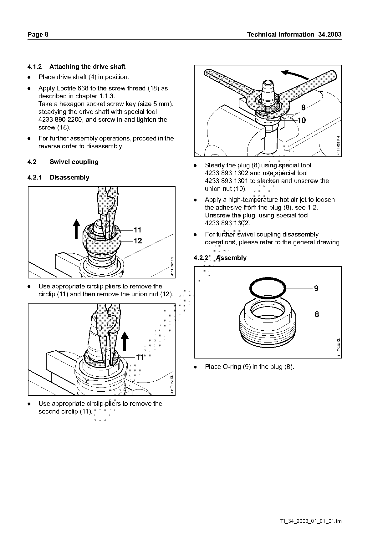
                                                                   .   Steady the plug (8) using special tool
                                                                       4233 893 1302 and use special tool
4.2.1     Disassembly
                                                                       4233 893 1301 to slacken and unscrew the

                                                                       union nut (10).
                                                                   .   Apply a high-temperature hot air jet to loosen
                                                                       the adhesive from the plug (8), see 1.2.

                                                                       Unscrew the plug, using special tool
                                                                       4233 893 1302.
                                           11
                                           12
                                                                   .
                                                                       For further swivel coupling disassembly
                                                                       operations, please refer to the general drawing.
                                                                   4.2.2   Assembly
                                                     411TI067 KN

.     Use appropriate circlip pliers to remove the                                                              9
      circlip (11) and then remove the union nut (12).


                                                                                                                        411TI036 KN

                                           11
                                                                   .   Place O-ring (9) in the plug (8).
                                                     411TI068 KN

.     Use appropriate circlip pliers to remove the

      second circlip (11).

                                                                                                  TI_34_2003_01_01_01.fm
Page 9 of 25
Text of page 9 — search, copy, screen readers
Technical Information 34.2003                                                                                     Page 9


             8
                                                                                        19                           11

                                                    411TI037 KN

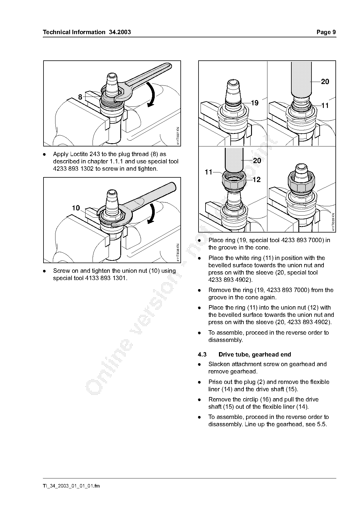
.   Apply Loctite 243 to the plug thread (8) as
    described in chapter 1.1.1 and use special tool                                      20
    4233 893 1302 to screw in and tighten.
                                                                      11


                                                                                                                          411TI039 KN
                                                                  .     Place ring (19, special tool 4233 893 7000) in
                                                    411TI038 KN

                                                                        the groove in the cone.

                                                                  .     Place the white ring (11) in position with the
                                                                        bevelled surface towards the union nut and
.   Screw on and tighten the union nut (10) using                       press on with the sleeve (20, special tool
    special tool 4133 893 1301.

                                                                        4233 893 4902).

                                                                  .     Remove the ring (19, 4233 893 7000) from the
                                                                        groove in the cone again.
                                                                  .     Place the ring (11) into the union nut (12) with
                                                                        the bevelled surface towards the union nut and

                                                                        press on with the sleeve (20, 4233 893 4902).

                                                                  .     To assemble, proceed in the reverse order to
                                                                        disassembly.

                                                                  4.3       Drive tube, gearhead end

                                                                  .     Slacken attachment screw on gearhead and
                                                                        remove gearhead.

                                                                  .     Prise out the plug (2) and remove the flexible
                                                                        liner (14) and the drive shaft (15).
                                                                  .     Remove the circlip (16) and pull the drive
                                                                        shaft (15) out of the flexible liner (14).
                                                                  .     To assemble, proceed in the reverse order to
                                                                        disassembly. Line up the gearhead, see 5.5.

TI_34_2003_01_01_01.fm
Page 10 of 25
Text of page 10 — search, copy, screen readers
Page 10                                                                                    Technical Information 34.2003

5.       Gearhead                                                     5.3       Dismantling the gearbox

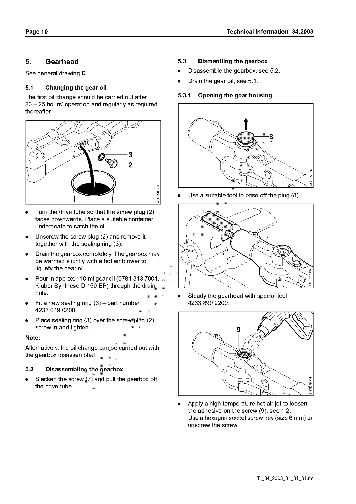
See general drawing C.                                                .     Disassemble the gearbox, see 5.2.
                                                                      .     Drain the gear oil, see 5.1.
5.1      Changing the gear oil
The first oil change should be carried out after                      5.3.1     Opening the gear housing
20 – 25 hours’ operation and regularly as required
thereafter.


                                          3
                                          2

                                                                                                                                411TI050 KN
                                                        411TI047 KN

                                                                      .     Use a suitable tool to prise off the plug (8).

.     Turn the drive tube so that the screw plug (2)
      faces downwards. Place a suitable container
      underneath to catch the oil.
.     Unscrew the screw plug (2) and remove it
      together with the sealing ring (3).

.     Drain the gearbox completely. The gearbox may
      be warmed slightly with a hot air blower to
      liquefy the gear oil.

                                                                                                                             411TI016 KN

.     Pour in approx. 110 ml gear oil (0781 313 7001,

      Klüber Syntheso D 150 EP) through the drain
      hole.
                                                                      .     Steady the gearhead with special tool
.     Fit a new sealing ring (3) – part number                              4233 890 2200.

      4233 649 0200
.     Place sealing ring (3) over the screw plug (2),

      screw in and tighten.                                                                    9
Note:
Alternatively, the oil change can be carried out with

the gearbox disassembled.

5.2      Disassembling the gearbox

.     Slacken the screw (7) and pull the gearbox off
                                                                                                                               411TI076 KN

      the drive tube.

                                                                      .     Apply a high-temperature hot air jet to loosen
                                                                            the adhesive on the screw (9), see 1.2.
                                                                            Use a hexagon socket screw key (size 6 mm) to
                                                                            unscrew the screw.

                                                                                                        TI_34_2003_01_01_01.fm
Page 11 of 25
Text of page 11 — search, copy, screen readers
Technical Information 34.2003                                                                                    Page 11


                                                                                                                         411TI051 KN
                                                      411TI046 KN

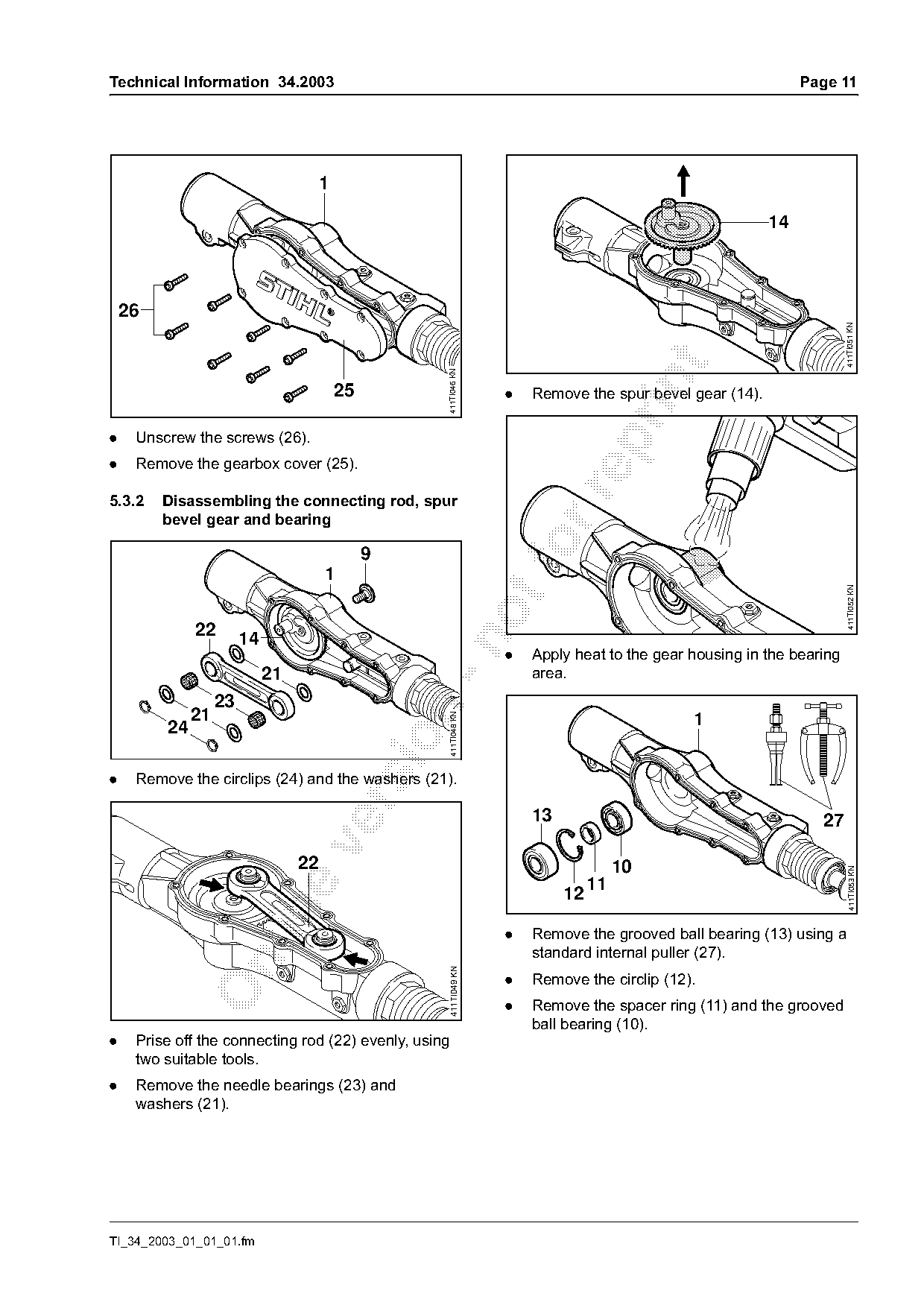
                                           25                        .   Remove the spur bevel gear (14).

.    Unscrew the screws (26).

.    Remove the gearbox cover (25).

5.3.2    Disassembling the connecting rod, spur
         bevel gear and bearing

                                       1
                                                9                        fo

                                                                                                                         411TI052 KN

              22        14

                                                                     .   Apply heat to the gear housing in the bearing
                             21                                          area.
                   23

              21
                                                       411TI048 KN

         24                                                                                     1

.    Remove the circlips (24) and the washers (21).

                                                                         13                                        27

                                  22                                                    10
                                                                                                                           411TI053 KN

                                                                                   11
                                                                              12

                                                                     .   Remove the grooved ball bearing (13) using a
                                                                         standard internal puller (27).

                                                       411TI049 KN

                                                                     .   Remove the circlip (12).
                                                                     .   Remove the spacer ring (11) and the grooved
                                                                         ball bearing (10).
.    Prise off the connecting rod (22) evenly, using
     two suitable tools.
.    Remove the needle bearings (23) and
     washers (21).

TI_34_2003_01_01_01.fm
Page 12 of 25
Text of page 12 — search, copy, screen readers
Page 12                                                                                  Technical Information 34.2003

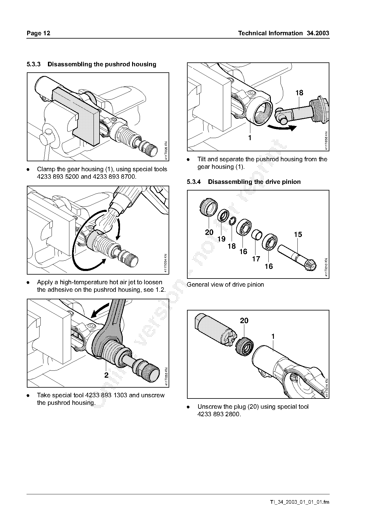
5.3.3   Disassembling the pushrod housing


                                                                                                                        411TI056 KN
                                                                                              1

                                                   411TI026 KN

                                                                  .   Tilt and separate the pushrod housing from the
.   Clamp the gear housing (1), using special tools                   gear housing (1).
    4233 893 5200 and 4233 893 8700.

                                                                  5.3.4   Disassembling the drive pinion

                                                                          20                                15
                                                                               19
                                                                                    18
                                                                                         16
                                                 411TI054 KN


                                                                                                                         411TI010 KN
                                                                                                   16

.   Apply a high-temperature hot air jet to loosen                General view of drive pinion

    the adhesive on the pushrod housing, see 1.2.


                                                    411TI055 KN

                            2
                                                                                                                          411TI014 KN

.   Take special tool 4233 893 1303 and unscrew
    the pushrod housing.
                                                                  .   Unscrew the plug (20) using special tool
                                                                      4233 893 2800.

                                                                                                    TI_34_2003_01_01_01.fm
Page 13 of 25
Text of page 13 — search, copy, screen readers
Technical Information 34.2003                                                                                 Page 13

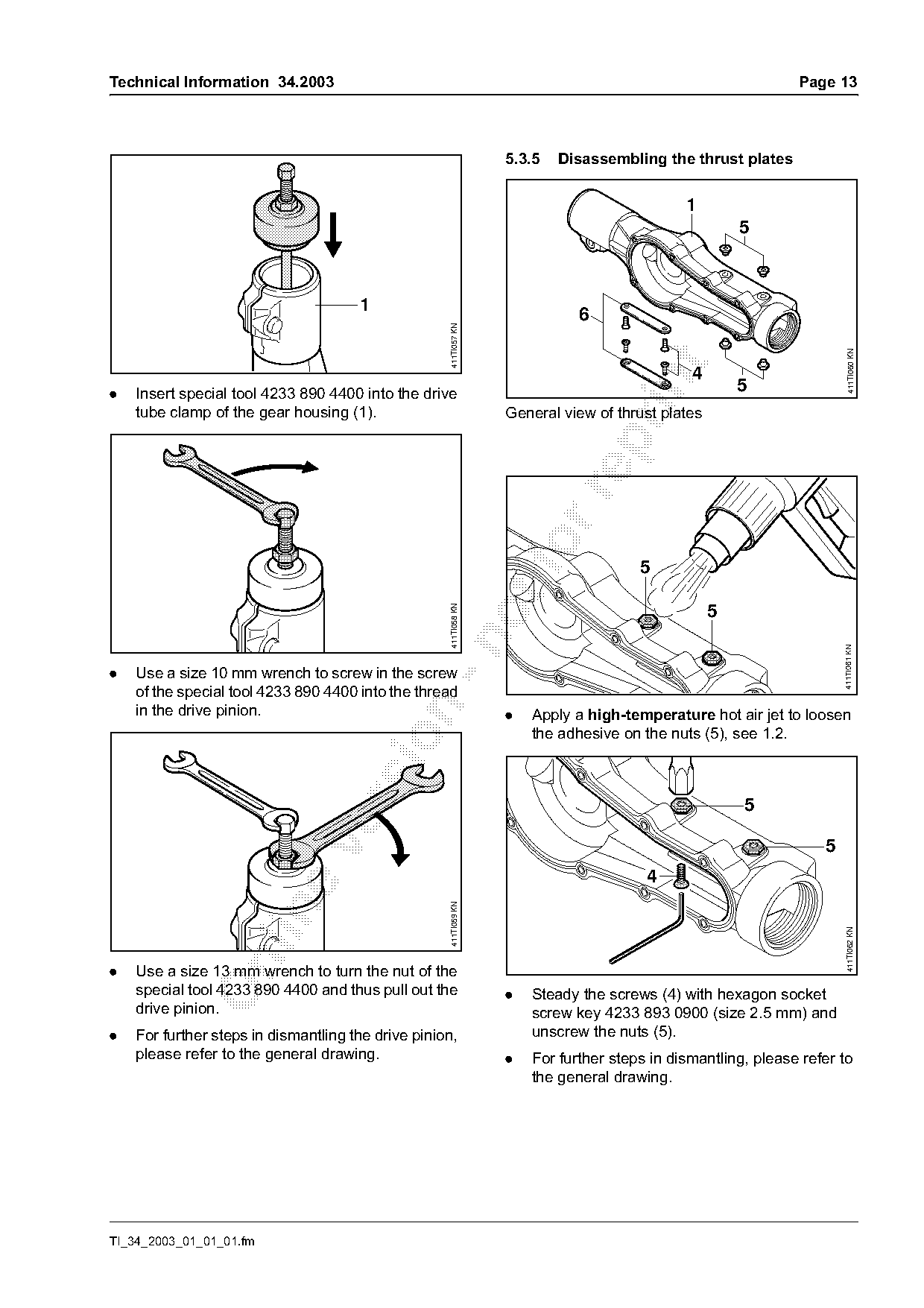
                                                                  5.3.5   Disassembling the thrust plates

                                                                                             1
                                                                                                      5

                                      1
                                                                             6

                                                    411TI057 KN

                                                                                                                         411TI060 KN
                                                                                              4

.   Insert special tool 4233 890 4400 into the drive
                                                                                                      5
    tube clamp of the gear housing (1).                           General view of thrust plates

                                                                      fo              5
                                                    411TI058 KN


                                                                                                                      411TI061 KN
.   Use a size 10 mm wrench to screw in the screw
    of the special tool 4233 890 4400 into the thread
    in the drive pinion.

                                                                  .   Apply a high-temperature hot air jet to loosen
                                                                      the adhesive on the nuts (5), see 1.2.


                                                                                                                  5
                                                                                       4
                                                    411TI059 KN

                                                                                                                        411TI062 KN

.   Use a size 13 mm wrench to turn the nut of the
    special tool 4233 890 4400 and thus pull out the              .   Steady the screws (4) with hexagon socket
    drive pinion.                                                     screw key 4233 893 0900 (size 2.5 mm) and
.   For further steps in dismantling the drive pinion,                unscrew the nuts (5).
    please refer to the general drawing.                          .   For further steps in dismantling, please refer to
                                                                      the general drawing.

TI_34_2003_01_01_01.fm
Page 14 of 25
Text of page 14 — search, copy, screen readers
Page 14                                                                                 Technical Information 34.2003

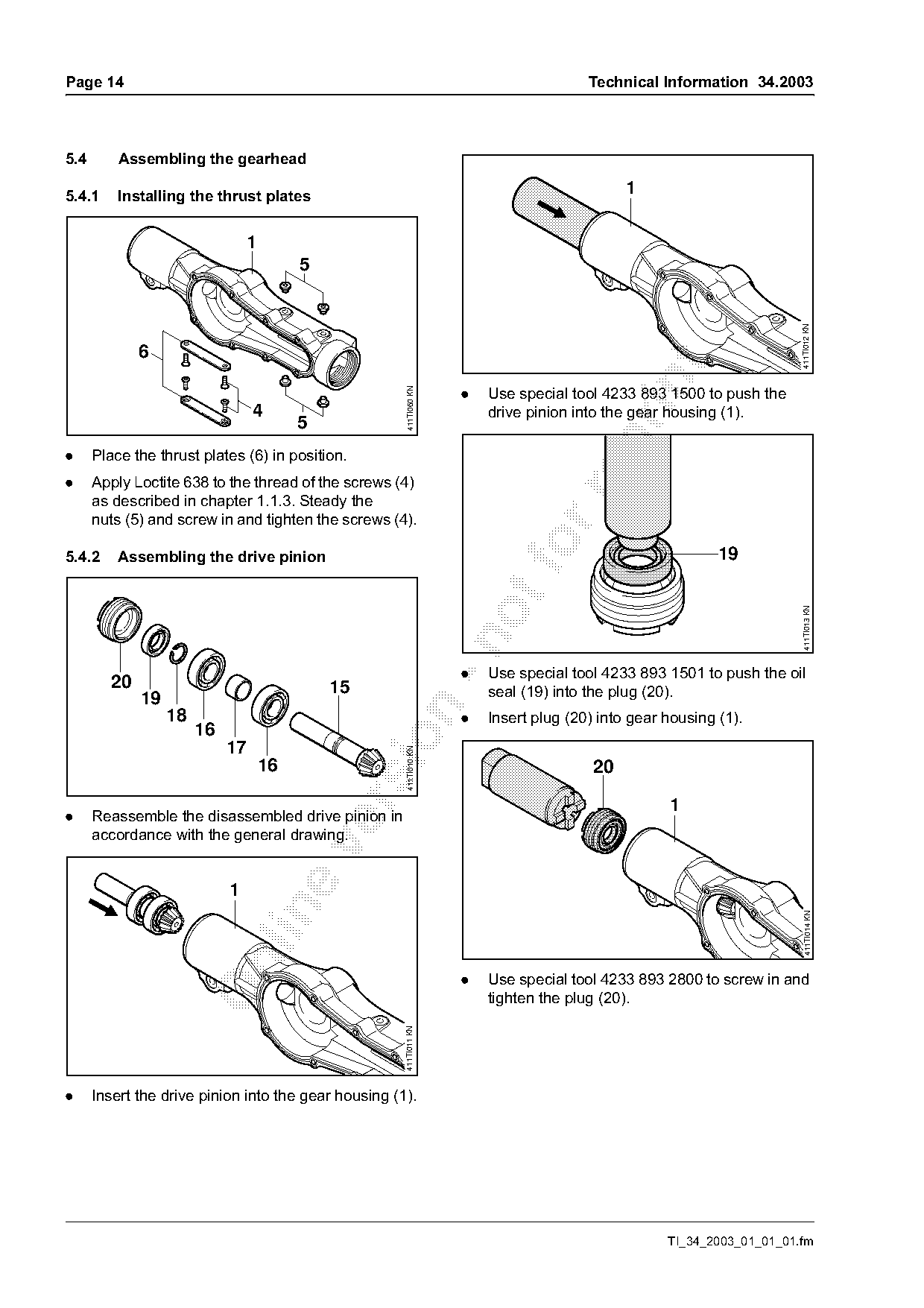
5.4       Assembling the gearhead

5.4.1     Installing the thrust plates
                                                                                              1

                                1
                                         5

                                                                                                                        411TI012 KN
             6

                                                                     .   Use special tool 4233 893 1500 to push the
                                                       411TI060 KN
                                 4                                       drive pinion into the gear housing (1).
                                         5

.     Place the thrust plates (6) in position.
.     Apply Loctite 638 to the thread of the screws (4)

      as described in chapter 1.1.3. Steady the
      nuts (5) and screw in and tighten the screws (4).

5.4.2     Assembling the drive pinion                                        fo                             19

                                                                                                                         411TI013 KN

                                                                     .   Use special tool 4233 893 1501 to push the oil
        20                                   15                          seal (19) into the plug (20).
             19

                  18                                                 .   Insert plug (20) into gear housing (1).
                       16

                            17
                                                       411TI010 KN

                                    16                                                   20

                                                                                                    1
.     Reassemble the disassembled drive pinion in
      accordance with the general drawing.


                                                                                                                          411TI014 KN

                                                                     .   Use special tool 4233 893 2800 to screw in and
                                                                         tighten the plug (20).
                                                      411TI011 KN

.     Insert the drive pinion into the gear housing (1).

                                                                                                    TI_34_2003_01_01_01.fm
Page 15 of 25
Text of page 15 — search, copy, screen readers
Technical Information 34.2003                                                                                  Page 15

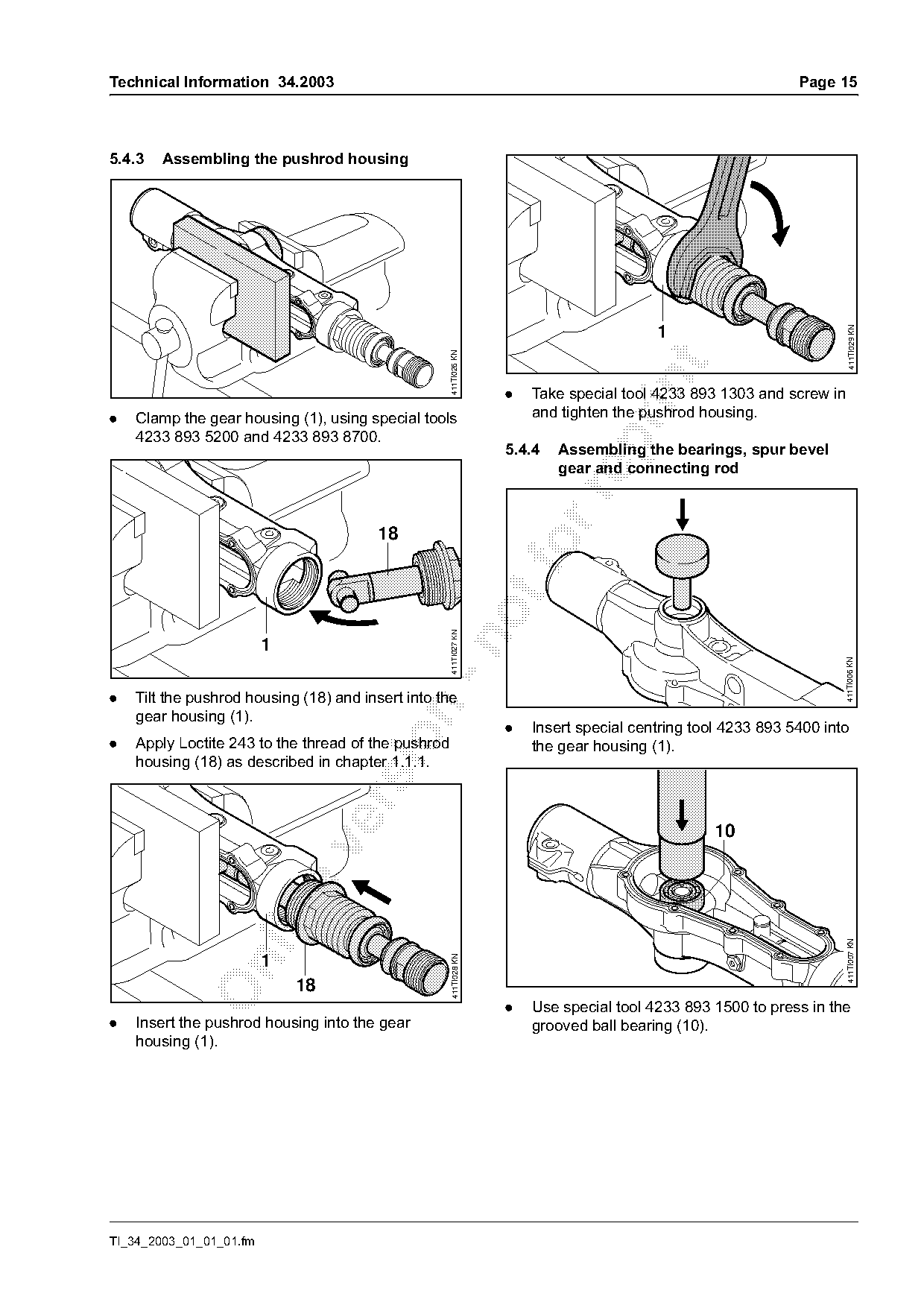
5.4.3   Assembling the pushrod housing


                                                                                                                         411TI029 KN
                                                     411TI026 KN

                                                                    .   Take special tool 4233 893 1303 and screw in
.   Clamp the gear housing (1), using special tools                     and tighten the pushrod housing.
    4233 893 5200 and 4233 893 8700.

                                                                    5.4.4   Assembling the bearings, spur bevel
                                                                            gear and connecting rod

                                        18
                                                     411TI027 KN


                                                                                                                       411TI006 KN
.   Tilt the pushrod housing (18) and insert into the

    gear housing (1).
                                                                    .   Insert special centring tool 4233 893 5400 into

.   Apply Loctite 243 to the thread of the pushrod                      the gear housing (1).
    housing (18) as described in chapter 1.1.1.


                                                                                                                       411TI007 KN

                         1
                                                      411TI028 KN

                             18
                                                                    .   Use special tool 4233 893 1500 to press in the
.   Insert the pushrod housing into the gear                            grooved ball bearing (10).
    housing (1).

TI_34_2003_01_01_01.fm
Page 16 of 25
Text of page 16 — search, copy, screen readers
Page 16                                                                                  Technical Information 34.2003

                               12
                                                                                                    1


                                                                                            21
                                                                                    23
                                                                               21

                                                                                                                         411TI031 KN
                                                   411TI008 KN
                                                                          24

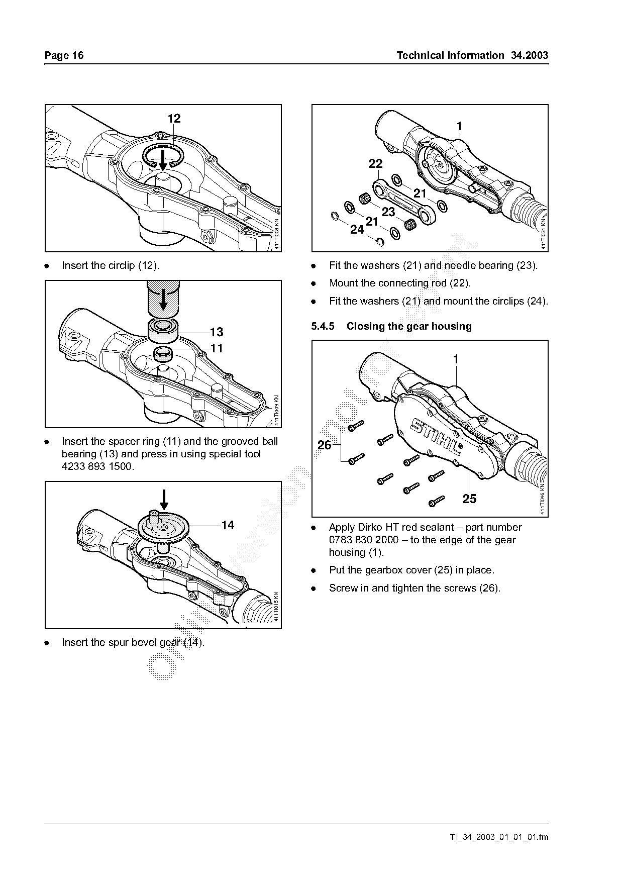
.   Insert the circlip (12).                                     .    Fit the washers (21) and needle bearing (23).
                                                                 .    Mount the connecting rod (22).

                                                                 .    Fit the washers (21) and mount the circlips (24).

                                                                 5.4.5    Closing the gear housing
                                       13

                                       11
                                                                                                   1
                                                   411TI009 KN

.   Insert the spacer ring (11) and the grooved ball                 26
    bearing (13) and press in using special tool
    4233 893 1500.

                                                                                                                       411TI046 KN


                                        14                       .    Apply Dirko HT red sealant – part number
                                                                      0783 830 2000 – to the edge of the gear

                                                                      housing (1).
                                                                 .    Put the gearbox cover (25) in place.

                                                                 .    Screw in and tighten the screws (26).
                                                   411TI015 KN

.   Insert the spur bevel gear (14).

                                                                                                   TI_34_2003_01_01_01.fm
Page 17 of 25
Text of page 17 — search, copy, screen readers
Technical Information 34.2003                                                                                    Page 17

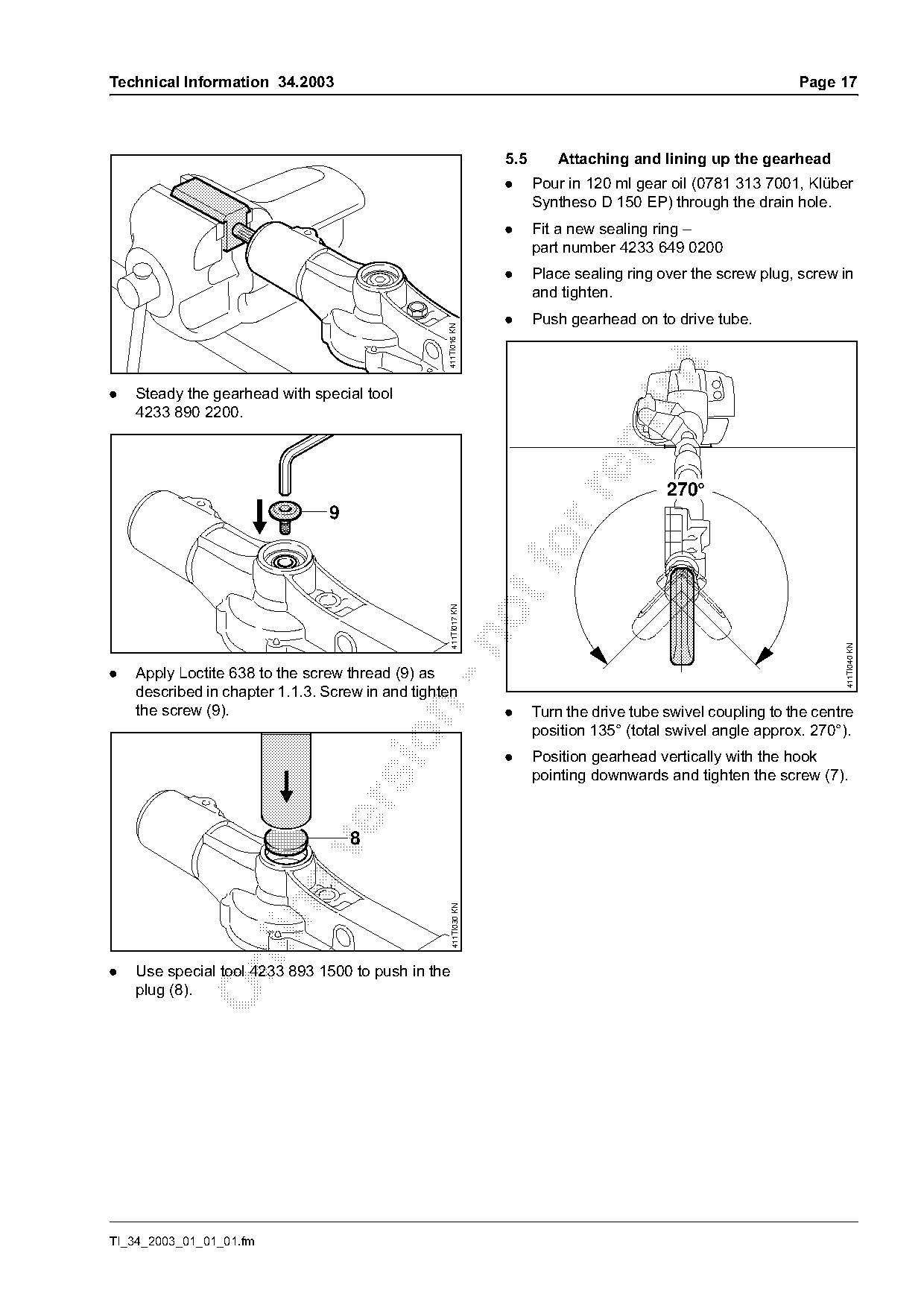
                                                                   5.5       Attaching and lining up the gearhead
                                                                   .     Pour in 120 ml gear oil (0781 313 7001, Klüber
                                                                         Syntheso D 150 EP) through the drain hole.
                                                                   .     Fit a new sealing ring –
                                                                         part number 4233 649 0200
                                                                   .     Place sealing ring over the screw plug, screw in
                                                                         and tighten.
                                                                   .     Push gearhead on to drive tube.

                                                  411TI016 KN

.   Steady the gearhead with special tool
    4233 890 2200.

                                                                                             270°


                                                    411TI017 KN

                                                                                                                        411TI040 KN
.   Apply Loctite 638 to the screw thread (9) as
    described in chapter 1.1.3. Screw in and tighten
    the screw (9).

                                                                   .     Turn the drive tube swivel coupling to the centre
                                                                         position 135° (total swivel angle approx. 270°).

                                                                   .     Position gearhead vertically with the hook
                                                                         pointing downwards and tighten the screw (7).


                                                     411TI030 KN

.   Use special tool 4233 893 1500 to push in the
    plug (8).

TI_34_2003_01_01_01.fm
Page 18 of 25
Text of page 18 — search, copy, screen readers
Page 18                                                                                  Technical Information 34.2003

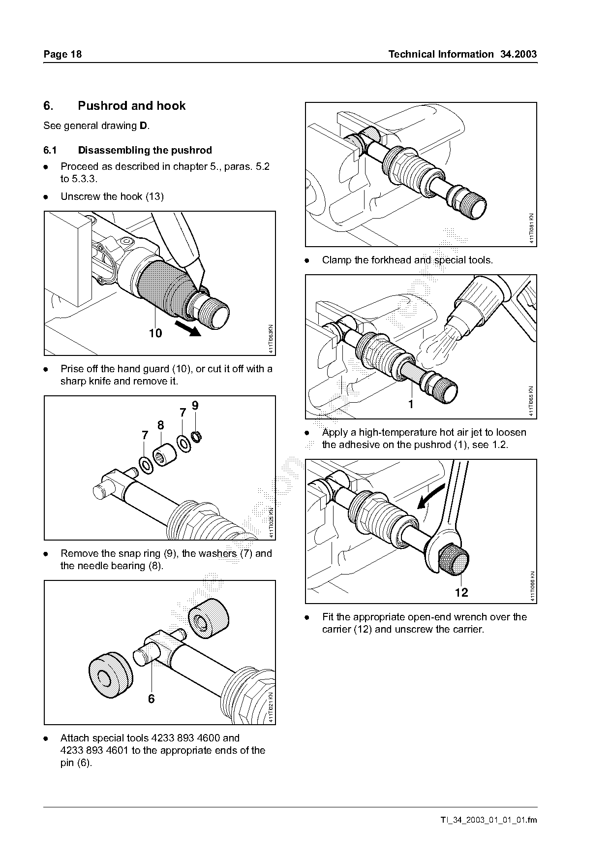
6.        Pushrod and hook
See general drawing D.

6.1       Disassembling the pushrod
.     Proceed as described in chapter 5., paras. 5.2
      to 5.3.3.
.     Unscrew the hook (13)

                                                                                                                            411TI081 KN
                                                                       .   Clamp the forkhead and special tools.

                                                        411TI063KN


.     Prise off the hand guard (10), or cut it off with a
      sharp knife and remove it.

                                                                                                                            411TI065 KN
                                       9                                                      1
                                   7

                               8
                         7                                             .   Apply a high-temperature hot air jet to loosen
                                                                           the adhesive on the pushrod (1), see 1.2.
                                                sio      411TI025 KN

.     Remove the snap ring (9), the washers (7) and

      the needle bearing (8).
                                                                                                                              411TI066 KN


                                                                       .   Fit the appropriate open-end wrench over the
                                                                           carrier (12) and unscrew the carrier.

                                                        411TI021 KN


.     Attach special tools 4233 893 4600 and
      4233 893 4601 to the appropriate ends of the
      pin (6).

                                                                                                     TI_34_2003_01_01_01.fm
Page 19 of 25
Text of page 19 — search, copy, screen readers
Technical Information 34.2003                                                                                   Page 19

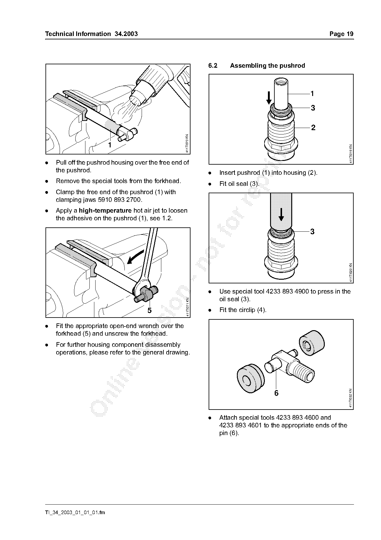
                                                                   6.2       Assembling the pushrod

                                                                                                          1
                                                                                                          3


                                                   411TI070 KN
                         1

                                                                                                                         411TI019 KN
.   Pull off the pushrod housing over the free end of
    the pushrod.                                                   .     Insert pushrod (1) into housing (2).
.   Remove the special tools from the forkhead.

                                                                   .     Fit oil seal (3).
.   Clamp the free end of the pushrod (1) with
    clamping jaws 5910 893 2700.

.   Apply a high-temperature hot air jet to loosen
    the adhesive on the pushrod (1), see 1.2.
                                                                       fo                                 3

                                                                                                                         411TI020 KN
                                                                   .     Use special tool 4233 893 4900 to press in the

                                                                         oil seal (3).
                                                     411TI071 KN

                                     5                             .     Fit the circlip (4).

.   Fit the appropriate open-end wrench over the

    forkhead (5) and unscrew the forkhead.
.   For further housing component disassembly

    operations, please refer to the general drawing.

                                                                                                                        411TI032 KN


                                                                   .     Attach special tools 4233 893 4600 and
                                                                         4233 893 4601 to the appropriate ends of the
                                                                         pin (6).

TI_34_2003_01_01_01.fm
Page 20 of 25
Text of page 20 — search, copy, screen readers
Page 20                                                                                Technical Information 34.2003

                                                                                                       9
                                                                                                   7
                                                                                              8
                                                                                          7

                                                     411TI022 KN

                                                                                                                        411TI025 KN
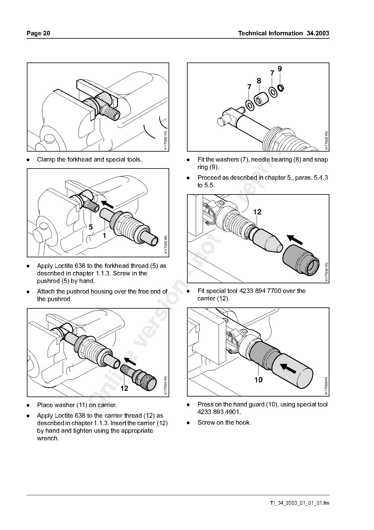
.   Clamp the forkhead and special tools.                           .   Fit the washers (7), needle bearing (8) and snap
                                                                        ring (9).
                                                                    .   Proceed as described in chapter 5., paras. 5.4.3

                                                                        to 5.5.


                        5
                             1
                                                      411TI023 KN

.   Apply Loctite 638 to the forkhead thread (5) as

                                                                                                                        411TI034 KN
    described in chapter 1.1.3. Screw in the
    pushrod (5) by hand.

.   Attach the pushrod housing over the free end of                 .   Fit special tool 4233 894 7700 over the
    the pushrod.                                                        carrier (12).

                                                     411TI024 KN

                                                                                              10
                                                                                                                       411TI035KN


.   Place washer (11) on carrier.                                   .   Press on the hand guard (10), using special tool
                                                                        4233 893 4901.
.   Apply Loctite 638 to the carrier thread (12) as
    described in chapter 1.1.3. Insert the carrier (12)             .   Screw on the hook.
    by hand and tighten using the appropriate
    wrench.

                                                                                                   TI_34_2003_01_01_01.fm
Page 21 of 25
Text of page 21 — search, copy, screen readers
Technical Information 34.2003                                                      Page 21

6.3       Hook
.     Unscrew the hook.

6.3.1     Rubber insert
.     Prise the rubber insert (14) out of the hook. Fit a
      new rubber insert.
.     Screw on the hook and line it up.

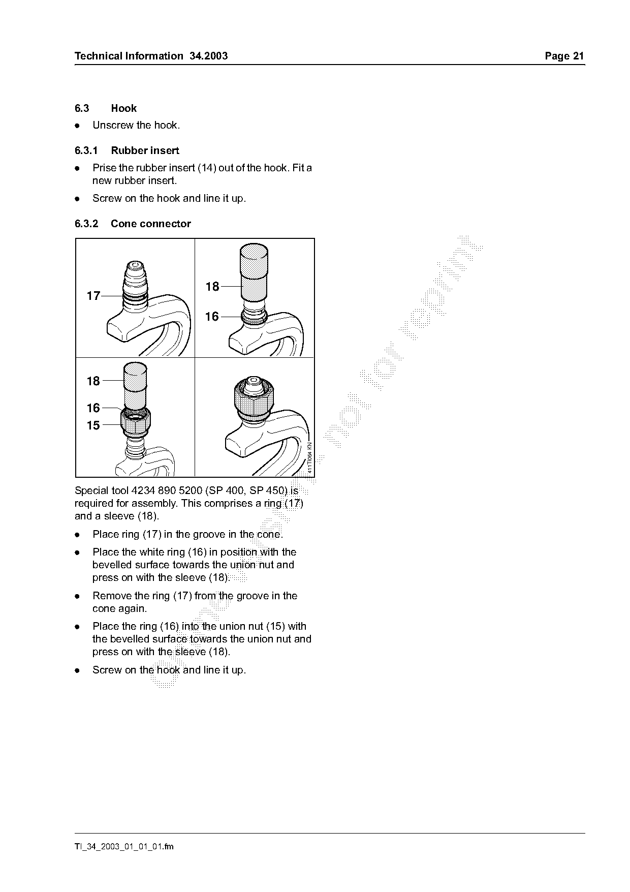
6.3.2     Cone connector

                                18
    17


    18
    16
    15
                                                       411TI064 KN

Special tool 4234 890 5200 (SP 400, SP 450) is
required for assembly. This comprises a ring (17)

and a sleeve (18).
.     Place ring (17) in the groove in the cone.

.     Place the white ring (16) in position with the
      bevelled surface towards the union nut and
      press on with the sleeve (18).

.     Remove the ring (17) from the groove in the
      cone again.

.     Place the ring (16) into the union nut (15) with
      the bevelled surface towards the union nut and
      press on with the sleeve (18).

.     Screw on the hook and line it up.

TI_34_2003_01_01_01.fm
Page 22 of 25
Text of page 22 — search, copy, screen readers
Page 22                                                                                    Technical Information 34.2003

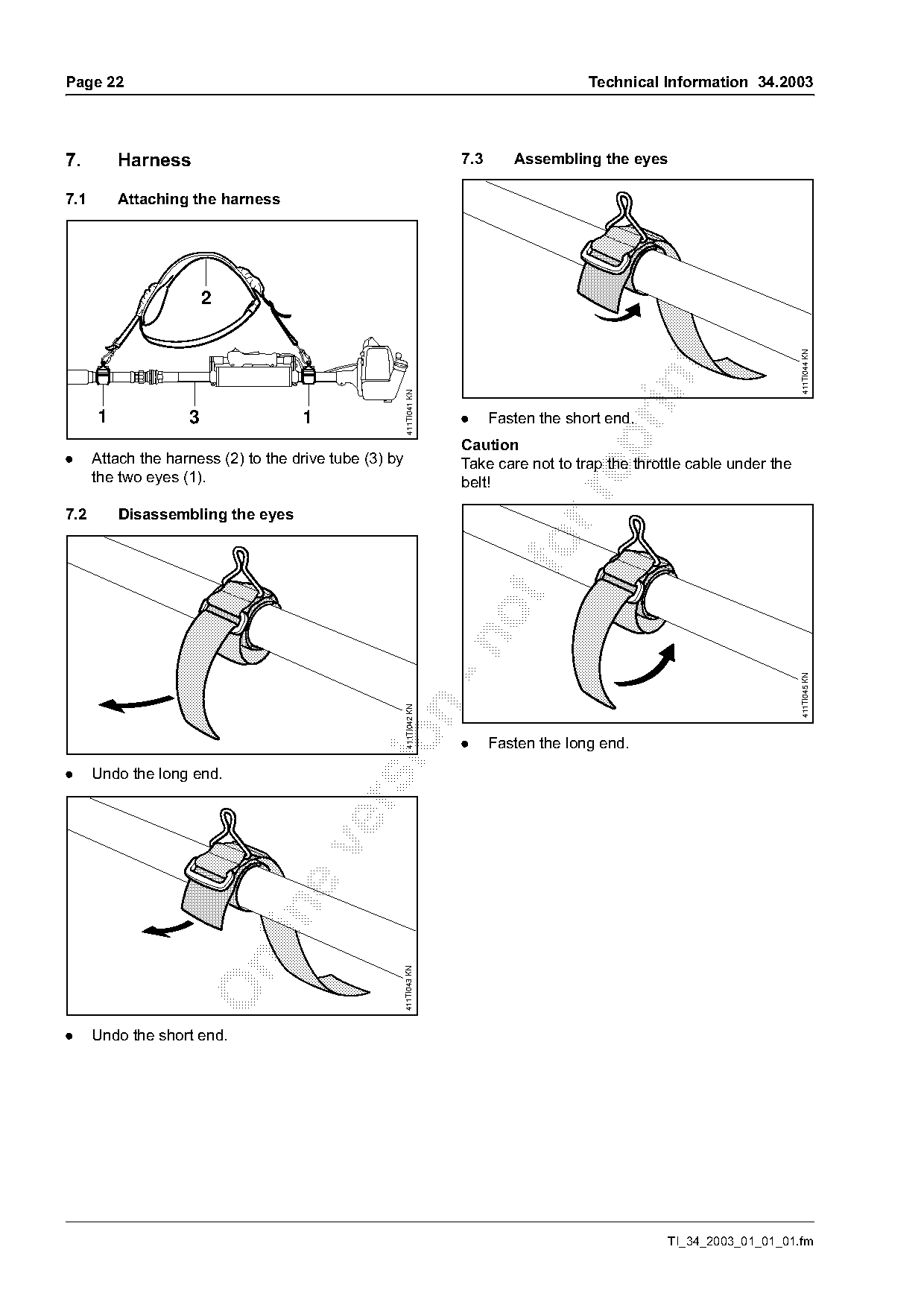
7.        Harness                                                      7.3      Assembling the eyes

7.1       Attaching the harness


                                                                                                                            411TI044 KN
                                                         411TI041 KN
      1             3                1                                 .     Fasten the short end.

                                                                       Caution
.     Attach the harness (2) to the drive tube (3) by                  Take care not to trap the throttle cable under the
      the two eyes (1).                                                belt!

7.2       Disassembling the eyes

                                                                                                                            411TI045 KN
                                                        411TI042 KN

                                                                       .     Fasten the long end.

.     Undo the long end.

                                                        411TI043 KN

.     Undo the short end.

                                                                                                      TI_34_2003_01_01_01.fm
Page 23 of 25
Text of page 23 — search, copy, screen readers
Technical Information 34.2003                                                                   Page 23

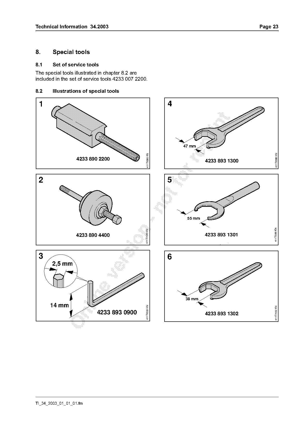
8.     Special tools

8.1     Set of service tools
The special tools illustrated in chapter 8.2 are
included in the set of service tools 4233 007 2200.

8.2     Illustrations of special tools

 1                                                                 4

                                                                       47 mm

                                                                                                      411TI088 KN
                                                    411TI085 KN

                   4233 890 2200

                                                                                4233 893 1300

 2                                                                 fo
                                                                   5

                                                                        55 mm

                                                                                                     411TI089 KN
                                            n     411TI100 KN

                   4233 890 4400                                                4233 893 1301

 3                                                                 6

       2,5 mm

                                                                       38 mm
      14 mm
                                                  411TI033 KN

                                                                                                     411TI102 KN

                           4233 893 0900

                                                                                4233 893 1302

TI_34_2003_01_01_01.fm
Page 24 of 25
Text of page 24 — search, copy, screen readers
Page 24                                                          Technical Information 34.2003

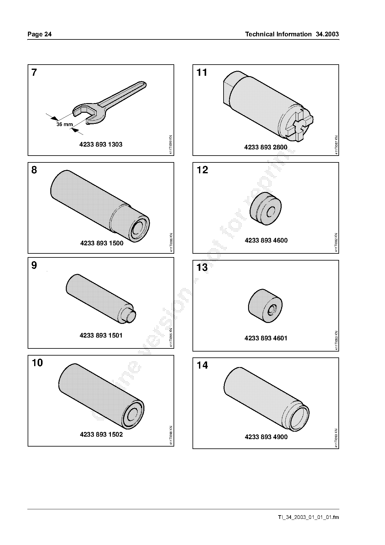
 7                                                     11

          36 mm

                                       411TI099 KN

                                                                                                411TI087 KN
                  4233 893 1303                                  4233 893 2800

 8                                                     12

                                         411TI086 KN

                                                                                               411TI082 KN
                  4233 893 1500                                  4233 893 4600

 9                                                     13
                                  sio   411TI095 KN

                                                                                                411TI083 KN

                  4233 893 1501                                  4233 893 4601

 10                                                    14

                                        411TI098 KN

                                                                                               411TI093 KN

                  4233 893 1502                                  4233 893 4900

                                                                           TI_34_2003_01_01_01.fm
Page 25 of 25
Text of page 25 — search, copy, screen readers
Technical Information 34.2003                                                             Page 25

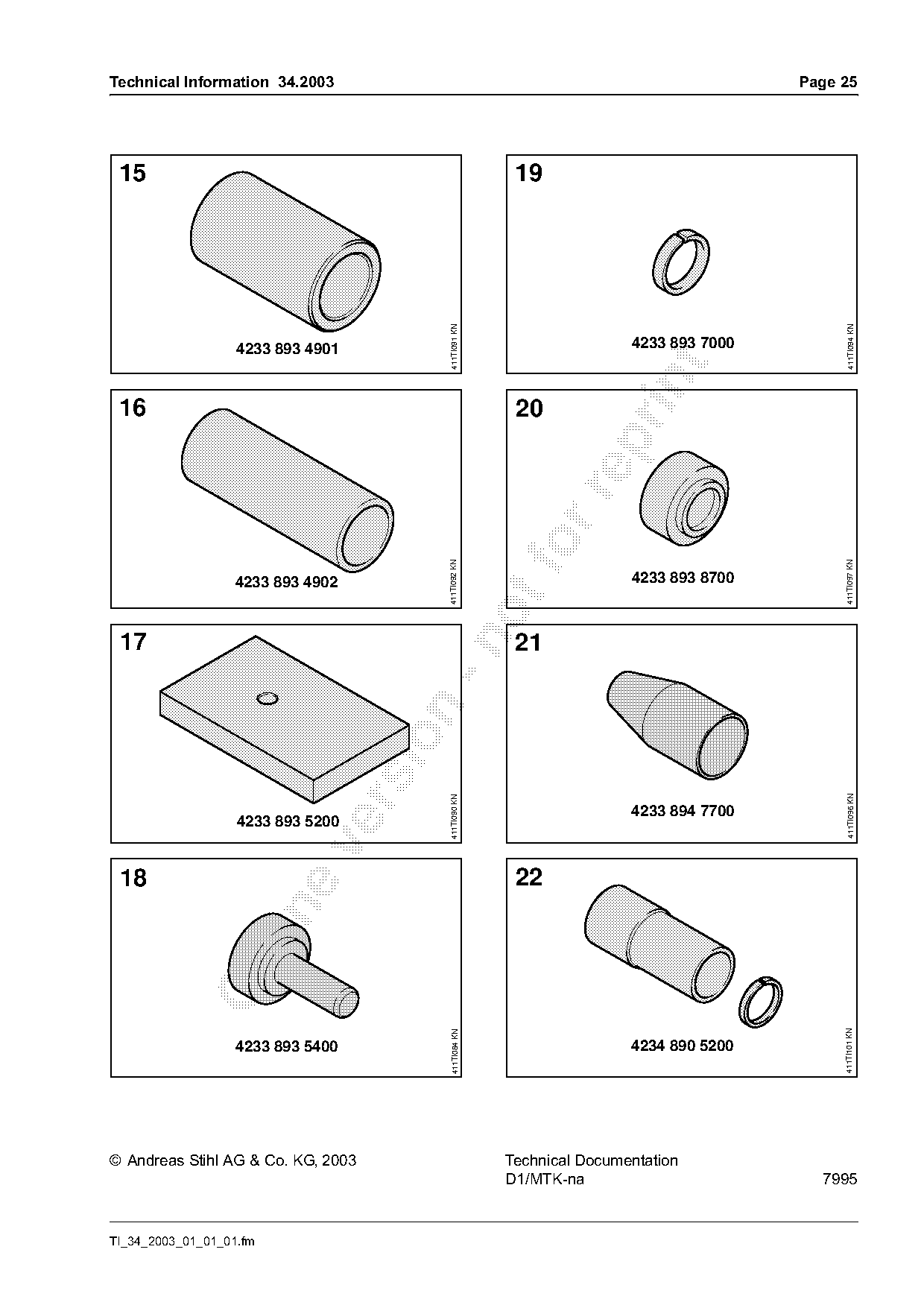
 15                                                        19

                                           411TI091 KN

                                                                                                411TI094 KN
                   4233 893 4901                                          4233 893 7000

 16                                                        20

                                          411TI092 KN

                                                                                               411TI097 KN
                   4233 893 4902                                          4233 893 8700

 17                                                        21

                                                                                                411TI096 KN
                                           411TI090 KN

                                                                          4233 894 7700
                   4233 893 5200

 18                                                        22

                                                                                               411TI101 KN
                                            411TI084 KN

                   4233 893 5400                                          4234 890 5200

© Andreas Stihl AG & Co. KG, 2003                         Technical Documentation
                                                          D1/MTK-na                         7995

TI_34_2003_01_01_01.fm
Most of these PDFs embed fonts with a shifted character map, so the text above was recovered rather than copied — read it as a faithful but imperfect transcription, and treat the page image above each block as the authority where the two disagree — the figures exist only there, because they are vector drawings that text extraction cannot keep.