Technical Information · issue 39 of 2003
Carburetor; Muffler and seal; Summary
IssueTI 39/2003
Engine family 1128
Part changes (1)
| Was | Becomes | What the bulletin says |
|---|---|---|
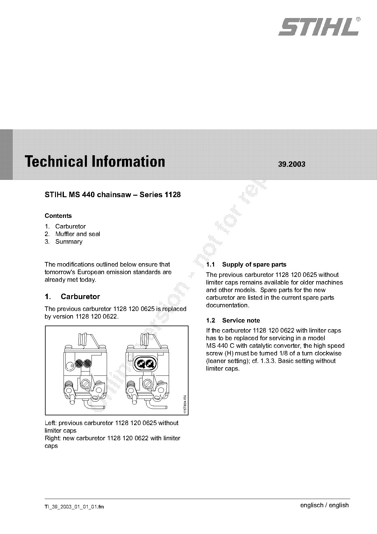
| 1128 120 0625 | 1128 120 0622 | The previous carburetor 1128 120 0625 is replaced by version 1128 120 0622. |
Full text
Page 1 of 5
Text of page 1 — search, copy, screen readers
STIH)

Technical Information

                                                                                            39.2003

  STIHL MS 440 chainsaw – Series 1128

  Contents
  1. Carburetor
  2. Muffler and seal
  3. Summary

  The modifications outlined below ensure that                     1.1   Supply of spare parts
  tomorrow's European emission standards are                       The previous carburetor 1128 120 0625 without
  already met today.                                               limiter caps remains available for older machines
                                                                   and other models. Spare parts for the new

  1.   Carburetor                                                  carburetor are listed in the current spare parts

                                                                   documentation.
  The previous carburetor 1128 120 0625 is replaced
  by version 1128 120 0622.
                                                                   1.2   Service note

                                                                   If the carburetor 1128 120 0622 with limiter caps
                                                                   has to be replaced for servicing in a model
                                                                   MS 440 C with catalytic converter, the high speed

                                                                   screw (H) must be turned 1/8 of a turn clockwise
                                                                   (leaner setting); cf. 1.3.3. Basic setting without
                                                                   limiter caps.

                                                     175TI004 KN

  Left: previous carburetor 1128 120 0625 without
  limiter caps
  Right: new carburetor 1128 120 0622 with limiter
  caps

  TI_39_2003_01_01_01.fm                                                                            englisch / english
Page 2 of 5
Text of page 2 — search, copy, screen readers
Page 2                                                                                  Technical Information 39.2003

1.3    Carburetor adjustment                                        1.3.2 Maintenance / repair

      H                                           L

                                                                                                                          175TI006 KN
                                                      178TI005 KN

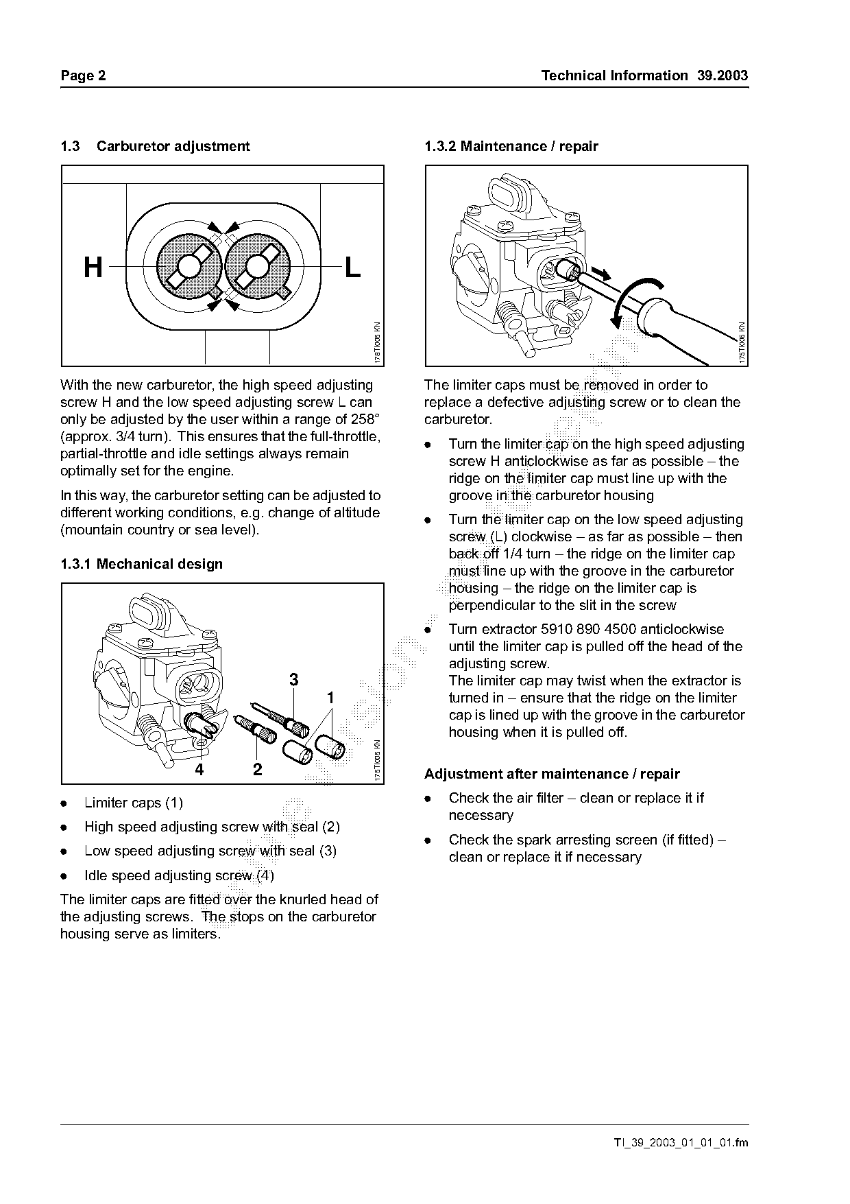
With the new carburetor, the high speed adjusting                   The limiter caps must be removed in order to
screw H and the low speed adjusting screw L can                     replace a defective adjusting screw or to clean the

only be adjusted by the user within a range of 258°                 carburetor.
(approx. 3/4 turn). This ensures that the full-throttle,
                                                                    .   Turn the limiter cap on the high speed adjusting
partial-throttle and idle settings always remain

                                                                        screw H anticlockwise as far as possible – the
optimally set for the engine.
                                                                        ridge on the limiter cap must line up with the
In this way, the carburetor setting can be adjusted to                  groove in the carburetor housing
different working conditions, e.g. change of altitude
(mountain country or sea level).
                                                                    .
                                                                        Turn the limiter cap on the low speed adjusting
                                                                        screw (L) clockwise – as far as possible – then
                                                                        back off 1/4 turn – the ridge on the limiter cap
1.3.1 Mechanical design                                                 must line up with the groove in the carburetor
                                                                        housing – the ridge on the limiter cap is

                                                                        perpendicular to the slit in the screw
                                                                    .   Turn extractor 5910 890 4500 anticlockwise
                                                                        until the limiter cap is pulled off the head of the

                                                                        adjusting screw.

                                       3                                The limiter cap may twist when the extractor is
                                              1                         turned in – ensure that the ridge on the limiter
                                                                        cap is lined up with the groove in the carburetor
                                                                        housing when it is pulled off.
                                                      175TI005 KN

                         4       2                                  Adjustment after maintenance / repair

.     Limiter caps (1)                                              .   Check the air filter – clean or replace it if
                                                                        necessary
.     High speed adjusting screw with seal (2)

                                                                    .   Check the spark arresting screen (if fitted) –
.     Low speed adjusting screw with seal (3)                           clean or replace it if necessary
.     Idle speed adjusting screw (4)

The limiter caps are fitted over the knurled head of
the adjusting screws. The stops on the carburetor
housing serve as limiters.

                                                                                                     TI_39_2003_01_01_01.fm
Page 3 of 5
Text of page 3 — search, copy, screen readers
Technical Information 39.2003                                                                                          Page 3

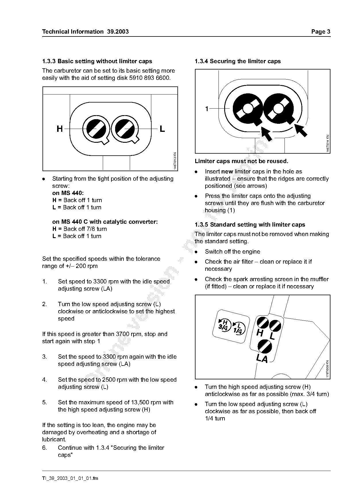
1.3.3 Basic setting without limiter caps                               1.3.4 Securing the limiter caps
The carburetor can be set to its basic setting more
easily with the aid of setting disk 5910 893 6600.


      H                                         L

                                                                                                                              146TI014 KN
                                                         146TI013 KN
                                                                       Limiter caps must not be reused.

                                                                       .   Insert new limiter caps in the hole as
.    Starting from the tight position of the adjusting                     illustrated – ensure that the ridges are correctly
     screw:                                                                positioned (see arrows)

     on MS 440:                                                        .   Press the limiter caps onto the adjusting
     H = Back off 1 turn                                                   screws until they are flush with the carburetor
     L = Back off 1 turn

     on MS 440 C with catalytic converter:
                                                                           housing (1)

                                                                       1.3.5 Standard setting with limiter caps
     H = Back off 7/8 turn
     L = Back off 1 turn                                               The limiter caps must not be removed when making
                                                                       the standard setting.

                                                                       .   Switch off the engine
Set the specified speeds within the tolerance
                                                                       .   Check the air filter – clean or replace it if
range of +/– 200 rpm                                                       necessary

1.     Set speed to 3300 rpm with the idle speed                       .   Check the spark arresting screen in the muffler

       adjusting screw (LA)                                                (if fitted) – clean or replace it if necessary

2.     Turn the low speed adjusting screw (L)

       clockwise or anticlockwise to set the highest
       speed
                                                                                  H

If this speed is greater than 3700 rpm, stop and                                                H L
start again with step 1

3.     Set the speed to 3300 rpm again with the idle                                            LA
                                                                                                                             178TI008 KN

       speed adjusting screw (LA)

4.     Set the speed to 2500 rpm with the low speed
       adjusting screw (L)                                             .   Turn the high speed adjusting screw (H)
                                                                           anticlockwise as far as possible (max. 3/4 turn)
5.     Set the maximum speed of 13,500 rpm with                        .   Turn the low speed adjusting screw (L)
       the high speed adjusting screw (H)                                  clockwise as far as possible, then back off
                                                                           1/4 turn
If the setting is too lean, the engine may be
damaged by overheating and a shortage of
lubricant.
6.     Continue with 1.3.4 "Securing the limiter
       caps"

TI_39_2003_01_01_01.fm
Page 4 of 5
Text of page 4 — search, copy, screen readers
Page 4                                                                     Technical Information 39.2003

Idle speed adjustment                                    2.   Muffler and seal
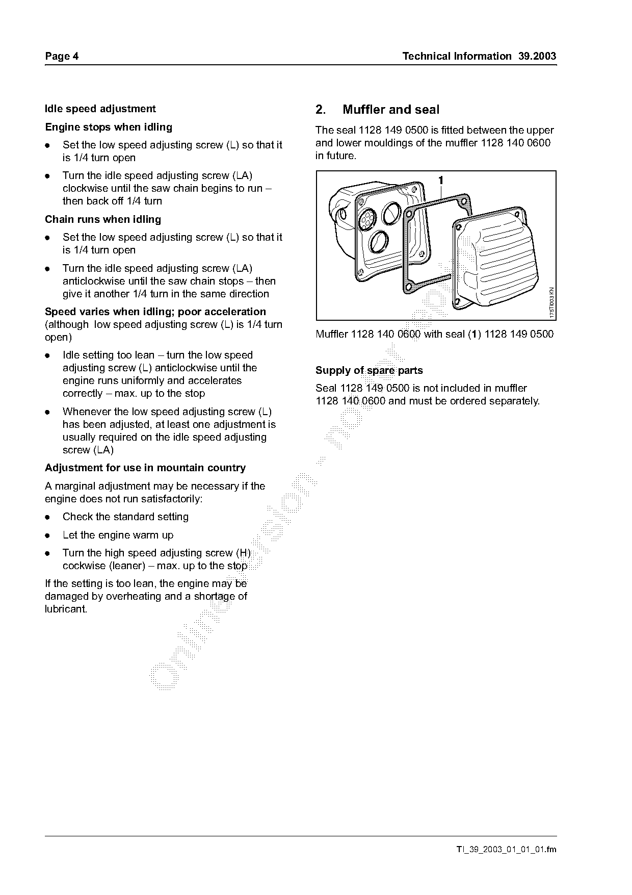
Engine stops when idling                                 The seal 1128 149 0500 is fitted between the upper
.   Set the low speed adjusting screw (L) so that it     and lower mouldings of the muffler 1128 140 0600
    is 1/4 turn open                                     in future.
.   Turn the idle speed adjusting screw (LA)                                      1
    clockwise until the saw chain begins to run –
    then back off 1/4 turn
Chain runs when idling
.   Set the low speed adjusting screw (L) so that it
    is 1/4 turn open

.   Turn the idle speed adjusting screw (LA)
    anticlockwise until the saw chain stops – then

                                                                                                          175TI003 KN
    give it another 1/4 turn in the same direction

Speed varies when idling; poor acceleration
(although low speed adjusting screw (L) is 1/4 turn
open)                                                    Muffler 1128 140 0600 with seal (1) 1128 149 0500

.   Idle setting too lean – turn the low speed
    adjusting screw (L) anticlockwise until the          Supply of spare parts
    engine runs uniformly and accelerates
    correctly – max. up to the stop
                                                         Seal 1128 149 0500 is not included in muffler
                                                         1128 140 0600 and must be ordered separately.
.   Whenever the low speed adjusting screw (L)
    has been adjusted, at least one adjustment is
    usually required on the idle speed adjusting

    screw (LA)
Adjustment for use in mountain country
A marginal adjustment may be necessary if the

engine does not run satisfactorily:

.   Check the standard setting
.   Let the engine warm up

.   Turn the high speed adjusting screw (H)
    cockwise (leaner) – max. up to the stop

If the setting is too lean, the engine may be
damaged by overheating and a shortage of
lubricant.

                                                                                      TI_39_2003_01_01_01.fm
Page 5 of 5
Text of page 5 — search, copy, screen readers
Technical Information 39.2003                                                               Page 5

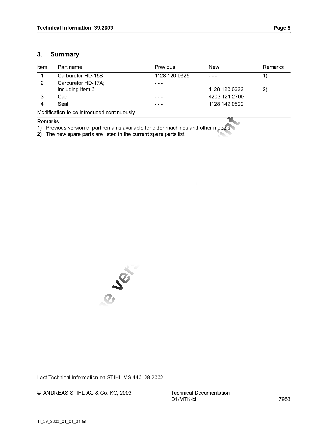
3.     Summary
Item     Part name                               Previous              New             Remarks
 1       Carburetor HD-15B                       1128 120 0625         ---             1)
 2       Carburetor HD-17A;                      ---
         including Item 3                                              1128 120 0622   2)
 3       Cap                                     ---                   4203 121 2700
 4       Seal                                    ---                   1128 149 0500
Modification to be introduced continuously
Remarks

1) Previous version of part remains available for older machines and other models

2) The new spare parts are listed in the current spare parts list

Last Technical Information on STIHL MS 440: 28.2002

© ANDREAS STIHL AG & Co. KG, 2003                       Technical Documentation
                                                        D1/MTK-bl                            7953

TI_39_2003_01_01_01.fm
Most of these PDFs embed fonts with a shifted character map, so the text above was recovered rather than copied — read it as a faithful but imperfect transcription, and treat the page image above each block as the authority where the two disagree — the figures exist only there, because they are vector drawings that text extraction cannot keep.