Technical Information · issue 40 of 2003
Carburetor; Muffler and gasket; Summary
Model MS 460 Chainsaw – Series 1128
IssueTI 40/2003
Engine family 1128
Full text
Page 1 of 5
Text of page 1 — search, copy, screen readers
STIH)

Technical Information

                                                                                              40.2003

  Model MS 460 Chainsaw – Series 1128

  Contents
  1. Carburetor
  2. Muffler and gasket
  3. Summary

  The engineering changes described below ensure                   1.1   Parts availability
  compliance with future emission standards in                     The previous carburetor 1128 120 0624 without
  Europe.                                                          limiter caps remains available as a spare for older

                                                                   machines and other models. Spare parts for the new

  1.   Carburetor                                                  carburetor are included in the latest parts list.
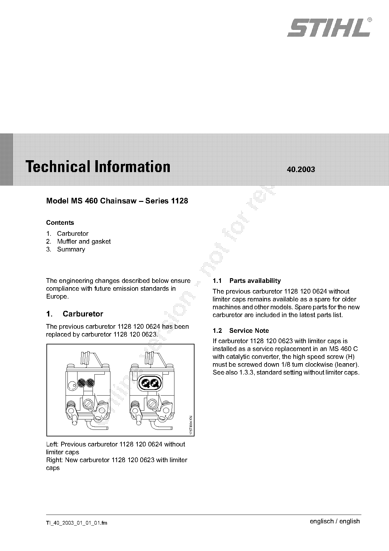
  The previous carburetor 1128 120 0624 has been
                                                                   1.2   Service Note
  replaced by carburetor 1128 120 0623.

                                                                   If carburetor 1128 120 0623 with limiter caps is
                                                                   installed as a service replacement in an MS 460 C
                                                                   with catalytic converter, the high speed screw (H)

                                                                   must be screwed down 1/8 turn clockwise (leaner).
                                                                   See also 1.3.3, standard setting without limiter caps.

                                                     175TI004 KN

  Left: Previous carburetor 1128 120 0624 without
  limiter caps
  Right: New carburetor 1128 120 0623 with limiter
  caps

  TI_40_2003_01_01_01.fm                                                                              englisch / english
Page 2 of 5
Text of page 2 — search, copy, screen readers
Page 2                                                                                      Technical Information 40.2003

1.3    Adjusting the Carburetor                                          1.3.2 Servicing / Repairs

      H                                            L

                                                                                                                              175TI006 KN
                                                           178TI005 KN

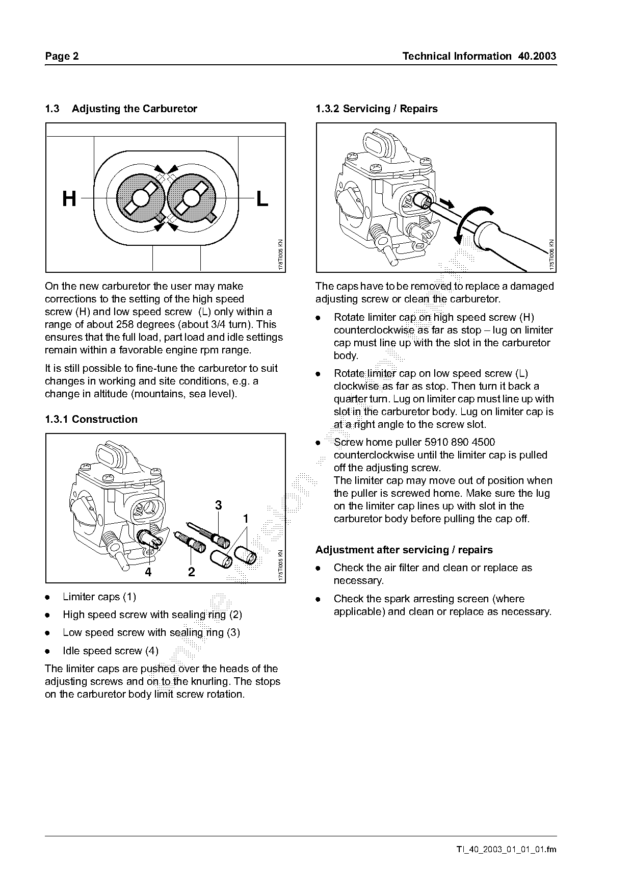
On the new carburetor the user may make                                  The caps have to be removed to replace a damaged
corrections to the setting of the high speed                             adjusting screw or clean the carburetor.

screw (H) and low speed screw (L) only within a
                                                                         .   Rotate limiter cap on high speed screw (H)
range of about 258 degrees (about 3/4 turn). This
                                                                             counterclockwise as far as stop – lug on limiter
ensures that the full load, part load and idle settings

                                                                             cap must line up with the slot in the carburetor
remain within a favorable engine rpm range.
                                                                             body.
It is still possible to fine-tune the carburetor to suit
changes in working and site conditions, e.g. a
change in altitude (mountains, sea level).
                                                                         .       fo
                                                                             Rotate limiter cap on low speed screw (L)
                                                                             clockwise as far as stop. Then turn it back a
                                                                             quarter turn. Lug on limiter cap must line up with
                                                                             slot in the carburetor body. Lug on limiter cap is
1.3.1 Construction                                                           at a right angle to the screw slot.

                                                                         .   Screw home puller 5910 890 4500
                                                                             counterclockwise until the limiter cap is pulled
                                                                             off the adjusting screw.
                                                                             The limiter cap may move out of position when

                                                                             the puller is screwed home. Make sure the lug

                                        3                                    on the limiter cap lines up with slot in the
                                               1                             carburetor body before pulling the cap off.

                                                                         Adjustment after servicing / repairs
                                                           175TI005 KN

                         4        2                                      .   Check the air filter and clean or replace as

                                                                             necessary.
.     Limiter caps (1)                                                   .   Check the spark arresting screen (where
.     High speed screw with sealing ring (2)                                 applicable) and clean or replace as necessary.

.     Low speed screw with sealing ring (3)
.     Idle speed screw (4)

The limiter caps are pushed over the heads of the
adjusting screws and on to the knurling. The stops
on the carburetor body limit screw rotation.

                                                                                                        TI_40_2003_01_01_01.fm
Page 3 of 5
Text of page 3 — search, copy, screen readers
Technical Information 40.2003                                                                                      Page 3

1.3.3 Standard setting without limiter caps                         1.3.4 Securing limiter caps
Setting disc 5910 893 6600 simplifies the
adjustment.


      H                                         L

                                                                                                                          146TI014 KN
                                                      146TI013 KN
                                                                    Do not re-install used caps

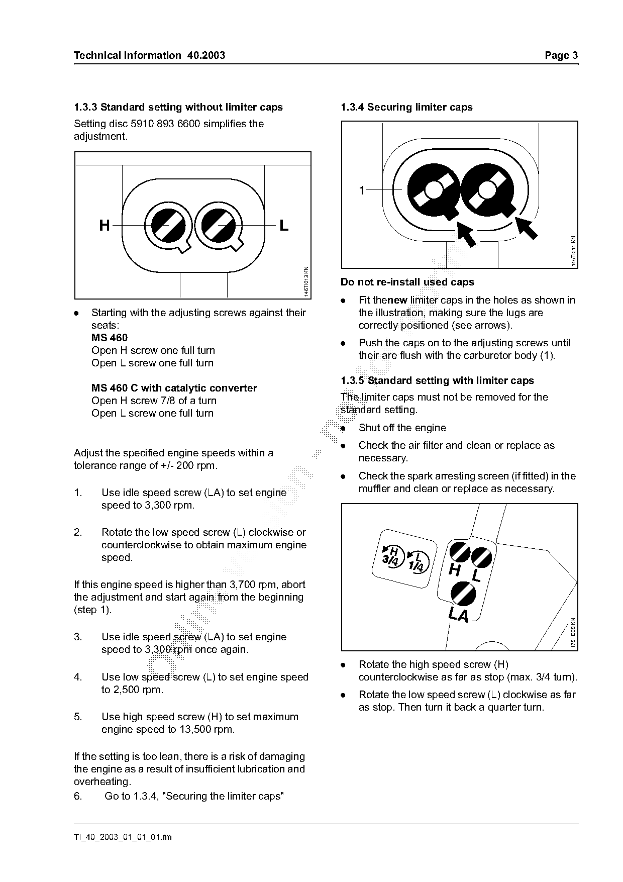
                                                                    .   Fit thenew limiter caps in the holes as shown in
.    Starting with the adjusting screws against their                   the illustration, making sure the lugs are
     seats:                                                             correctly positioned (see arrows).

     MS 460                                                         .   Push the caps on to the adjusting screws until
     Open H screw one full turn                                         their are flush with the carburetor body (1).
     Open L screw one full turn

     MS 460 C with catalytic converter
                                                                    1.3.5 Standard setting with limiter caps
     Open H screw 7/8 of a turn                                     The limiter caps must not be removed for the
     Open L screw one full turn                                     standard setting.
                                                                    .   Shut off the engine

                                                                    .   Check the air filter and clean or replace as
Adjust the specified engine speeds within a
                                                                        necessary.
tolerance range of +/- 200 rpm.
                                                                    .   Check the spark arresting screen (if fitted) in the

1.     Use idle speed screw (LA) to set engine                          muffler and clean or replace as necessary.

       speed to 3,300 rpm.

2.     Rotate the low speed screw (L) clockwise or

       counterclockwise to obtain maximum engine
                                                                               H
       speed.                                                                        L
                                                                                              H L

If this engine speed is higher than 3,700 rpm, abort
the adjustment and start again from the beginning
(step 1).                                                                                     LA

                                                                                                                         178TI008 KN

3.     Use idle speed screw (LA) to set engine
       speed to 3,300 rpm once again.

                                                                    .   Rotate the high speed screw (H)
4.     Use low speed screw (L) to set engine speed                      counterclockwise as far as stop (max. 3/4 turn).
       to 2,500 rpm.
                                                                    .   Rotate the low speed screw (L) clockwise as far
                                                                        as stop. Then turn it back a quarter turn.
5.     Use high speed screw (H) to set maximum
       engine speed to 13,500 rpm.

If the setting is too lean, there is a risk of damaging
the engine as a result of insufficient lubrication and
overheating.
6.      Go to 1.3.4, "Securing the limiter caps"

TI_40_2003_01_01_01.fm
Page 4 of 5
Text of page 4 — search, copy, screen readers
Page 4                                                                         Technical Information 40.2003

Adjusting idle                                            2.   Muffler and gasket
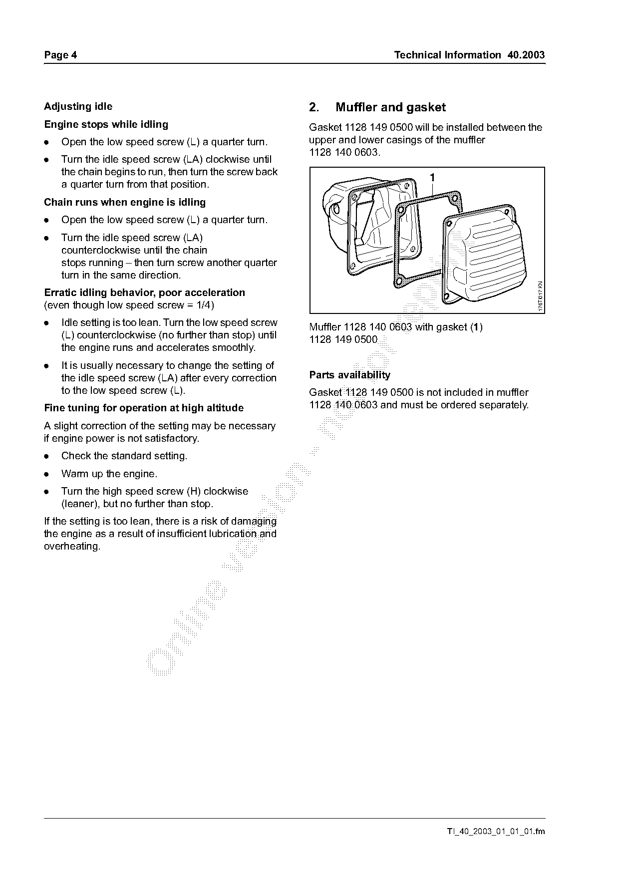
Engine stops while idling                                 Gasket 1128 149 0500 will be installed between the
.   Open the low speed screw (L) a quarter turn.          upper and lower casings of the muffler
                                                          1128 140 0603.
.   Turn the idle speed screw (LA) clockwise until
    the chain begins to run, then turn the screw back
                                                                                     1
    a quarter turn from that position.
Chain runs when engine is idling
.   Open the low speed screw (L) a quarter turn.
.   Turn the idle speed screw (LA)

    counterclockwise until the chain

    stops running – then turn screw another quarter
    turn in the same direction.

                                                                                                             176TI017 KN
Erratic idling behavior, poor acceleration

(even though low speed screw = 1/4)
.   Idle setting is too lean. Turn the low speed screw    Muffler 1128 140 0603 with gasket (1)

    (L) counterclockwise (no further than stop) until     1128 149 0500
    the engine runs and accelerates smoothly.
.   It is usually necessary to change the setting of
    the idle speed screw (LA) after every correction
                                                          Parts availability
    to the low speed screw (L).                           Gasket 1128 149 0500 is not included in muffler
Fine tuning for operation at high altitude                1128 140 0603 and must be ordered separately.
A slight correction of the setting may be necessary

if engine power is not satisfactory.
.   Check the standard setting.
.   Warm up the engine.

.   Turn the high speed screw (H) clockwise

    (leaner), but no further than stop.
If the setting is too lean, there is a risk of damaging
the engine as a result of insufficient lubrication and

overheating.

                                                                                         TI_40_2003_01_01_01.fm
Page 5 of 5
Text of page 5 — search, copy, screen readers
Technical Information 40.2003                                                               Page 5

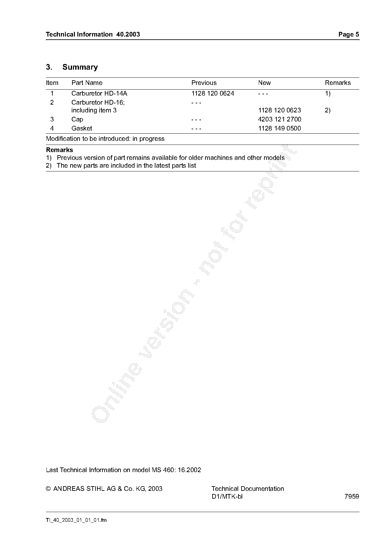
3.     Summary
Item     Part Name                               Previous              New             Remarks
 1       Carburetor HD-14A                       1128 120 0624         ---             1)
 2       Carburetor HD-16;                       ---
         including item 3                                              1128 120 0623   2)
 3       Cap                                     ---                   4203 121 2700
 4       Gasket                                  ---                   1128 149 0500
Modification to be introduced: in progress
Remarks

1) Previous version of part remains available for older machines and other models

2) The new parts are included in the latest parts list

Last Technical Information on model MS 460: 16.2002

© ANDREAS STIHL AG & Co. KG, 2003                       Technical Documentation
                                                        D1/MTK-bl                            7959

TI_40_2003_01_01_01.fm
Most of these PDFs embed fonts with a shifted character map, so the text above was recovered rather than copied — read it as a faithful but imperfect transcription, and treat the page image above each block as the authority where the two disagree — the figures exist only there, because they are vector drawings that text extraction cannot keep.