Technical Information · issue 41 of 2003
Tank vent, filter housing and fuel tank; Handlebar with rotating handle holder; Carburetor; Spark plug
IssueTI 41/2003
Part changes (2)
| Was | Becomes | What the bulletin says |
|---|---|---|
| 0000 350 5800 | 0000 350 5804 | 1 Tank vent The previous tank vent 0000 350 5800 is replaced by version 0000 350 5804. |
| 4137 790 1701 | 4128 790 1701 | At the same time, the previous handlebar 4137 790 1701 will be replaced by version 4128 790 1701 (mowing handle). |
Full text
Page 1 of 6
Text of page 1 — search, copy, screen readers
STIH)

Technical Information

                                                                                    41.2003

  STIHL FS 110 brushcutter                                – Series 4180

  STIHL KM 110 R CombiEngine                              – Series 4180

  Contents
  1.    Tank vent, filter housing and fuel tank
  2.    Handlebar with rotating handle holder-FS 110
  3.    Carburetor
  4.    Spark plug

  1.       Tank vent, filter housing and

           fuel tank

  The tank will be vented via the clean-air side of the
  air filter. The tank vent and filter housing are
  connected by a hose for this purpose.

  1.1      Tank vent
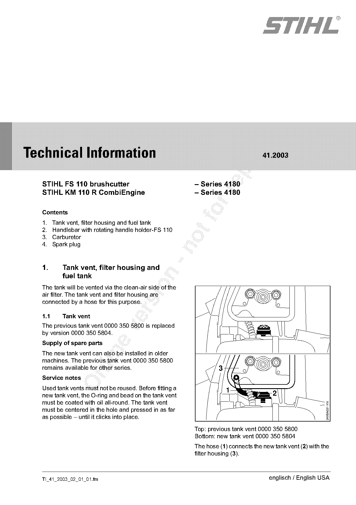
  The previous tank vent 0000 350 5800 is replaced

  by version 0000 350 5804.
  Supply of spare parts

  The new tank vent can also be installed in older
  machines. The previous tank vent 0000 350 5800
  remains available for other series.                              3

  Service notes
  Used tank vents must not be reused. Before fitting a                 1
  new tank vent, the O-ring and bead on the tank vent                                   2
  must be coated with oil all-round. The tank vent
                                                                                                            249BA031 KN

  must be centered in the hole and pressed in as far
  as possible – until it clicks into place.

                                                          Top: previous tank vent 0000 350 5800
                                                          Bottom: new tank vent 0000 350 5804
                                                          The hose (1) connects the new tank vent (2) with the
                                                          filter housing (3).

  TI_41_2003_02_01_01.fm                                                              englisch / English USA
Page 2 of 6
Text of page 2 — search, copy, screen readers
Page 2                                                                               Technical Information 41.2003

1.2       Fuel tank                                              1.3     Filter housing
The previous fuel tank 4180 350 0410 is replaced                 The previous filter housing 4180 140 2800 is
by the new version 4180 350 0412.                                replaced by version 4180 140 2802.
The new fuel tank already includes the new tank
vent 0000 350 5804 and hose 4119 141 8600.
Supply of spare parts
The previous fuel tank only remains available while
stocks last.

      1                   2

                                                                                                                      249TI033 KN
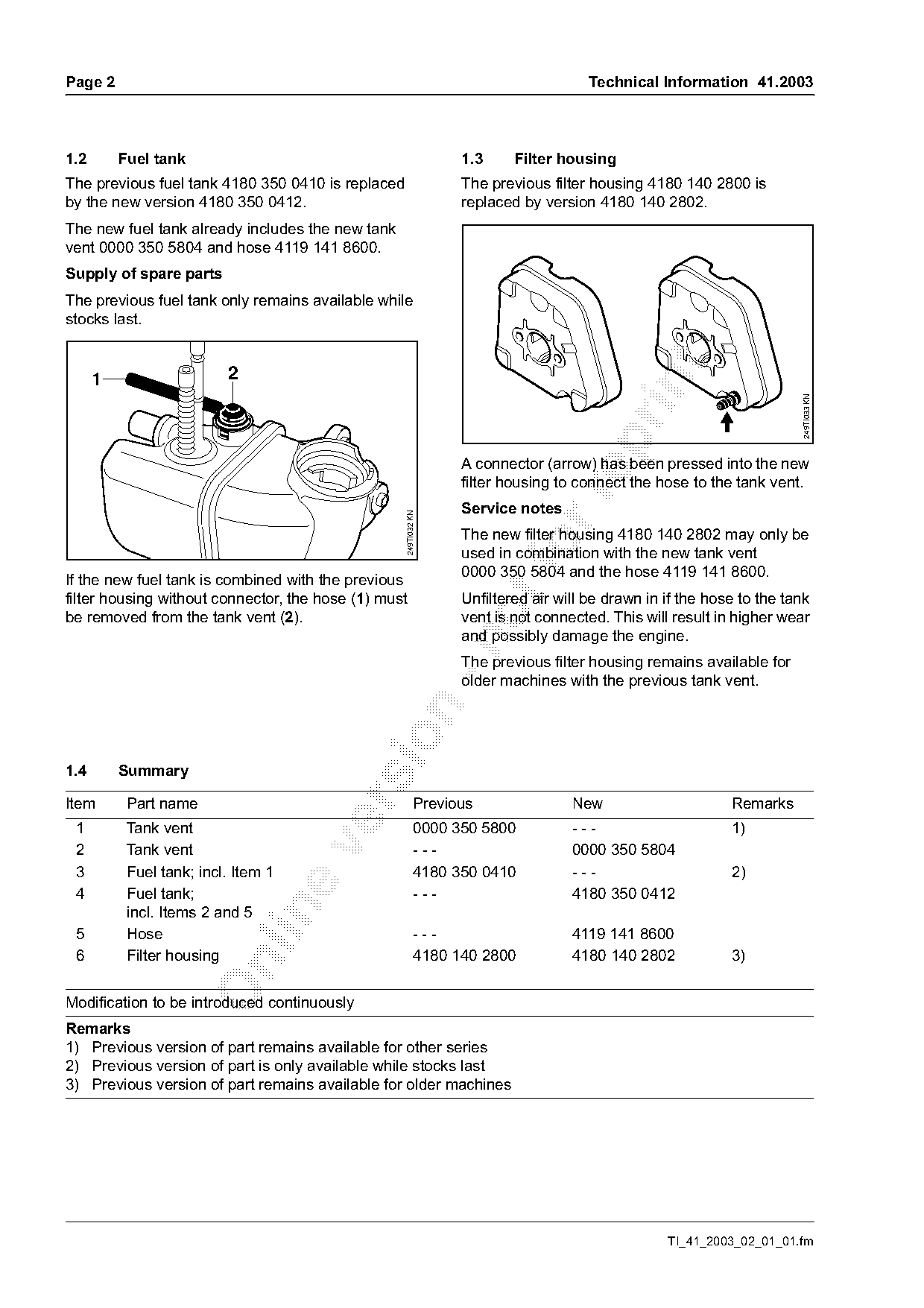
                                                                 A connector (arrow) has been pressed into the new
                                                                 filter housing to connect the hose to the tank vent.

                                                                 Service notes
                                                   249TI032 KN

                                                                 The new filter housing 4180 140 2802 may only be
                                                                 used in combination with the new tank vent
                                                                 0000 350 5804 and the hose 4119 141 8600.
If the new fuel tank is combined with the previous
filter housing without connector, the hose (1) must              Unfiltered air will be drawn in if the hose to the tank
be removed from the tank vent (2).                               vent is not connected. This will result in higher wear
                                                                 and possibly damage the engine.

                                                                 The previous filter housing remains available for
                                                                 older machines with the previous tank vent.

1.4       Summary

Item       Part name                                      Previous                New                      Remarks

 1         Tank vent                                       0000 350 5800          ---                      1)

 2         Tank vent                                       ---                    0000 350 5804
 3         Fuel tank; incl. Item 1                         4180 350 0410          ---                      2)
 4         Fuel tank;                                      ---                    4180 350 0412

           incl. Items 2 and 5
 5         Hose                                            ---                    4119 141 8600
 6         Filter housing                                  4180 140 2800          4180 140 2802            3)

Modification to be introduced continuously
Remarks
1) Previous version of part remains available for other series
2) Previous version of part is only available while stocks last
3) Previous version of part remains available for older machines

                                                                                                 TI_41_2003_02_01_01.fm
Page 3 of 6
Text of page 3 — search, copy, screen readers
Technical Information 41.2003                                                                                    Page 3

2.       Handlebar with rotating handle                           2.2       Swivelling the handlebar
         holder-FS 110
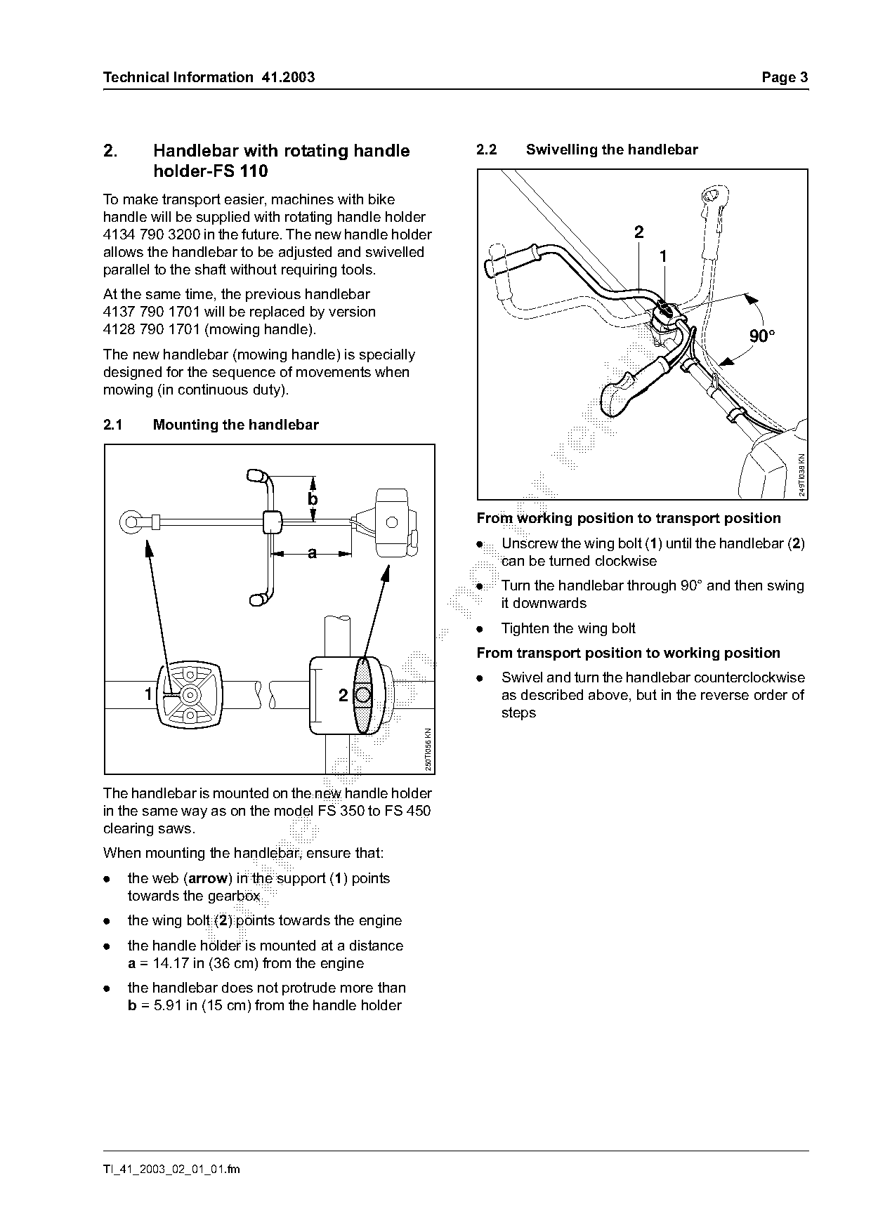
To make transport easier, machines with bike
handle will be supplied with rotating handle holder
4134 790 3200 in the future. The new handle holder                                           2
allows the handlebar to be adjusted and swivelled                                                1
parallel to the shaft without requiring tools.
At the same time, the previous handlebar
4137 790 1701 will be replaced by version
4128 790 1701 (mowing handle).
                                                                                                               90°

The new handlebar (mowing handle) is specially

designed for the sequence of movements when
mowing (in continuous duty).

2.1      Mounting the handlebar

                                                                                                                       249TI038 KN
                                  b

                                                                  .
                                                                  From working position to transport position
                                                                        Unscrew the wing bolt (1) until the handlebar (2)
                                  a                                     can be turned clockwise
                                                                  .     Turn the handlebar through 90° and then swing
                                                                        it downwards

                                                                  .     Tighten the wing bolt
                                                                  From transport position to working position

                                                                  .     Swivel and turn the handlebar counterclockwise
        1                                                               as described above, but in the reverse order of

                                       2
                                                                        steps
                                                    250TI056 KN

The handlebar is mounted on the new handle holder

in the same way as on the model FS 350 to FS 450
clearing saws.
When mounting the handlebar, ensure that:

.     the web (arrow) in the support (1) points
      towards the gearbox

.     the wing bolt (2) points towards the engine
.     the handle holder is mounted at a distance
      a = 14.17 in (36 cm) from the engine
.     the handlebar does not protrude more than
      b = 5.91 in (15 cm) from the handle holder

TI_41_2003_02_01_01.fm
Page 4 of 6
Text of page 4 — search, copy, screen readers
Page 4                                                                     Technical Information 41.2003

                                                                  1
                             15
                                                                  2
                                                                  3
              14


              11                                                                    4
                                                                                    5

                                  12                                                6
                                                                                    7

              13
                                                                  8

                                                                                                            249TI037 KN
                                                                  9
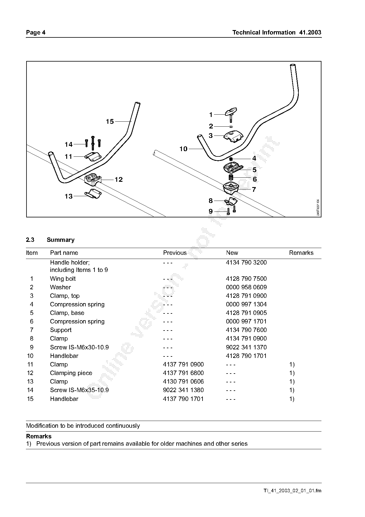
2.3      Summary

Item     Part name                                Previous               New                     Remarks

         Handle holder;                           ---                    4134 790 3200
         including Items 1 to 9
 1       Wing bolt                                ---                    4128 790 7500

 2       Washer                                   ---                    0000 958 0609

 3       Clamp, top                               ---                    4128 791 0900
 4       Compression spring                       ---                    0000 997 1304
 5       Clamp, base                              ---                    4128 791 0905

 6       Compression spring                       ---                    0000 997 1701
 7       Support                                  ---                    4134 790 7600

 8       Clamp                                    ---                    4134 791 0900
 9       Screw IS-M6x30-10.9                      ---                    9022 341 1370
10       Handlebar                                ---                    4128 790 1701

11       Clamp                                    4137 791 0900          ---                     1)
12       Clamping piece                           4137 791 6800          ---                     1)

13       Clamp                                    4130 791 0606          ---                     1)
14       Screw IS-M6x35-10.9                      9022 341 1380          ---                     1)
15       Handlebar                                4137 790 1701          ---                     1)

Modification to be introduced continuously
Remarks
1) Previous version of part remains available for older machines and other series

                                                                                        TI_41_2003_02_01_01.fm
Page 5 of 6
Text of page 5 — search, copy, screen readers
Technical Information 41.2003                                                                                    Page 5

3.     Carburetor                                                  Service notes

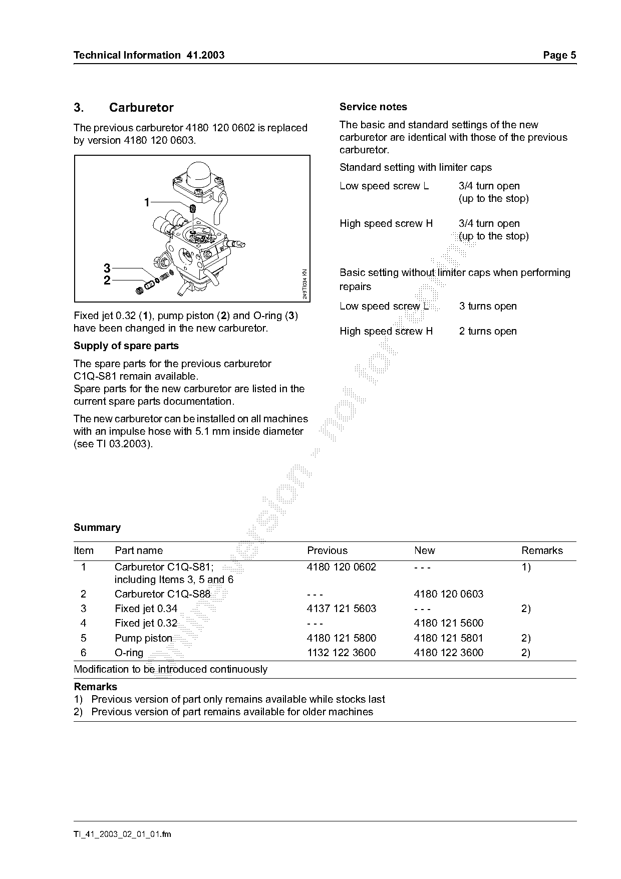
The previous carburetor 4180 120 0602 is replaced                  The basic and standard settings of the new
by version 4180 120 0603.                                          carburetor are identical with those of the previous
                                                                   carburetor.
                                                                   Standard setting with limiter caps
                                                                   Low speed screw L         3/4 turn open
                 1                                                                           (up to the stop)

                                                                   High speed screw H        3/4 turn open
                                                                                             (up to the stop)

       3                                                           Basic setting without limiter caps when performing

                                                     249TI034 KN
       2                                                           repairs

                                                                   Low speed screw L         3 turns open
Fixed jet 0.32 (1), pump piston (2) and O-ring (3)
have been changed in the new carburetor.                           High speed screw H        2 turns open

Supply of spare parts
The spare parts for the previous carburetor
C1Q-S81 remain available.
Spare parts for the new carburetor are listed in the
current spare parts documentation.

The new carburetor can be installed on all machines
with an impulse hose with 5.1 mm inside diameter

(see TI 03.2003).

Summary

Item       Part name                                         Previous              New                      Remarks
 1         Carburetor C1Q-S81;                               4180 120 0602         ---                      1)

           including Items 3, 5 and 6
 2         Carburetor C1Q-S88                                ---                   4180 120 0603
 3         Fixed jet 0.34                                    4137 121 5603         ---                      2)

 4         Fixed jet 0.32                                    ---                   4180 121 5600
 5         Pump piston                                       4180 121 5800         4180 121 5801            2)

 6         O-ring                                            1132 122 3600         4180 122 3600            2)
Modification to be introduced continuously
Remarks
1) Previous version of part only remains available while stocks last
2) Previous version of part remains available for older machines

TI_41_2003_02_01_01.fm
Page 6 of 6
Text of page 6 — search, copy, screen readers
Page 6                                                                    Technical Information 41.2003

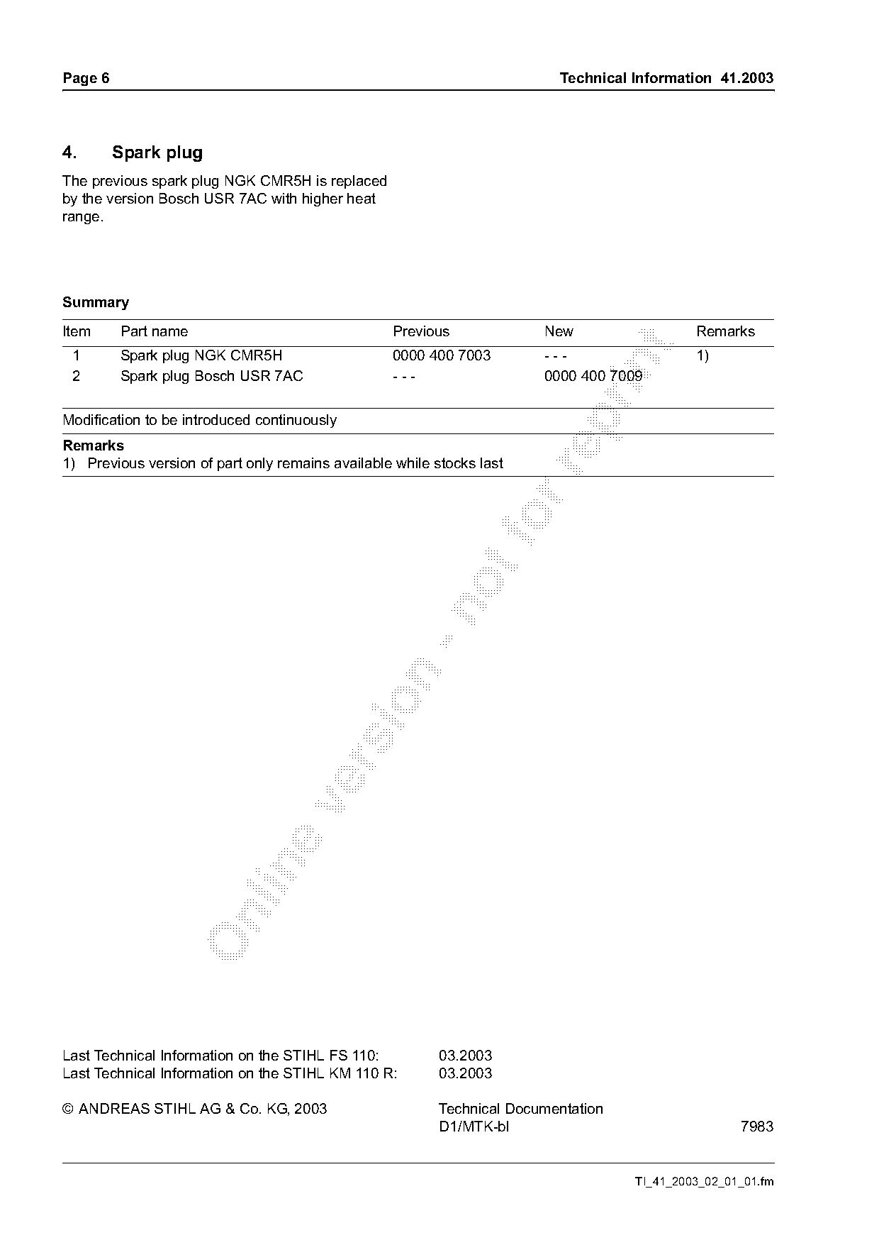
4.       Spark plug
The previous spark plug NGK CMR5H is replaced
by the version Bosch USR 7AC with higher heat
range.

Summary

Item     Part name                                Previous              New                  Remarks

 1       Spark plug NGK CMR5H                     0000 400 7003         ---                  1)

 2       Spark plug Bosch USR 7AC                 ---                   0000 400 7009

Modification to be introduced continuously

Remarks
1) Previous version of part only remains available while stocks last

Last Technical Information on the STIHL FS 110:           03.2003
Last Technical Information on the STIHL KM 110 R:         03.2003

© ANDREAS STIHL AG & Co. KG, 2003                         Technical Documentation
                                                          D1/MTK-bl                                 7983

                                                                                    TI_41_2003_02_01_01.fm
Most of these PDFs embed fonts with a shifted character map, so the text above was recovered rather than copied — read it as a faithful but imperfect transcription, and treat the page image above each block as the authority where the two disagree — the figures exist only there, because they are vector drawings that text extraction cannot keep.