Technical Information · issue 45 of 2003
STIHL MultiSystem; MultiEngine MM 55; Noise and vibration values; Gear position; MultiTools; Special accessories; Service accessories; Spare parts; Repairs
IssueTI 45/2003
Part changes (4)
| Was | Becomes | What the bulletin says |
|---|---|---|
| 4601 011 3900 | 4601 011 3903 | Version 4601 011 3900 is replaced by the new version 4601 011 3903. |
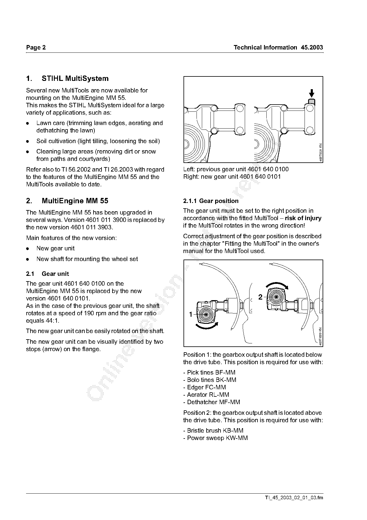
| 4601 640 0100 | 4601 640 0101 | The gear unit 4601 640 0100 on the MultiEngine MM 55 is replaced by the new version 4601 640 0101. |
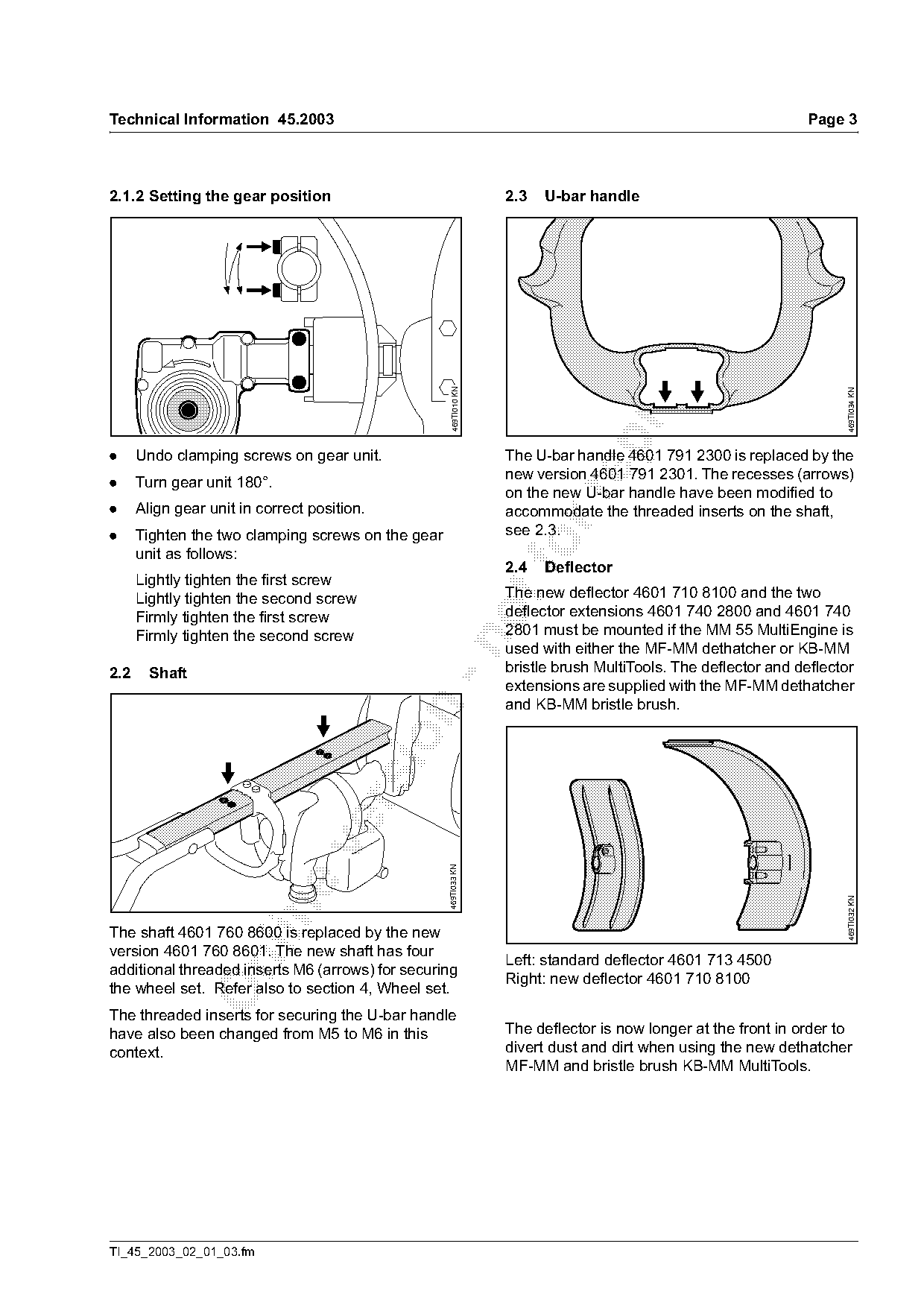
| 4601 791 2300 | 4601 791 2301 | The U-bar handle 4601 791 2300 is replaced by the new version 4601 791 2301. |
| 4601 760 8600 | 4601 760 8601 | The shaft 4601 760 8600 is replaced by the new version 4601 760 8601. |
Full text
Page 1 of 10
Text of page 1 — search, copy, screen readers
STIH)

Technical Information                                       45.2003

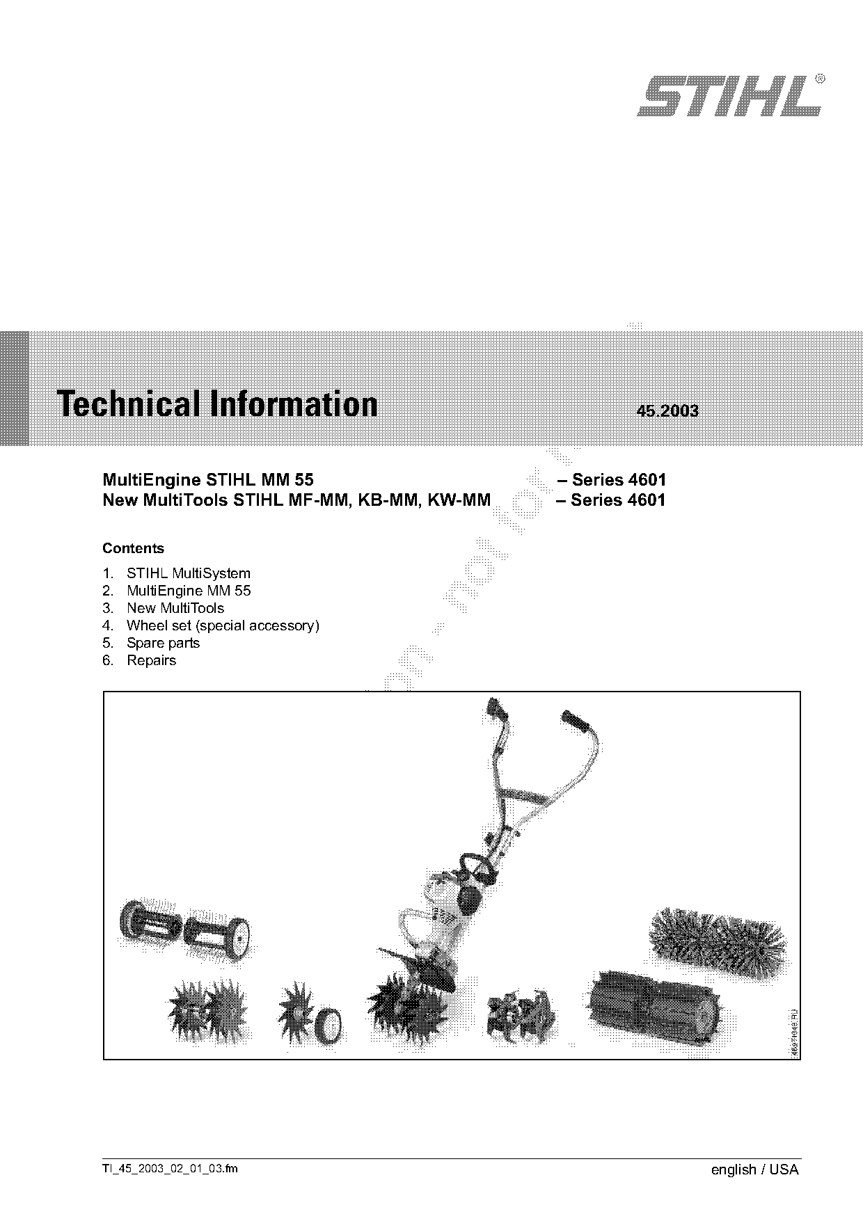
  MultiEngine STIHL MM 55                          – Series 4601
  New MultiTools STIHL MF-MM, KB-MM, KW-MM         – Series 4601
  Contents
  1.   STIHL MultiSystem
  2.   MultiEngine MM 55

  3.   New MultiTools
  4.   Wheel set (special accessory)
  5.   Spare parts
  6.   Repairs

  TI_45_2003_02_01_03.fm                                              english / USA
Page 2 of 10
Text of page 2 — search, copy, screen readers
Page 2                                                                              Technical Information 45.2003

1.      STIHL MultiSystem
Several new MultiTools are now available for
mounting on the MultiEngine MM 55.
This makes the STIHL MultiSystem ideal for a large
variety of applications, such as:
.     Lawn care (trimming lawn edges, aerating and
      dethatching the lawn)
.     Soil cultivation (light tilling, loosening the soil)

                                                                                                                       469TI031 KN
.     Cleaning large areas (removing dirt or snow

      from paths and courtyards)
Refer also to TI 56.2002 and TI 26.2003 with regard              Left: previous gear unit 4601 640 0100

to the features of the MultiEngine MM 55 and the                 Right: new gear unit 4601 640 0101
MultiTools available to date.

2.      MultiEngine MM 55                                        2.1.1 Gear position
The MultiEngine MM 55 has been upgraded in                       The gear unit must be set to the right position in
several ways. Version 4601 011 3900 is replaced by
the new version 4601 011 3903.
                                                                 accordance with the fitted MultiTool – risk of injury
                                                                 if the MultiTool rotates in the wrong direction!

Main features of the new version:                                Correct adjustment of the gear position is described
                                                                 in the chapter "Fitting the MultiTool" in the owner's
.     New gear unit                                              manual for the MultiTool used.

.     New shaft for mounting the wheel set

2.1     Gear unit

The gear unit 4601 640 0100 on the
MultiEngine MM 55 is replaced by the new

version 4601 640 0101.                                                                        2
As in the case of the previous gear unit, the shaft
rotates at a speed of 190 rpm and the gear ratio                   1

equals 44:1.                                                                                                          469TI009 KN

The new gear unit can be easily rotated on the shaft.

The new gear unit can be visually identified by two
stops (arrow) on the flange.
                                                                 Position 1: the gearbox output shaft is located below
                                                                 the drive tube. This position is required for use with:

                                                                 - Pick tines BF-MM
                                                                 - Bolo tines BK-MM

                                                                 - Edger FC-MM
                                                                 - Aerator RL-MM
                                                                 - Dethatcher MF-MM
                                                                 Position 2: the gearbox output shaft is located above
                                                                 the drive tube. This position is required for use with:
                                                                 - Bristle brush KB-MM
                                                                 - Power sweep KW-MM

                                                                                                  TI_45_2003_02_01_03.fm
Page 3 of 10
Text of page 3 — search, copy, screen readers
Technical Information 45.2003                                                                                    Page 3

2.1.2 Setting the gear position                                     2.3   U-bar handle

                                                      469TI010 KN

                                                                                                                        469TI034 KN
.     Undo clamping screws on gear unit.                            The U-bar handle 4601 791 2300 is replaced by the
                                                                    new version 4601 791 2301. The recesses (arrows)
.     Turn gear unit 180°.
                                                                    on the new U-bar handle have been modified to

.     Align gear unit in correct position.                          accommodate the threaded inserts on the shaft,
.     Tighten the two clamping screws on the gear                   see 2.3.
      unit as follows:                                               fo
                                                                    2.4   Deflector
      Lightly tighten the first screw
      Lightly tighten the second screw                              The new deflector 4601 710 8100 and the two
      Firmly tighten the first screw                                deflector extensions 4601 740 2800 and 4601 740
      Firmly tighten the second screw                               2801 must be mounted if the MM 55 MultiEngine is

                                                                    used with either the MF-MM dethatcher or KB-MM
2.2     Shaft                                                       bristle brush MultiTools. The deflector and deflector
                                                                    extensions are supplied with the MF-MM dethatcher
                                                                    and KB-MM bristle brush.

                                                    469TI033 KN

                                                                                                                        469TI032 KN

The shaft 4601 760 8600 is replaced by the new
version 4601 760 8601. The new shaft has four
                                                                    Left: standard deflector 4601 713 4500

additional threaded inserts M6 (arrows) for securing
                                                                    Right: new deflector 4601 710 8100
the wheel set. Refer also to section 4, Wheel set.
The threaded inserts for securing the U-bar handle
have also been changed from M5 to M6 in this                        The deflector is now longer at the front in order to
context.                                                            divert dust and dirt when using the new dethatcher
                                                                    MF-MM and bristle brush KB-MM MultiTools.

TI_45_2003_02_01_03.fm
Page 4 of 10
Text of page 4 — search, copy, screen readers
Page 4                                                                                  Technical Information 45.2003


                                                                                                 7              6

              1                      1

                                                                                                                          469TI043 KN
                                                     469TI024KN
                                                                                                 7

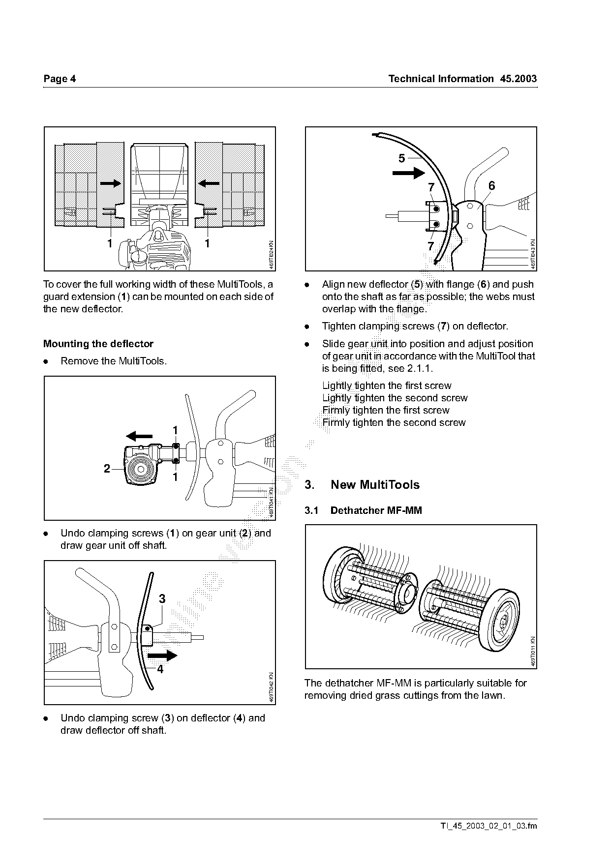
To cover the full working width of these MultiTools, a             .     Align new deflector (5) with flange (6) and push

guard extension (1) can be mounted on each side of                       onto the shaft as far as possible; the webs must
the new deflector.                                                       overlap with the flange.
                                                                   .     Tighten clamping screws (7) on deflector.

Mounting the deflector                                             .     Slide gear unit into position and adjust position
                                                                         of gear unit in accordance with the MultiTool that
.   Remove the MultiTools.                                                   fo
                                                                         is being fitted, see 2.1.1.
                                                                         Lightly tighten the first screw
                                                                         Lightly tighten the second screw
                                                                         Firmly tighten the first screw
                                                                         Firmly tighten the second screw


              2
                               1
                                                                   3.      New MultiTools
                                             sio     469TI041 KN

                                                                   3.1     Dethatcher MF-MM

.   Undo clamping screws (1) on gear unit (2) and
    draw gear unit off shaft.


                                                                                                                          469TI011 KN

                          4
                                                     469TI042 KN

                                                                   The dethatcher MF-MM is particularly suitable for
                                                                   removing dried grass cuttings from the lawn.

.   Undo clamping screw (3) on deflector (4) and
    draw deflector off shaft.

                                                                                                     TI_45_2003_02_01_03.fm
Page 5 of 10
Text of page 5 — search, copy, screen readers
Technical Information 45.2003                                                                                            Page 5

                                                                     Risk of damage if the parts rotate in the wrong
                                                                     direction. The spring tines may break.
                                                                     .       Turn the left-hand dethatcher (1) on the shaft
                                                                             until it can be slipped into position.
                                                                     .       Insert the spring clip (2) in the hole in the shaft
                                                                             so that it engages.
                                                                     .       Mount the right-hand dethatcher in the same
                                                                             way.

                                                                     Mounting and dismounting the guard extension

                                                                         fo             1                      1

                                                                                                                                469TI024KN
                                                       469TI012 KN

                                                                     The right and left-hand guard extensions are

                                                                     different.
                                                                     .       Fit the right-hand extension on the guard so that
3.1.1 Scope of supply                                                        the tab (1) engages.

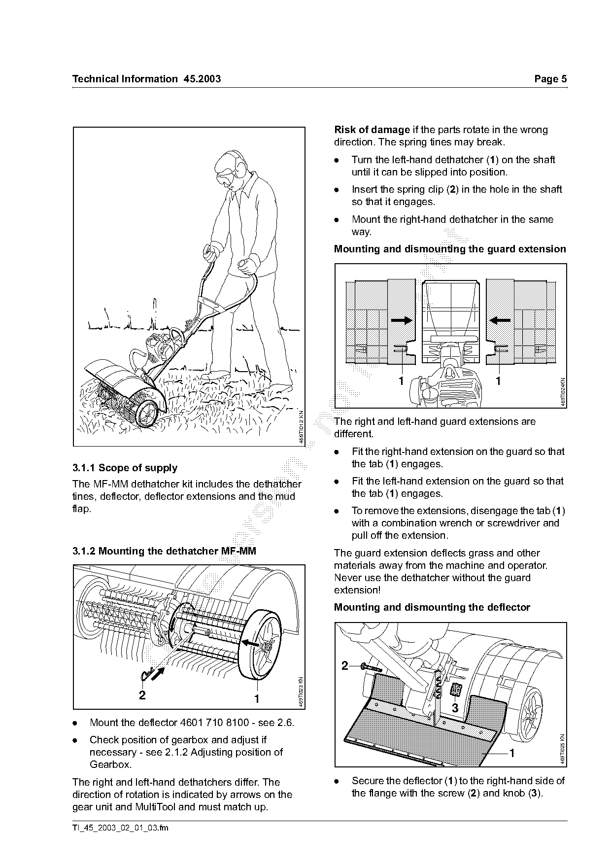
The MF-MM dethatcher kit includes the dethatcher                     .       Fit the left-hand extension on the guard so that

tines, deflector, deflector extensions and the mud                           the tab (1) engages.
flap.                                                                .       To remove the extensions, disengage the tab (1)
                                                                             with a combination wrench or screwdriver and

                                                                             pull off the extension.
3.1.2 Mounting the dethatcher MF-MM                                  The guard extension deflects grass and other

                                                                     materials away from the machine and operator.
                                                                     Never use the dethatcher without the guard
                                                                     extension!

                                                                     Mounting and dismounting the deflector

                                                                         2
                                                      469TI023 KN

               2                          1
                                                                                                     3
.   Mount the deflector 4601 710 8100 - see 2.6.
.   Check position of gearbox and adjust if
                                                                                                                               469TI025 KN

    necessary - see 2.1.2 Adjusting position of                                                                    1
    Gearbox.
The right and left-hand dethatchers differ. The                      .       Secure the deflector (1) to the right-hand side of
direction of rotation is indicated by arrows on the                          the flange with the screw (2) and knob (3).
gear unit and MultiTool and must match up.
TI_45_2003_02_01_03.fm
Page 6 of 10
Text of page 6 — search, copy, screen readers
Page 6                                                                                 Technical Information 45.2003

.   Adjust the deflector to the required depth so that             3.2    Bristle brush KB-MM
    it overlaps with the guard.
.   Tighten the knob (3).
The deflector guides grass and other materials
away from the machine and operator. Never use the
dethatcher without the deflector!
Cleaning the dethatcher
During use, grass or roots may become firmly

wrapped around the tool mount and implement.

To clean the implement:

                                                                                                                        469TI015 KN
.   Dismount the dethatcher.

.   Pull the outer spring clip (on the wheel) from the
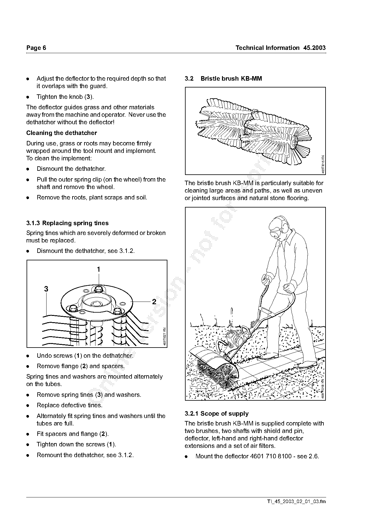
                                                                   The bristle brush KB-MM is particularly suitable for
    shaft and remove the wheel.
                                                                   cleaning large areas and paths, as well as uneven
.   Remove the roots, plant scraps and soil.                       or jointed surfaces and natural stone flooring.

3.1.3 Replacing spring tines                                                fo
Spring tines which are severely deformed or broken
must be replaced.
.   Dismount the dethatcher, see 3.1.2.


                                                2
                                                     469TI027 KN

.   Undo screws (1) on the dethatcher.

.   Remove flange (2) and spacers.
Spring tines and washers are mounted alternately
                                                                                                                        469TI018 KN

on the tubes.

.   Remove spring tines (3) and washers.
.   Replace defective tines.
.   Alternately fit spring tines and washers until the             3.2.1 Scope of supply
    tubes are full.                                                The bristle brush KB-MM is supplied complete with
.   Fit spacers and flange (2).                                    two brushes, two shafts with shield and pin,
                                                                   deflector, left-hand and right-hand deflector
.   Tighten down the screws (1).                                   extensions and a set of air filters.
.   Remount the dethatcher, see 3.1.2.                             .     Mount the deflector 4601 710 8100 - see 2.6.

                                                                                                  TI_45_2003_02_01_03.fm
Page 7 of 10
Text of page 7 — search, copy, screen readers
Technical Information 45.2003                                                                                      Page 7

3.2.2 Mounting the bristle brush KB-MM                                 Mounting and dismounting the guard extension
.   Check position of gearbox and adjust if                            The guard extension is mounted in the same way as
    necessary - see 2.1.2 Adjusting Position of                        for the dethatcher MF-MM, see 3.1.2.
    Gearbox.
                                                                       The guard extension deflects material away from
                                                                       the machine and operator.
                                                                       Never use the bristle brush without guard extension!

                                                                       3.3   Power sweep KW-MM

    1                           2                        469TI028 KN

.   Firmly slide the shield (1) as far as possible onto
    the shaft (2).

                                                                                                                         469TI017 KN
                                           4
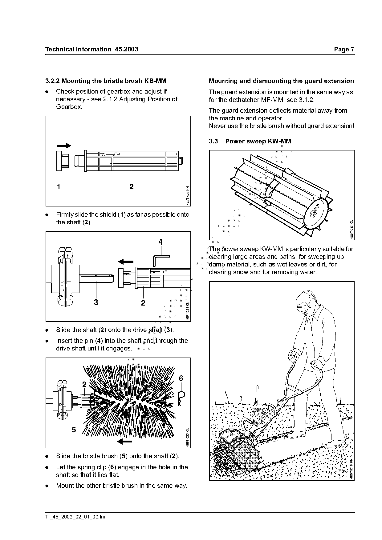
                                                                       The power sweep KW-MM is particularly suitable for
                                                                       clearing large areas and paths, for sweeping up
                                                                       damp material, such as wet leaves or dirt, for

                                                                       clearing snow and for removing water.

                  3                 2
                                                        469TI029 KN

.   Slide the shaft (2) onto the drive shaft (3).

.   Insert the pin (4) into the shaft and through the
    drive shaft until it engages.

                                                    6
             2

         5
                                                        469TI030 KN

.   Slide the bristle brush (5) onto the shaft (2).
                                                                                                                         469TI018 KN

.   Let the spring clip (6) engage in the hole in the
    shaft so that it lies flat.
.   Mount the other bristle brush in the same way.

TI_45_2003_02_01_03.fm
Page 8 of 10
Text of page 8 — search, copy, screen readers
Page 8                                                                               Technical Information 45.2003

3.3.1 Scope of supply                                             3.3.3 Deflector, deflector extensions
The power sweep KW-MM is supplied complete with                   The deflector 4601 710 8100 and the two deflector
two sweeper drums, two shafts with shield and pin,                extensions 4601 740 2800 and 4601 740 2801 may
and a set of air filters.                                         be used with the PowerSweep. They divert material
                                                                  and debris away from the machine and operator.
3.3.2 Mounting the power sweep KW-MM
                                                                  .   Mount the deflector 4601 710 8100 - see 2.6.
The power sweep is mounted in the same way as
                                                                  .   The guard extension is mounted in the same
the bristle brush KB-MM, see 3.2.2.
                                                                      way as for the dethatcher MF-MM, see 3.1.2.

3.4   Specifications

MultiTool                              Working width                  Diameter                 Weight
Dethatcher MF-MM                       21.7 in. (550 mm)              -                        12.3 lbs. (5.6 kg)
Bristle brush KB-MM                    23.6 in. (600 mm)              9.8 in. (250 mm)          9.0 lbs. (4.1 kg)

Power sweep KW-MM                      23.6 in. (600 mm)              9.8 in. (250 mm)         10.6 lbs. (4.8 kg)

4.    Wheel set (special accessory)
                                                                  To simplify installation of the wheels, turn the power
                                                                  tool over so that it rests on the handles.
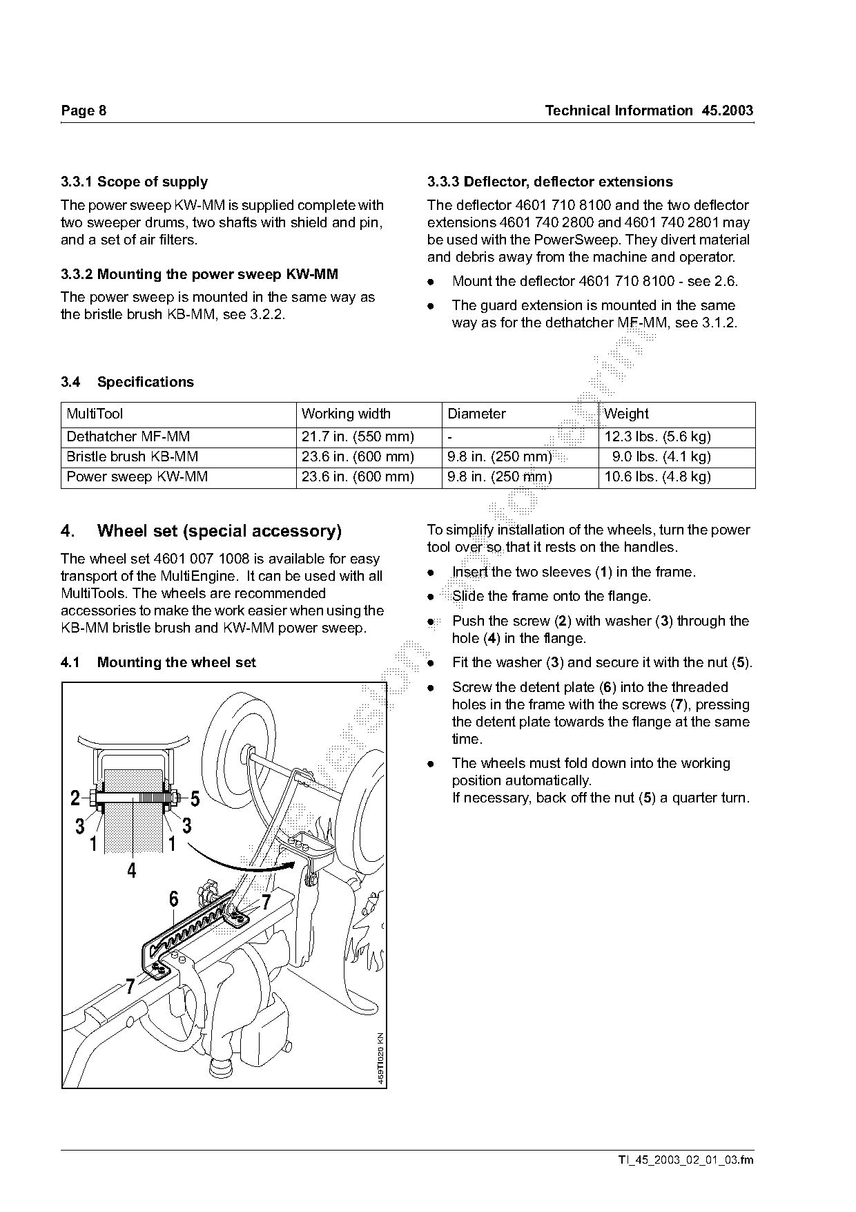
The wheel set 4601 007 1008 is available for easy
transport of the MultiEngine. It can be used with all             .   Insert the two sleeves (1) in the frame.
MultiTools. The wheels are recommended

                                                                  .   Slide the frame onto the flange.
accessories to make the work easier when using the
                                                                  .   Push the screw (2) with washer (3) through the
KB-MM bristle brush and KW-MM power sweep.
                                                                      hole (4) in the flange.

4.1   Mounting the wheel set                                      .   Fit the washer (3) and secure it with the nut (5).

                                                                  .   Screw the detent plate (6) into the threaded
                                                                      holes in the frame with the screws (7), pressing
                                                                      the detent plate towards the flange at the same
                                                                      time.

                                                                  .   The wheels must fold down into the working
                                                                      position automatically.

 2                    5                                               If necessary, back off the nut (5) a quarter turn.

 3                   3
      1          1


                 6              7

            7
                                                    469TI020 KN

                                                                                                  TI_45_2003_02_01_03.fm
Page 9 of 10
Text of page 9 — search, copy, screen readers
Technical Information 45.2003                                                                                   Page 9

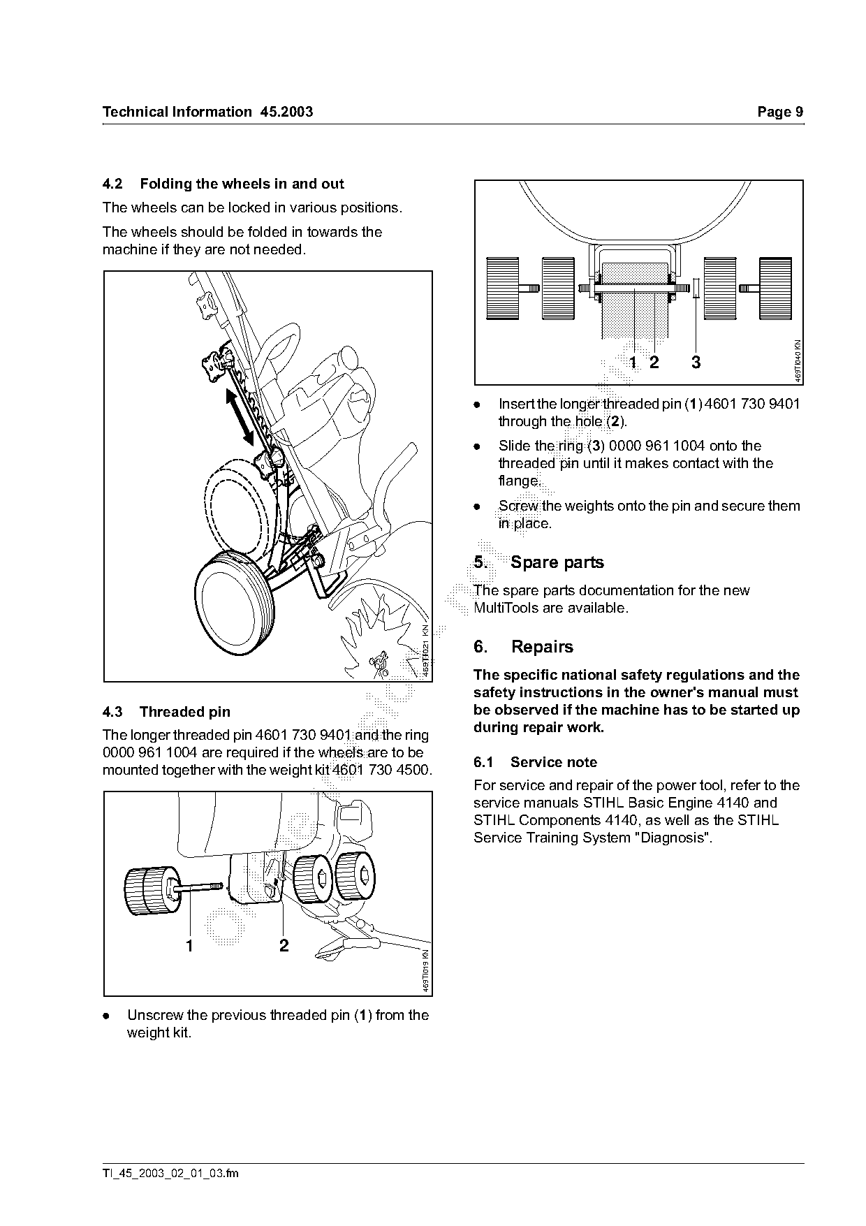
4.2    Folding the wheels in and out
The wheels can be locked in various positions.
The wheels should be folded in towards the
machine if they are not needed.

                                                                                                                      469TI040 KN
                                                                                           1 2       3

                                                                 .     Insert the longer threaded pin (1) 4601 730 9401

                                                                       through the hole (2).
                                                                 .     Slide the ring (3) 0000 961 1004 onto the
                                                                       threaded pin until it makes contact with the

                                                                       flange.
                                                                 .     Screw the weights onto the pin and secure them
                                                                     foin place.

                                                                 5.     Spare parts

                                                                 The spare parts documentation for the new

                                                                 MultiTools are available.
                                                   469TI021 KN

                                                                 6.     Repairs

                                                                 The specific national safety regulations and the
                                                                 safety instructions in the owner's manual must

4.3    Threaded pin                                              be observed if the machine has to be started up
                                                                 during repair work.
The longer threaded pin 4601 730 9401 and the ring
0000 961 1004 are required if the wheels are to be

                                                                 6.1    Service note
mounted together with the weight kit 4601 730 4500.
                                                                 For service and repair of the power tool, refer to the

                                                                 service manuals STIHL Basic Engine 4140 and
                                                                 STIHL Components 4140, as well as the STIHL
                                                                 Service Training System "Diagnosis".

              1              2
                                                   469TI019 KN

.     Unscrew the previous threaded pin (1) from the
      weight kit.

TI_45_2003_02_01_03.fm
Page 10 of 10
Text of page 10 — search, copy, screen readers
Page 10                                                                   Technical Information 45.2003

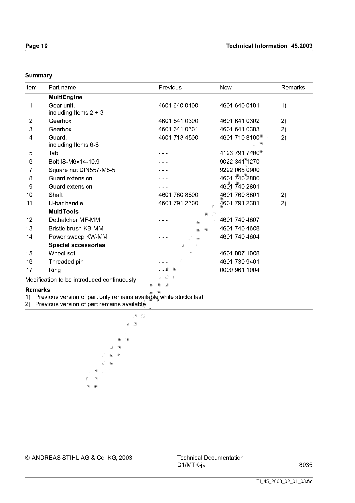
Summary

Item      Part name                               Previous              New                  Remarks
          MultiEngine
 1        Gear unit,                              4601 640 0100         4601 640 0101        1)
          including Items 2 + 3
 2        Gearbox                                 4601 641 0300         4601 641 0302        2)
 3        Gearbox                                 4601 641 0301         4601 641 0303        2)
 4        Guard,                                  4601 713 4500         4601 710 8100        2)

          including Items 6-8

 5        Tab                                     ---                   4123 791 7400
 6        Bolt IS-M6x14-10.9                      ---                   9022 341 1270
 7        Square nut DIN557-M6-5                  ---                   9222 068 0900

 8        Guard extension                         ---                   4601 740 2800
 9        Guard extension                         ---                   4601 740 2801

10        Shaft                                   4601 760 8600         4601 760 8601        2)
11        U-bar handle                            4601 791 2300         4601 791 2301        2)

12
          MultiTools
          Dethatcher MF-MM                        ---
                                                                  fo    4601 740 4607
13        Bristle brush KB-MM                     ---                   4601 740 4608
14        Power sweep KW-MM                       ---                   4601 740 4604
          Special accessories

15        Wheel set                               ---                   4601 007 1008
16        Threaded pin                            ---                   4601 730 9401
17        Ring                                    ---                   0000 961 1004

Modification to be introduced continuously

Remarks
1) Previous version of part only remains available while stocks last
2) Previous version of part remains available

© ANDREAS STIHL AG & Co. KG, 2003                         Technical Documentation
                                                          D1/MTK-ja                                 8035

                                                                                    TI_45_2003_02_01_03.fm
Most of these PDFs embed fonts with a shifted character map, so the text above was recovered rather than copied — read it as a faithful but imperfect transcription, and treat the page image above each block as the authority where the two disagree — the figures exist only there, because they are vector drawings that text extraction cannot keep.