Technical Information · issue 52 of 2003
New Sales Designation (STIHL MS 380) and New Design; Model Updates (Tank Caps, Tank Vent, Choke Shutter, Hose, ElastoStart, Chain Tensioner)
Model 038 Chainsaws – Series 1119
IssueTI 52/2003
Engine family 1119
Part changes (3)
| Was | Becomes | What the bulletin says |
|---|---|---|
| 1117 350 5800 | 0000 350 5800 | Closing The previous tank vent 1117 350 5800 will be replaced by the new version 0000 350 5800. |
| 1119 121 2900 | 1119 120 2900 | The previous choke shutter 1119 121 2900 in the air filter will be replaced by the new two-part version 1119 120 2900 which consists of the choke shaft New tank vent 0000 350 5800 and the shutter. |
| 1119 358 7700 | 1119 358 7701 | The straight fuel suction hose 1119 358 7700 has Chain tensioning has been simplified by replacing been deleted and replaced by the S-shaped hose the previous front chain tensioner with a side chain 1119 358 7701. |
Full text
Page 1 of 6
Text of page 1 — search, copy, screen readers
STIH)

Technical Information

                                                                                  52.2003

  Model 038 Chainsaws – Series 1119

  Contents
  1. New Sales Designation
     (STIHL MS 380) and New Design
  2. Model Updates (Tank Caps, Tank Vent, Choke Shutter, Hose, ElastoStart, Chain Tensioner)

  1.     New Sales Designation

         (STIHL MS 380) and New Design

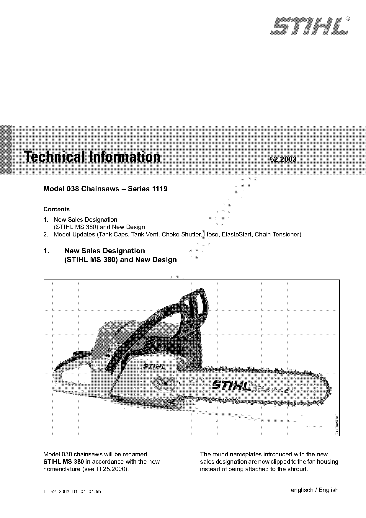
  Model 038 chainsaws will be renamed                   The round nameplates introduced with the new
  STIHL MS 380 in accordance with the new               sales designation are now clipped to the fan housing
  nomenclature (see TI 25.2000).                        instead of being attached to the shroud.

  TI_52_2003_01_01_01.fm                                                                  englisch / English
Page 2 of 6
Text of page 2 — search, copy, screen readers
Page 2                                                                                           Technical Information

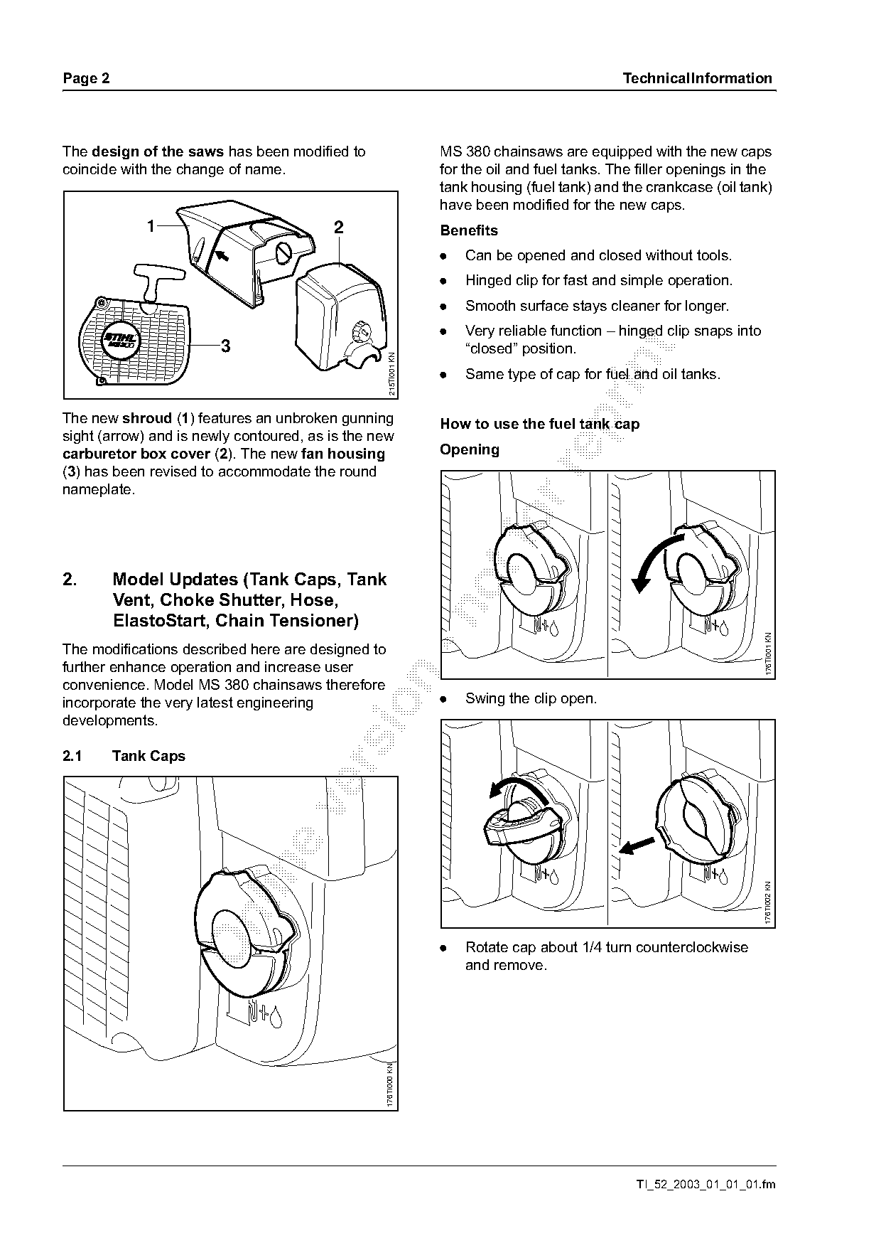
The design of the saws has been modified to                         MS 380 chainsaws are equipped with the new caps
coincide with the change of name.                                   for the oil and fuel tanks. The filler openings in the
                                                                    tank housing (fuel tank) and the crankcase (oil tank)
                                                                    have been modified for the new caps.
             1                           2                          Benefits
                                                                    .   Can be opened and closed without tools.
                                                                    .   Hinged clip for fast and simple operation.
                                                                    .   Smooth surface stays cleaner for longer.
                                                                    .   Very reliable function – hinged clip snaps into
                        3                                               “closed” position.

                                                      215TI001 KN

                                                                    .   Same type of cap for fuel and oil tanks.

The new shroud (1) features an unbroken gunning

                                                                    How to use the fuel tank cap
sight (arrow) and is newly contoured, as is the new
carburetor box cover (2). The new fan housing                       Opening
(3) has been revised to accommodate the round

nameplate.

2.       Model Updates (Tank Caps, Tank
         Vent, Choke Shutter, Hose,

         ElastoStart, Chain Tensioner)

                                                                                                                           176TI001 KN
The modifications described here are designed to
further enhance operation and increase user

convenience. Model MS 380 chainsaws therefore
incorporate the very latest engineering                             .   Swing the clip open.

developments.

2.1      Tank Caps

                                                                                                                          176TI002 KN

                                                                    .   Rotate cap about 1/4 turn counterclockwise
                                                                        and remove.
                                                   176TI000 KN

                                                                                                   TI_52_2003_01_01_01.fm
Page 3 of 6
Text of page 3 — search, copy, screen readers
Technical Information                                                                                              Page 3

Closing                                                               The previous tank vent 1117 350 5800 will be
                                                                      replaced by the new version 0000 350 5800.

                                                                      2.3     Contact Spring, Ground Wire, Retainer

                                                     176TI003 KN

                                                                                                                           215TI002 KN
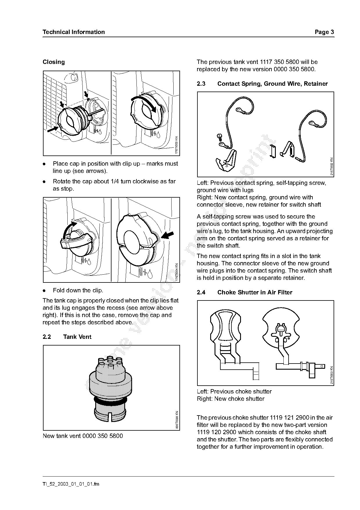
.     Place cap in position with clip up – marks must
      line up (see arrows).

.     Rotate the cap about 1/4 turn clockwise as far                  Left: Previous contact spring, self-tapping screw,
      as stop.                                                        ground wire with lugs

                                                                      Right: New contact spring, ground wire with
                                                                      connector sleeve, new retainer for switch shaft
                                                                      A self-tapping screw was used to secure the
                                                                      previous contact spring, together with the ground
                                                                      wire’s lug, to the tank housing. An upward projecting
                                                                      arm on the contact spring served as a retainer for
                                                                      the switch shaft.

                                                                      The new contact spring fits in a slot in the tank
                                                                      housing. The connector sleeve of the new ground
                                                       176TI004 KN

                                                                      wire plugs into the contact spring. The switch shaft

                                                                      is held in position by a separate retainer.

.     Fold down the clip.                                             2.4     Choke Shutter in Air Filter
The tank cap is properly closed when the clip lies flat
and its lug engages the recess (see arrow above

right). If this is not the case, remove the cap and
repeat the steps described above.

2.2      Tank Vent

                                                                                                                           215TI003 KN

                                                                      Left: Previous choke shutter
                                                                      Right: New choke shutter
                                                        000TI038 KN

                                                                      The previous choke shutter 1119 121 2900 in the air
                                                                      filter will be replaced by the new two-part version
                                                                      1119 120 2900 which consists of the choke shaft
New tank vent 0000 350 5800
                                                                      and the shutter. The two parts are flexibly connected
                                                                      together for a further improvement in operation.

TI_52_2003_01_01_01.fm
Page 4 of 6
Text of page 4 — search, copy, screen readers
Page 4                                                                                            Technical Information

2.5      Suction Hose                                              2.7     Side Chain Tensioner (Crankcase)

                                                     215TI004 KN

                                                                                                                           215TI006 KN
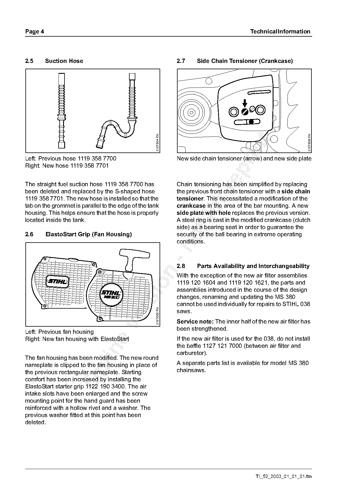
Left: Previous hose 1119 358 7700                                  New side chain tensioner (arrow) and new side plate
Right: New hose 1119 358 7701

The straight fuel suction hose 1119 358 7700 has                   Chain tensioning has been simplified by replacing

been deleted and replaced by the S-shaped hose                     the previous front chain tensioner with a side chain
1119 358 7701. The new hose is installed so that the               tensioner. This necessitated a modification of the
tab on the grommet is parallel to the edge of the tank             crankcase in the area of the bar mounting. A new
housing. This helps ensure that the hose is properly
located inside the tank.
                                                                   side plate with hole replaces the previous version.
                                                                   A steel ring is cast in the modified crankcase (clutch
                                                                   side) as a bearing seat in order to guarantee the
2.6      ElastoStart Grip (Fan Housing)                            security of the ball bearing in extreme operating
                                                                   conditions.

                                                                   2.8     Parts Availability and Interchangeability

                                                                   With the exception of the new air filter assemblies
                                                                   1119 120 1604 and 1119 120 1621, the parts and

                                                                   assemblies introduced in the course of the design
                                                                   changes, renaming and updating the MS 380
                                                                   cannot be used individually for repairs to STIHL 038
                                                     215TI005 KN

                                                                   saws.
                                                                   Service note: The inner half of the new air filter has

                                                                   been strengthened.
Left: Previous fan housing
Right: New fan housing with ElastoStart                            If the new air filter is used for the 038, do not install
                                                                   the baffle 1127 121 7000 (between air filter and

                                                                   carburetor).
The fan housing has been modified. The new round
nameplate is clipped to the fan housing in place of                A separate parts list is available for model MS 380

the previous rectangular nameplate. Starting                       chainsaws.
comfort has been increased by installing the
ElastoStart starter grip 1122 190 3400. The air
intake slots have been enlarged and the screw
mounting point for the hand guard has been
reinforced with a hollow rivet and a washer. The
previous washer fitted at this point has been
deleted.

                                                                                                    TI_52_2003_01_01_01.fm
Page 5 of 6
Text of page 5 — search, copy, screen readers
Technical Information                                                               Page 5

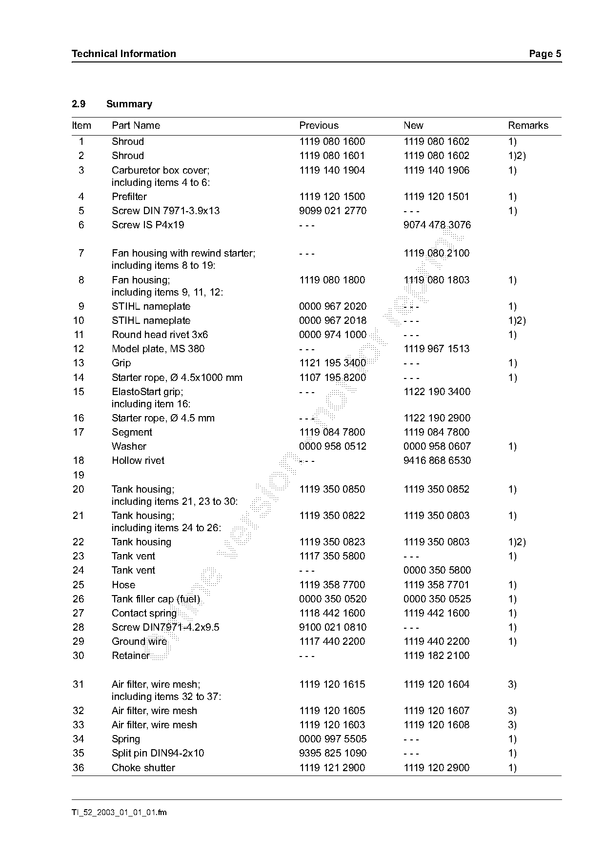
2.9     Summary

Item     Part Name                          Previous         New             Remarks
 1       Shroud                             1119 080 1600    1119 080 1602   1)
 2       Shroud                             1119 080 1601    1119 080 1602   1)2)
 3       Carburetor box cover;              1119 140 1904    1119 140 1906   1)
         including items 4 to 6:
 4       Prefilter                          1119 120 1500    1119 120 1501   1)
 5       Screw DIN 7971-3.9x13              9099 021 2770    ---             1)
 6       Screw IS P4x19                     ---              9074 478 3076

 7       Fan housing with rewind starter;   ---              1119 080 2100
         including items 8 to 19:
 8       Fan housing;                       1119 080 1800    1119 080 1803   1)

         including items 9, 11, 12:
 9       STIHL nameplate                    0000 967 2020    ---             1)
10       STIHL nameplate                    0000 967 2018    ---             1)2)

11       Round head rivet 3x6               0000 974 1000    ---             1)
12       Model plate, MS 380                ---              1119 967 1513
13
14
         Grip
         Starter rope, Ø 4.5x1000 mm
                                            1121 195 3400
                                            1107 195 8200
                                                             ---
                                                             ---
                                                                             1)
                                                                             1)
15       ElastoStart grip;                  ---              1122 190 3400
         including item 16:
16       Starter rope, Ø 4.5 mm             ---              1122 190 2900

17       Segment                            1119 084 7800    1119 084 7800
         Washer                             0000 958 0512    0000 958 0607   1)
18       Hollow rivet                       ---              9416 868 6530


20       Tank housing;                      1119 350 0850    1119 350 0852   1)
         including items 21, 23 to 30:
21       Tank housing;                      1119 350 0822    1119 350 0803   1)

         including items 24 to 26:
22       Tank housing                       1119 350 0823    1119 350 0803   1)2)

23       Tank vent                          1117 350 5800    ---             1)
24       Tank vent                          ---              0000 350 5800
25       Hose                               1119 358 7700    1119 358 7701   1)

26       Tank filler cap (fuel)             0000 350 0520    0000 350 0525   1)
27       Contact spring                     1118 442 1600    1119 442 1600   1)
28       Screw DIN7971-4.2x9.5              9100 021 0810    ---             1)

29       Ground wire                        1117 440 2200    1119 440 2200   1)
30       Retainer                           ---              1119 182 2100

31       Air filter, wire mesh;             1119 120 1615    1119 120 1604   3)
         including items 32 to 37:
32       Air filter, wire mesh              1119 120 1605    1119 120 1607   3)
33       Air filter, wire mesh              1119 120 1603    1119 120 1608   3)
34       Spring                             0000 997 5505    ---             1)
35       Split pin DIN94-2x10               9395 825 1090    ---             1)
36       Choke shutter                      1119 121 2900    1119 120 2900   1)

TI_52_2003_01_01_01.fm
Page 6 of 6
Text of page 6 — search, copy, screen readers
Page 6                                                                                  Technical Information

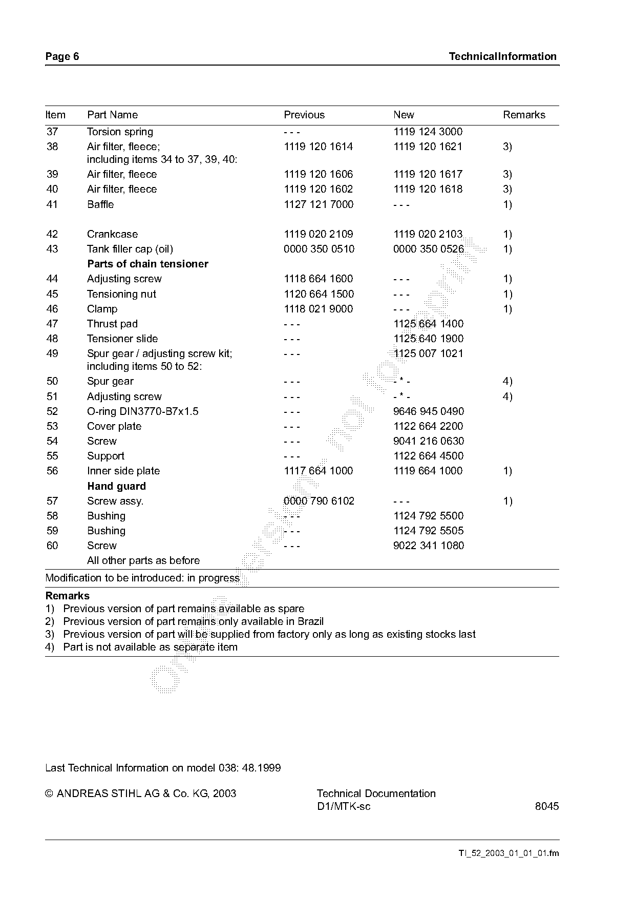
Item     Part Name                                  Previous                New                    Remarks
37       Torsion spring                             ---                     1119 124 3000
38       Air filter, fleece;                        1119 120 1614           1119 120 1621          3)
         including items 34 to 37, 39, 40:
39       Air filter, fleece                         1119 120 1606           1119 120 1617          3)
40       Air filter, fleece                         1119 120 1602           1119 120 1618          3)
41       Baffle                                     1127 121 7000           ---                    1)

42       Crankcase                                  1119 020 2109           1119 020 2103          1)
43       Tank filler cap (oil)                      0000 350 0510           0000 350 0526          1)

         Parts of chain tensioner
44       Adjusting screw                            1118 664 1600           ---                    1)
45       Tensioning nut                             1120 664 1500           ---                    1)

46       Clamp                                      1118 021 9000           ---                    1)
47       Thrust pad                                 ---                     1125 664 1400
48       Tensioner slide                            ---                     1125 640 1900

49       Spur gear / adjusting screw kit;           ---                     1125 007 1021
         including items 50 to 52:
50
51
         Spur gear
         Adjusting screw
                                                    ---
                                                    ---
                                                                    fo      -*-
                                                                            -*-
                                                                                                   4)
                                                                                                   4)
52       O-ring DIN3770-B7x1.5                      ---                     9646 945 0490
53       Cover plate                                ---                     1122 664 2200
54       Screw                                      ---                     9041 216 0630

55       Support                                    ---                     1122 664 4500
56       Inner side plate                           1117 664 1000           1119 664 1000          1)
         Hand guard

57       Screw assy.                                0000 790 6102           ---                    1)

58       Bushing                                    ---                     1124 792 5500
59       Bushing                                    ---                     1124 792 5505
60       Screw                                      ---                     9022 341 1080

         All other parts as before
Modification to be introduced: in progress

Remarks
1) Previous version of part remains available as spare
2) Previous version of part remains only available in Brazil

3) Previous version of part will be supplied from factory only as long as existing stocks last
4) Part is not available as separate item

Last Technical Information on model 038: 48.1999

© ANDREAS STIHL AG & Co. KG, 2003                          Technical Documentation
                                                           D1/MTK-sc                                      8045

                                                                                          TI_52_2003_01_01_01.fm
Most of these PDFs embed fonts with a shifted character map, so the text above was recovered rather than copied — read it as a faithful but imperfect transcription, and treat the page image above each block as the authority where the two disagree — the figures exist only there, because they are vector drawings that text extraction cannot keep.