Technical Information · issue 7 of 2004
Augmentation de la cylindrée sur MS 260 (cylindre avec piston, dissipateur de chaleur, fixation du; silencieux); Carburateur MS 260 (douille, couvercle de carter de carburateur)
Model MS 260 Chainsaws – Series 1121
IssueTI 7/2004
Engine family 1121
Full text
Page 1 of 5
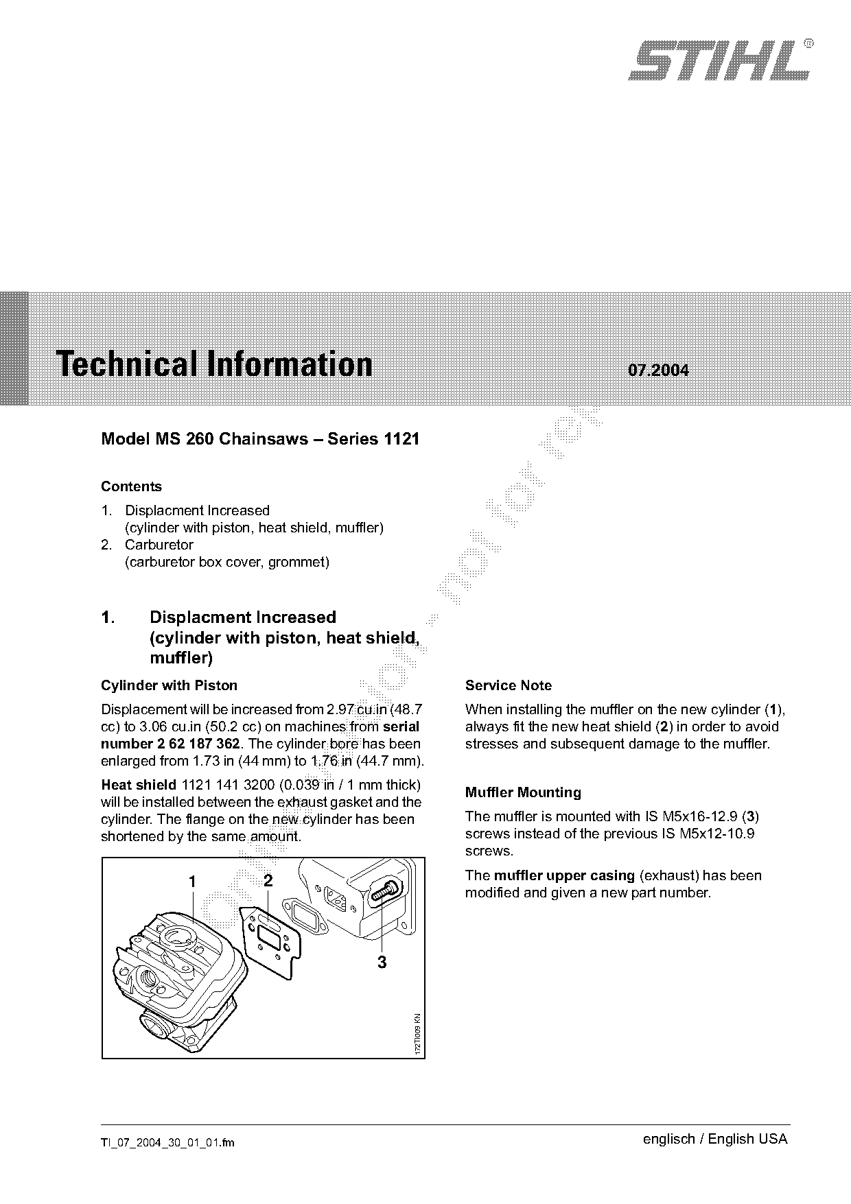
Text of page 1 — search, copy, screen readers
STIH)

Technical Information

                                                                                            07.2004

  Model MS 260 Chainsaws – Series 1121

  Contents
  1. Displacment Increased
     (cylinder with piston, heat shield, muffler)
  2. Carburetor
     (carburetor box cover, grommet)

  1.      Displacment Increased
          (cylinder with piston, heat shield,

          muffler)

  Cylinder with Piston                                            Service Note
  Displacement will be increased from 2.97 cu.in (48.7            When installing the muffler on the new cylinder (1),
  cc) to 3.06 cu.in (50.2 cc) on machines from serial             always fit the new heat shield (2) in order to avoid

  number 2 62 187 362. The cylinder bore has been                 stresses and subsequent damage to the muffler.
  enlarged from 1.73 in (44 mm) to 1.76 in (44.7 mm).

  Heat shield 1121 141 3200 (0.039 in / 1 mm thick)
                                                                  Muffler Mounting
  will be installed between the exhaust gasket and the
  cylinder. The flange on the new cylinder has been               The muffler is mounted with IS M5x16-12.9 (3)
  shortened by the same amount.                                   screws instead of the previous IS M5x12-10.9

                                                                  screws.

                1            2                                    The muffler upper casing (exhaust) has been

                                                                  modified and given a new part number.

                                               3
                                                    172TI009 KN

  TI_07_2004_30_01_01.fm                                                                      englisch / English USA
Page 2 of 5
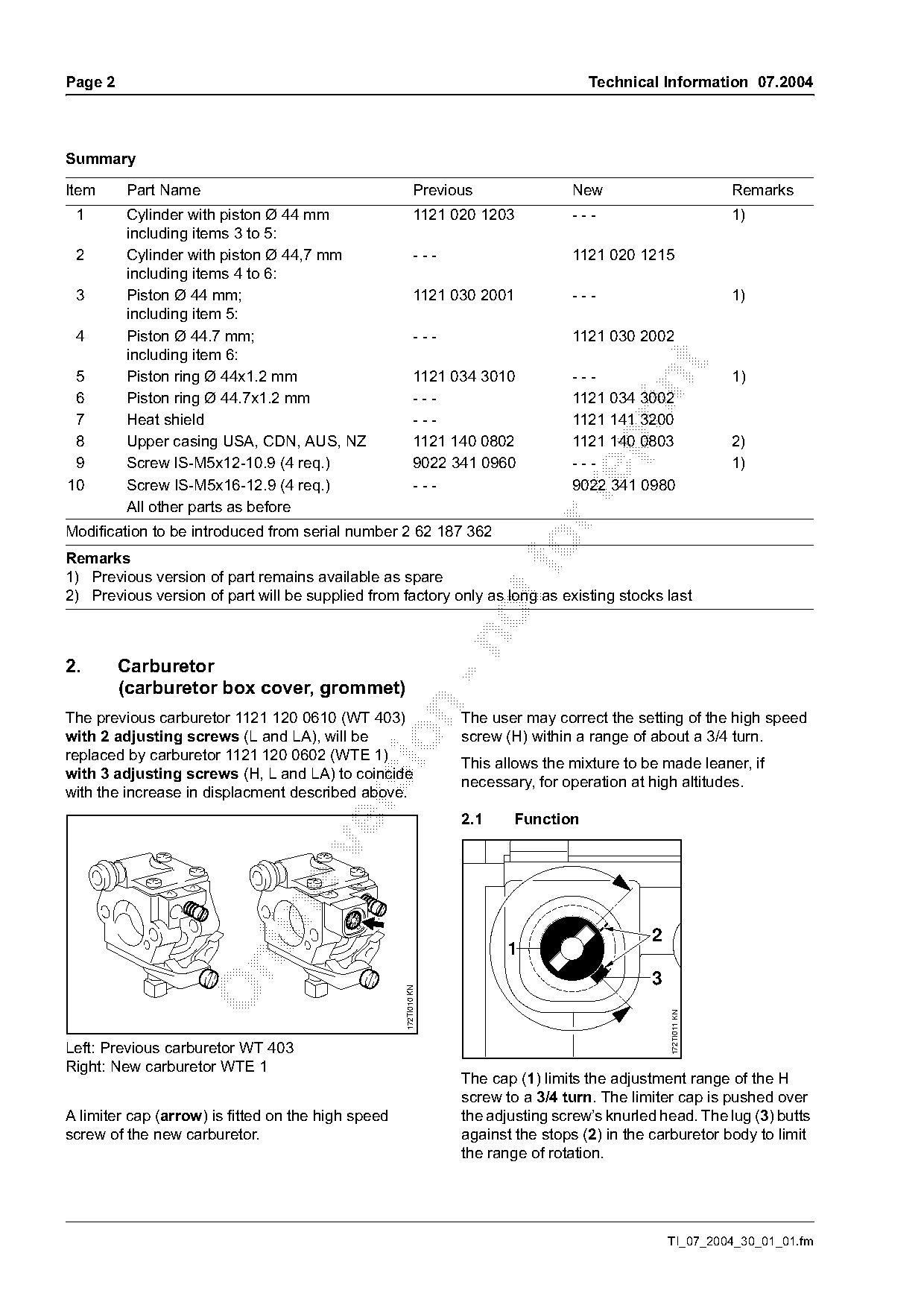
Text of page 2 — search, copy, screen readers
Page 2                                                                               Technical Information 07.2004

Summary

Item     Part Name                                         Previous               New                           Remarks
 1       Cylinder with piston Ø 44 mm                      1121 020 1203          ---                           1)
         including items 3 to 5:
 2       Cylinder with piston Ø 44,7 mm                    ---                    1121 020 1215
         including items 4 to 6:
 3       Piston Ø 44 mm;                                   1121 030 2001          ---                           1)
         including item 5:
 4       Piston Ø 44.7 mm;                                 ---                    1121 030 2002
         including item 6:

 5       Piston ring Ø 44x1.2 mm                           1121 034 3010          ---                           1)

 6       Piston ring Ø 44.7x1.2 mm                         ---                    1121 034 3002
 7       Heat shield                                       ---                    1121 141 3200
 8       Upper casing USA, CDN, AUS, NZ                    1121 140 0802          1121 140 0803                 2)

 9       Screw IS-M5x12-10.9 (4 req.)                      9022 341 0960          ---                           1)
10       Screw IS-M5x16-12.9 (4 req.)                      ---                    9022 341 0980

         All other parts as before
Modification to be introduced from serial number 2 62 187 362
Remarks
1) Previous version of part remains available as spare
2) Previous version of part will be supplied from factory only as long as existing stocks last

2.       Carburetor
         (carburetor box cover, grommet)

The previous carburetor 1121 120 0610 (WT 403)                    The user may correct the setting of the high speed
with 2 adjusting screws (L and LA), will be                       screw (H) within a range of about a 3/4 turn.

replaced by carburetor 1121 120 0602 (WTE 1)
                                                                  This allows the mixture to be made leaner, if
with 3 adjusting screws (H, L and LA) to coincide
                                                                  necessary, for operation at high altitudes.
with the increase in displacment described above.

                                                                  2.1     Function

                                                                                              2
                                                                        1

                                                                                              3
                                                    172TI010 KN

                                                                                                  172TI011 KN

Left: Previous carburetor WT 403
Right: New carburetor WTE 1
                                                                  The cap (1) limits the adjustment range of the H
                                                                  screw to a 3/4 turn. The limiter cap is pushed over
A limiter cap (arrow) is fitted on the high speed                 the adjusting screw’s knurled head. The lug (3) butts
screw of the new carburetor.                                      against the stops (2) in the carburetor body to limit
                                                                  the range of rotation.

                                                                                                  TI_07_2004_30_01_01.fm
Page 3 of 5
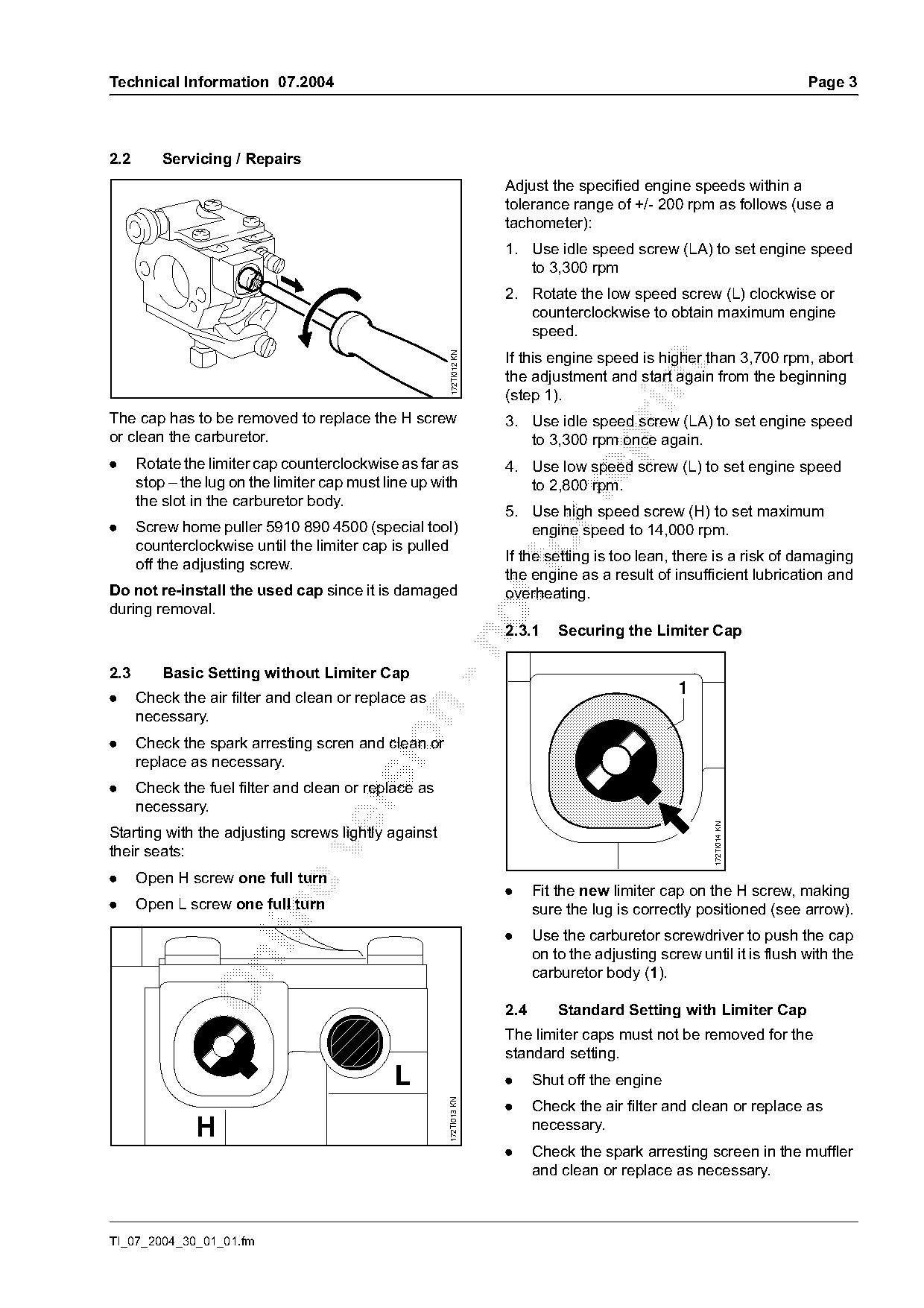
Text of page 3 — search, copy, screen readers
Technical Information 07.2004                                                                                          Page 3

2.2       Servicing / Repairs
                                                                     Adjust the specified engine speeds within a
                                                                     tolerance range of +/- 200 rpm as follows (use a
                                                                     tachometer):
                                                                     1. Use idle speed screw (LA) to set engine speed
                                                                        to 3,300 rpm
                                                                     2. Rotate the low speed screw (L) clockwise or
                                                                        counterclockwise to obtain maximum engine
                                                                        speed.
                                                                     If this engine speed is higher than 3,700 rpm, abort

                                                       172TI012 KN

                                                                     the adjustment and start again from the beginning

                                                                     (step 1).
The cap has to be removed to replace the H screw                     3. Use idle speed screw (LA) to set engine speed
or clean the carburetor.                                                to 3,300 rpm once again.

.     Rotate the limiter cap counterclockwise as far as              4. Use low speed screw (L) to set engine speed
      stop – the lug on the limiter cap must line up with               to 2,800 rpm.

      the slot in the carburetor body.
                                                                     5. Use high speed screw (H) to set maximum
.     Screw home puller 5910 890 4500 (special tool)                    engine speed to 14,000 rpm.
      counterclockwise until the limiter cap is pulled
      off the adjusting screw.
                                                                     If the setting is too lean, there is a risk of damaging
                                                                     the engine as a result of insufficient lubrication and
Do not re-install the used cap since it is damaged                   overheating.
during removal.
                                                                     2.3.1     Securing the Limiter Cap

2.3       Basic Setting without Limiter Cap
.     Check the air filter and clean or replace as
                                                                                                  1

      necessary.

.     Check the spark arresting scren and clean or
      replace as necessary.
.     Check the fuel filter and clean or replace as

      necessary.
                                                                                                        172TI014 KN

Starting with the adjusting screws lightly against

their seats:
.     Open H screw one full turn
                                                                     .     Fit the new limiter cap on the H screw, making
.     Open L screw one full turn                                           sure the lug is correctly positioned (see arrow).

                                                                     .     Use the carburetor screwdriver to push the cap
                                                                           on to the adjusting screw until it is flush with the

                                                                           carburetor body (1).

                                                                     2.4       Standard Setting with Limiter Cap
                                                                     The limiter caps must not be removed for the
                                                                     standard setting.
                                              L                      .     Shut off the engine
                                                                     .
                                                       172TI013 KN

                                                                           Check the air filter and clean or replace as
               H                                                           necessary.
                                                                     .     Check the spark arresting screen in the muffler
                                                                           and clean or replace as necessary.

TI_07_2004_30_01_01.fm
Page 4 of 5
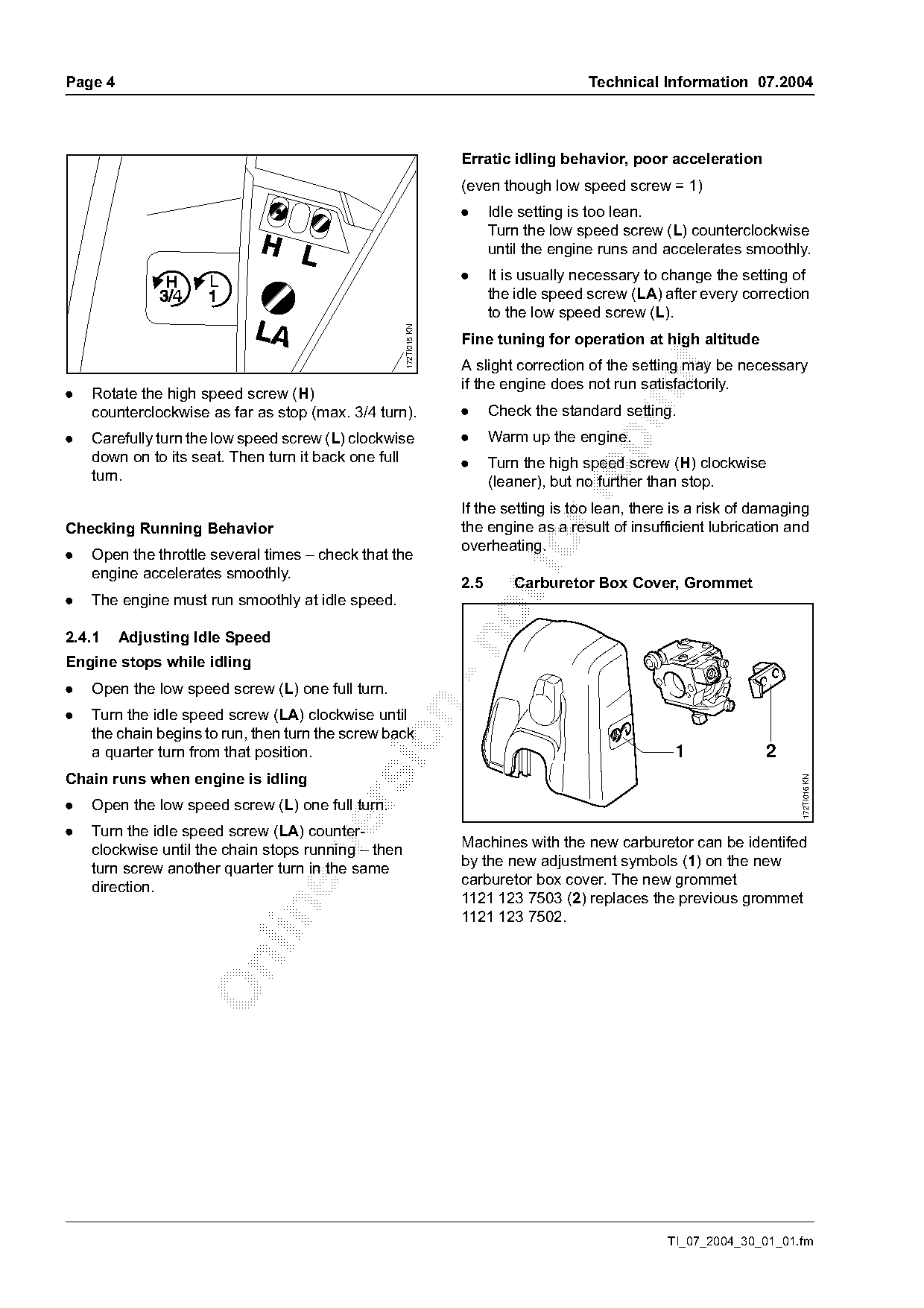
Text of page 4 — search, copy, screen readers
Page 4                                                                                  Technical Information 07.2004

                                                                   Erratic idling behavior, poor acceleration
                                                                   (even though low speed screw = 1)
                                                                   .     Idle setting is too lean.
                                                                         Turn the low speed screw (L) counterclockwise
                                                                         until the engine runs and accelerates smoothly.

                     L                                             .     It is usually necessary to change the setting of
                                                                         the idle speed screw (LA) after every correction
                                                                         to the low speed screw (L).

                                                     172TI015 KN
                                                                   Fine tuning for operation at high altitude
                                                                   A slight correction of the setting may be necessary

                                                                   if the engine does not run satisfactorily.
.   Rotate the high speed screw (H)
    counterclockwise as far as stop (max. 3/4 turn).               .     Check the standard setting.
.   Carefully turn the low speed screw (L) clockwise               .     Warm up the engine.

    down on to its seat. Then turn it back one full                .     Turn the high speed screw (H) clockwise
    turn.                                                                (leaner), but no further than stop.

                                                                   If the setting is too lean, there is a risk of damaging
Checking Running Behavior                                          the engine as a result of insufficient lubrication and
.   Open the throttle several times – check that the
    engine accelerates smoothly.
                                                                   overheating.

                                                                   2.5      Carburetor Box Cover, Grommet
.   The engine must run smoothly at idle speed.

2.4.1    Adjusting Idle Speed

Engine stops while idling
.   Open the low speed screw (L) one full turn.

.   Turn the idle speed screw (LA) clockwise until
    the chain begins to run, then turn the screw back

    a quarter turn from that position.                                                              1              2
Chain runs when engine is idling
.                                                                                                                       172TI016 KN

    Open the low speed screw (L) one full turn.
.   Turn the idle speed screw (LA) counter-
                                                                   Machines with the new carburetor can be identifed

    clockwise until the chain stops running – then
                                                                   by the new adjustment symbols (1) on the new
    turn screw another quarter turn in the same
                                                                   carburetor box cover. The new grommet
    direction.
                                                                   1121 123 7503 (2) replaces the previous grommet

                                                                   1121 123 7502.

                                                                                                   TI_07_2004_30_01_01.fm
Page 5 of 5
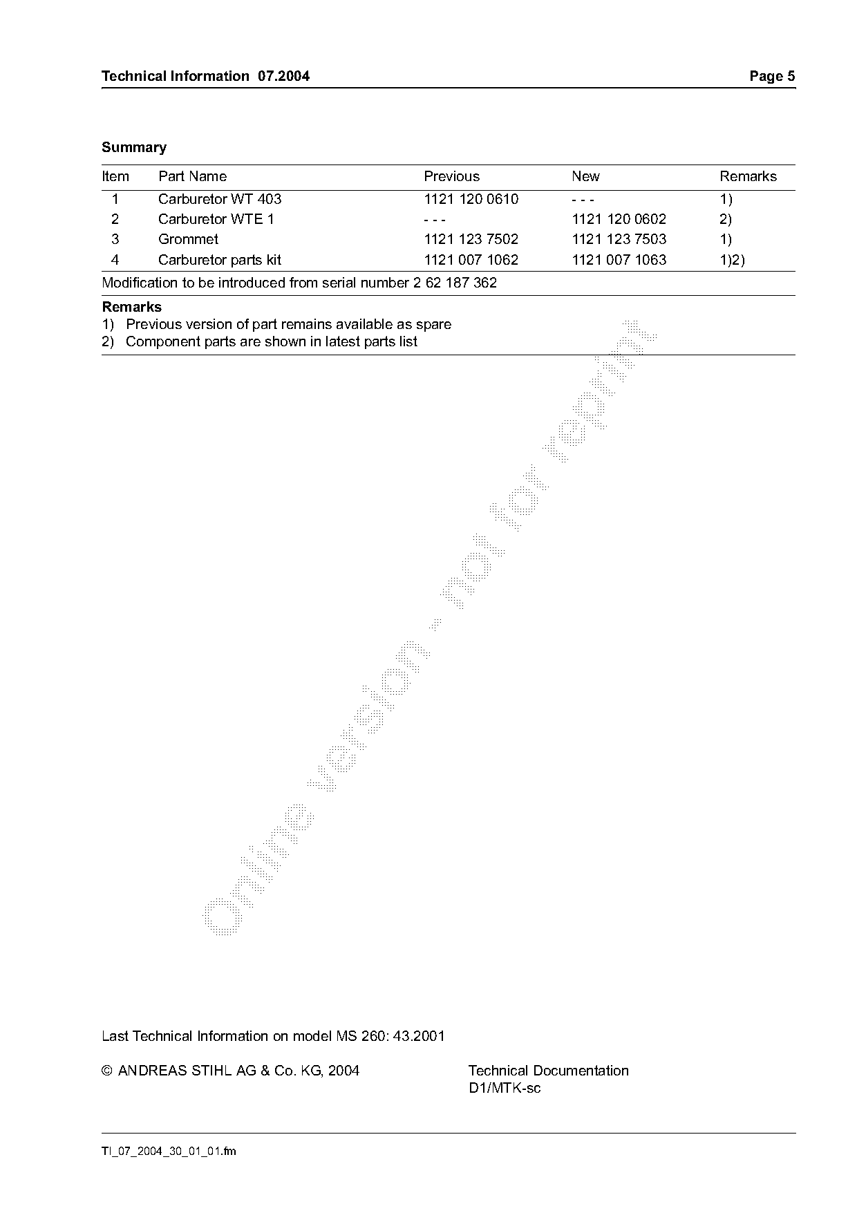
Text of page 5 — search, copy, screen readers
Technical Information 07.2004                                                                 Page 5

Summary

Item     Part Name                               Previous              New             Remarks
 1       Carburetor WT 403                       1121 120 0610         ---             1)
 2       Carburetor WTE 1                        ---                   1121 120 0602   2)
 3       Grommet                                 1121 123 7502         1121 123 7503   1)
 4       Carburetor parts kit                    1121 007 1062         1121 007 1063   1)2)
Modification to be introduced from serial number 2 62 187 362
Remarks
1) Previous version of part remains available as spare

2) Component parts are shown in latest parts list

Last Technical Information on model MS 260: 43.2001

© ANDREAS STIHL AG & Co. KG, 2004                        Technical Documentation
                                                         D1/MTK-sc

TI_07_2004_30_01_01.fm
Most of these PDFs embed fonts with a shifted character map, so the text above was recovered rather than copied — read it as a faithful but imperfect transcription, and treat the page image above each block as the authority where the two disagree — the figures exist only there, because they are vector drawings that text extraction cannot keep.