Technical Information · issue 10 of 2004
Chain catcher; Annular buffer, tank housing
IssueTI 10/2004
Engine family 1135
Full text
Page 1 of 4
Text of page 1 — search, copy, screen readers
STIH)

Technical Information                                                                           10.2004

  Chainsaws STIHL MS 361 – Series 1135

  Contents
  1. Chain catcher
  2. Annular buffer, tank housing

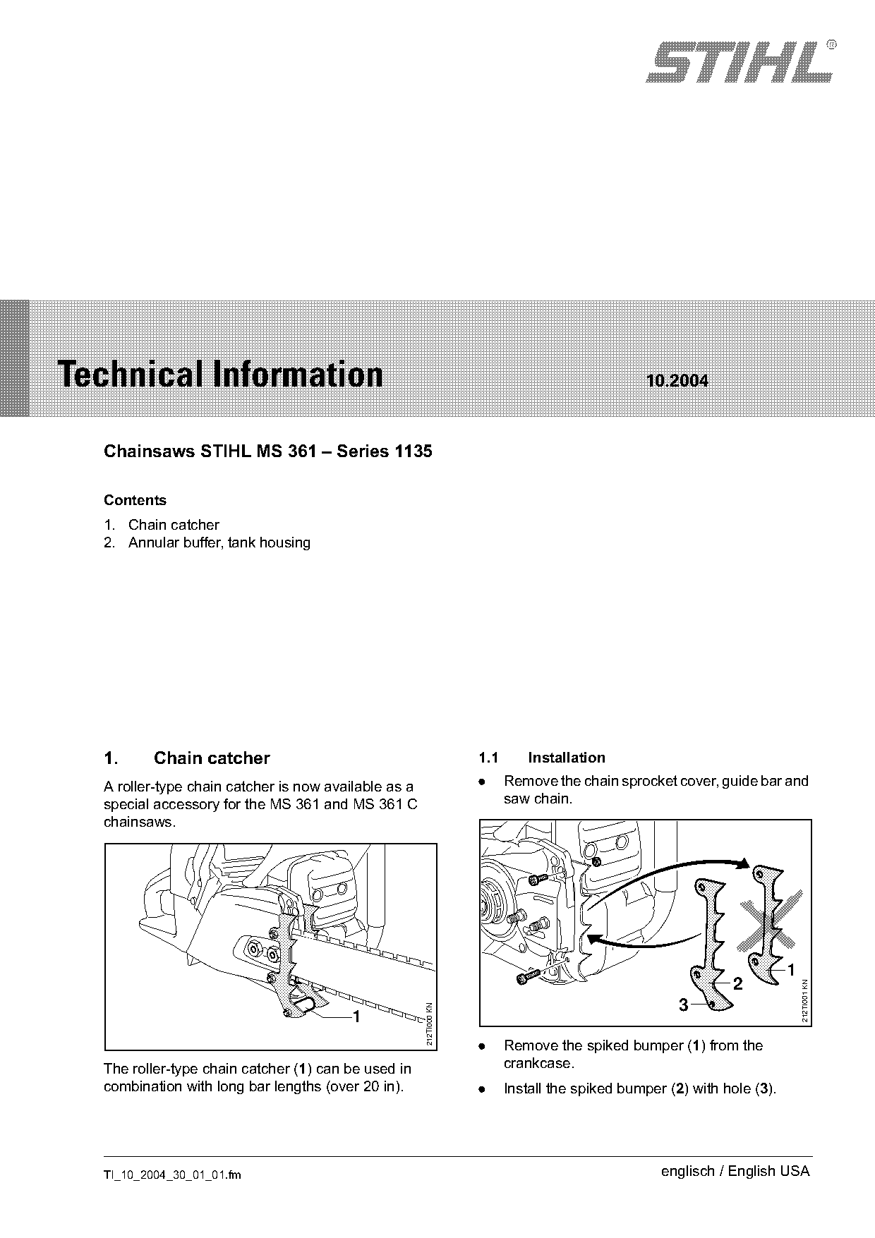
  1.     Chain catcher                                              1.1       Installation

  A roller-type chain catcher is now available as a                 .     Remove the chain sprocket cover, guide bar and
  special accessory for the MS 361 and MS 361 C                           saw chain.
  chainsaws.

                                                                                                                         1
                                                                                                              2
                                                                                                                             212TI001 KN

                                                                                                      3
                                                      212TI000 KN

                                        1
                                                                    .     Remove the spiked bumper (1) from the
  The roller-type chain catcher (1) can be used in                        crankcase.
  combination with long bar lengths (over 20 in).                   .     Install the spiked bumper (2) with hole (3).

  TI_10_2004_30_01_01.fm                                                                           englisch / English USA
Page 2 of 4
Text of page 2 — search, copy, screen readers
Page 2                                                                                Technical Information 10.2004

    1
                                                                              2

                                                 212TI002 KN

                                                                                                                        212TI004 KN
                                             1                                1

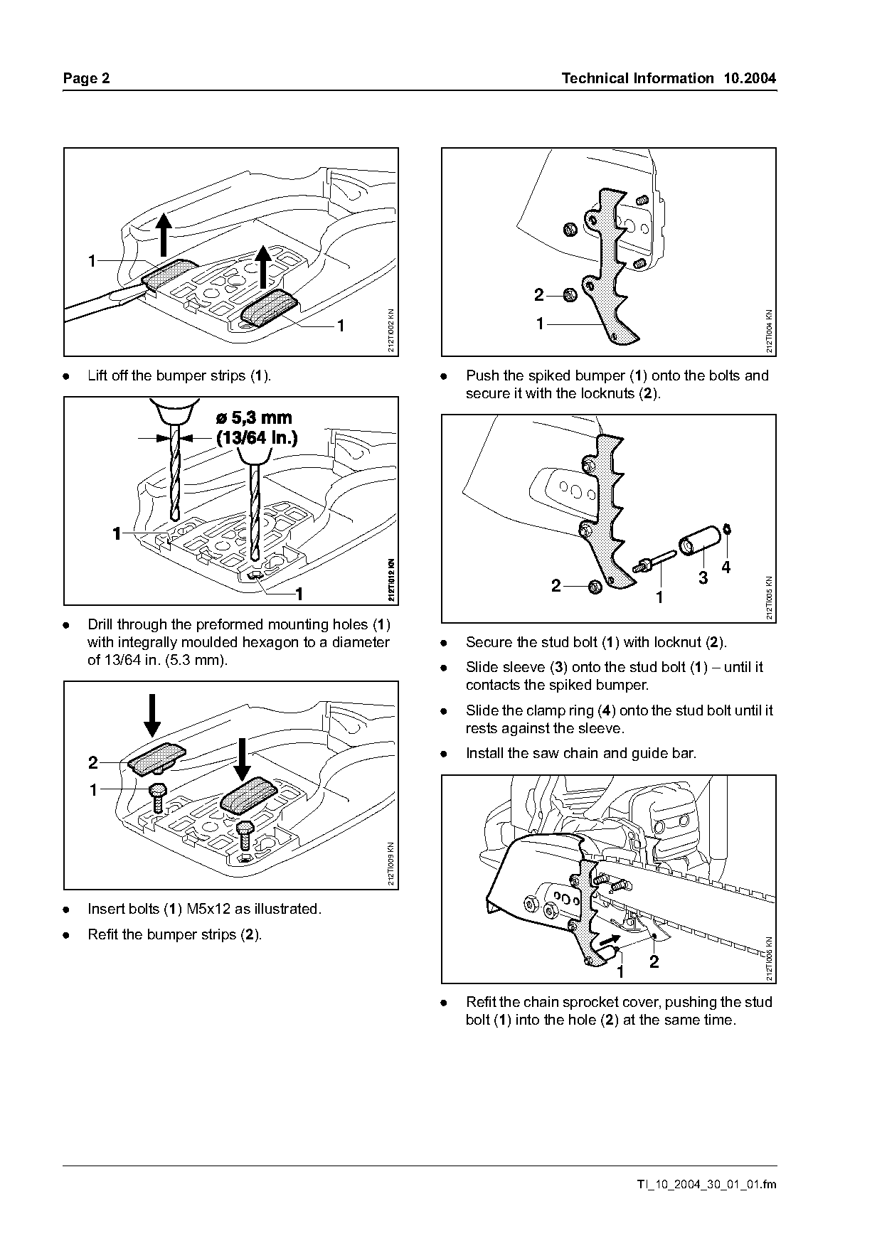
.   Lift off the bumper strips (1).                            .   Push the spiked bumper (1) onto the bolts and
                                                                   secure it with the locknuts (2).

                                                                                                              4
                                                                                                          3

                                                                                                                        212TI005 KN
                                                                                  2
                                                                                                   1
.   Drill through the preformed mounting holes (1)
    with integrally moulded hexagon to a diameter              .   Secure the stud bolt (1) with locknut (2).
    of 13/64 in. (5.3 mm).
                                                               .   Slide sleeve (3) onto the stud bolt (1) – until it
                                                                   contacts the spiked bumper.
                                                               .   Slide the clamp ring (4) onto the stud bolt until it
                                                                   rests against the sleeve.
                                                               .   Install the saw chain and guide bar.
    2
    1
                                                 212TI009 KN

.   Insert bolts (1) M5x12 as illustrated.
.   Refit the bumper strips (2).
                                                                                                                        212TI006 KN

                                                                                                  2
                                                                                             1
                                                               .   Refit the chain sprocket cover, pushing the stud
                                                                   bolt (1) into the hole (2) at the same time.

                                                                                                 TI_10_2004_30_01_01.fm
Page 3 of 4
Text of page 3 — search, copy, screen readers
Technical Information 10.2004                                                                                   Page 3

1.2     Summary

Item     Part name                                         Part No.                                        Rem.
 1       Chain catcher;
         including Items 2 to 9:                           1135 650 7750
 2       Spiked bumper                                     1135 664 0500
 3       Spiked bumper                                     1135 664 0501
 4       Hex bolt M5x12                                    9008 319 0960
 5       Chain catcher;
         including Items 6 to 9:                           1135 650 7700
 6       Stud bolt                                         -*-                                             1)
 7       Sleeve                                            1135 656 6600
 8       Locknut M5-10                                     9214 320 0700
 9       Clamp ring 5x0.8                                  9452 621 0140
Modification to be introduced continuously
Remarks
1) Part is not available separately as a spare part

2.     Annular buffer, tank housing
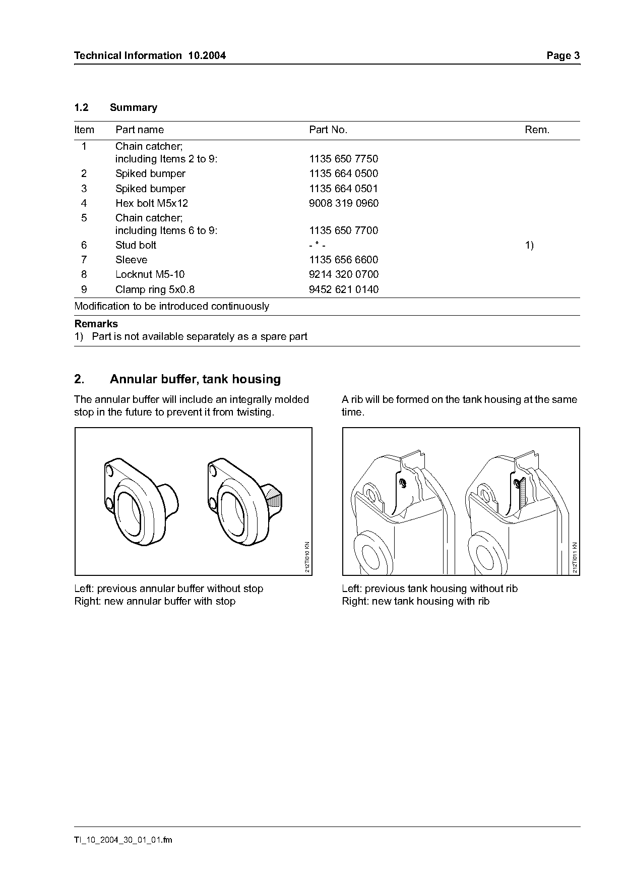
The annular buffer will include an integrally molded             A rib will be formed on the tank housing at the same
stop in the future to prevent it from twisting.                  time.
                                                   212TI010 KN

                                                                                                                    212TI011 KN

Left: previous annular buffer without stop                       Left: previous tank housing without rib
Right: new annular buffer with stop                              Right: new tank housing with rib

TI_10_2004_30_01_01.fm
Page 4 of 4
Text of page 4 — search, copy, screen readers
Page 4                                                                             Technical Information 10.2004


                                                     212TI008 KN
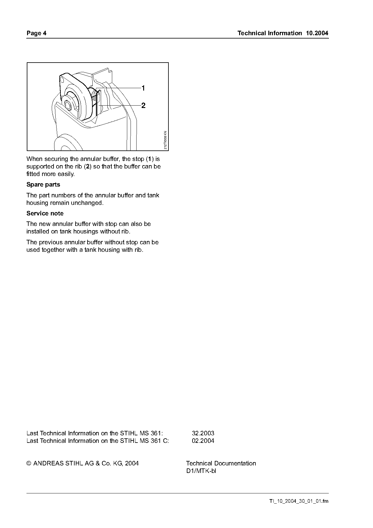
When securing the annular buffer, the stop (1) is
supported on the rib (2) so that the buffer can be
fitted more easily.
Spare parts
The part numbers of the annular buffer and tank
housing remain unchanged.
Service note
The new annular buffer with stop can also be
installed on tank housings without rib.
The previous annular buffer without stop can be
used together with a tank housing with rib.

Last Technical Information on the STIHL MS 361:                     32.2003
Last Technical Information on the STIHL MS 361 C:                   02.2004

© ANDREAS STIHL AG & Co. KG, 2004                                  Technical Documentation
                                                                   D1/MTK-bl

                                                                                             TI_10_2004_30_01_01.fm
Most of these PDFs embed fonts with a shifted character map, so the text above was recovered rather than copied — read it as a faithful but imperfect transcription, and treat the page image above each block as the authority where the two disagree — the figures exist only there, because they are vector drawings that text extraction cannot keep.