Technical Information · issue 37 of 2004
Technical Description; Mounting the Cultivator; Mounting the Rotor Blades; Specifications; Service Accessories; Spare Parts; Repairs; Repair Times
IssueTI 37/2004
Full text
Page 1 of 5
Text of page 1 — search, copy, screen readers
STIH)

Technical Information                                                   37.2004

  New STIHL BF Attachment – Series 4601
  New STIHL BF-KM KombiTool – Series 4601

  Contents
  1.   Technical Description
  2.   Mounting the Cultivator
  3.   Mounting the Rotor Blades
  4.   Specifications
  5.   Service Accessories
  6.   Spare Parts
  7.   Repairs

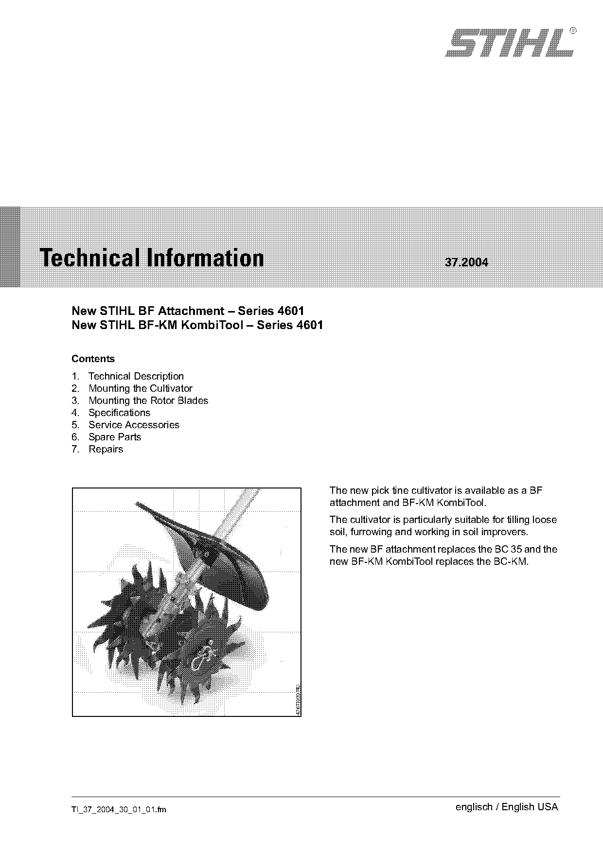
                                            The new pick tine cultivator is available as a BF
                                            attachment and BF-KM KombiTool.
                                            The cultivator is particularly suitable for tilling loose
                                            soil, furrowing and working in soil improvers.
                                            The new BF attachment replaces the BC 35 and the
                                            new BF-KM KombiTool replaces the BC-KM.

  TI_37_2004_30_01_01.fm                                                   englisch / English USA
Page 2 of 5
Text of page 2 — search, copy, screen readers
Page 2                                                                    Technical Information 37.2004

1.       Technical Description                         2.1.2   Preparations

The worm gear drive has a reduction ratio of 44:1 to   .   Loosen the clamp screws on the basic power
bring the engine speed down to the speed                   tool’s gearbox housing and pull the gearbox off
necessary for tilling. The rotor blades may be             the drive tube.
removed and replaced individually.                     The drive shaft may slip out of the tube in this
Four rotor blades come standard with the pick tine     process. If this happens, push the drive shaft back
cultivator and are already mounted at the factory.     into the tube.

2.       Mounting the Cultivator

2.1      BF Attachment

2.1.1    Approved Basic Power Tools:
Bike-handled or loop-handled machines with
barrier bar
STIHL FS 851), STIHL FS 1001), STIHL FS 1101),
STIHL FS 120, STIHL FS 200, STIHL FS 250,
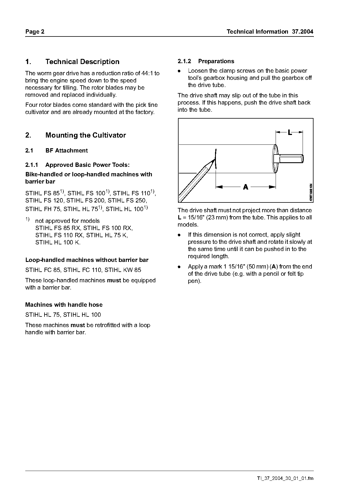
STIHL FH 75, STIHL HL 751), STIHL HL 1001)             The drive shaft must not project more than distance
1)                                                     L = 15/16" (23 mm) from the tube. This applies to all
      not approved for models
                                                       models.
      STIHL FS 85 RX, STIHL FS 100 RX,
      STIHL FS 110 RX, STIHL HL 75 K,                  .   If this dimension is not correct, apply slight
      STIHL HL 100 K.                                      pressure to the drive shaft and rotate it slowly at
                                                           the same time until it can be pushed in to the
                                                           required length.
Loop-handled machines without barrier bar
                                                       .   Apply a mark 1 15/16" (50 mm) (A) from the end
STIHL FC 85, STIHL FC 110, STIHL KW 85
                                                           of the drive tube (e.g. with a pencil or felt tip
These loop-handled machines must be equipped               pen).
with a barrier bar.

Machines with handle hose
STIHL HL 75, STIHL HL 100
These machines must be retrofitted with a loop
handle with barrier bar.

                                                                                       TI_37_2004_30_01_01.fm
Page 3 of 5
Text of page 3 — search, copy, screen readers
Technical Information 37.2004                                                                                Page 3

2.1.3   Mounting the Deflector                            2.2       BF-KM KombiTool

                                                          2.2.1     Approved KombiEngines:
                                                          STIHL KM 55, STIHL KM 85, STIHL KM 110
                                                          STIHL FS 55 RT, STIHL FS 85 RT,
                                                          Machines with a loop handle must be equipped with
                                                          a barrier bar.

                                                          2.2.2     Preparations

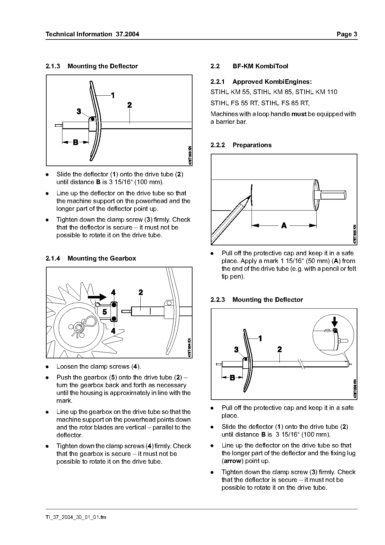
.   Slide the deflector (1) onto the drive tube (2)
    until distance B is 3 15/16“ (100 mm).
.   Line up the deflector on the drive tube so that
    the machine support on the powerhead and the
    longer part of the deflector point up.
.   Tighten down the clamp screw (3) firmly. Check
    that the deflector is secure – it must not be
    possible to rotate it on the drive tube.

                                                          .     Pull off the protective cap and keep it in a safe
2.1.4   Mounting the Gearbox                                    place. Apply a mark 1 15/16“ (50 mm) (A) from
                                                                the end of the drive tube (e.g. with a pencil or felt
                                                                tip pen).

                                                          2.2.3     Mounting the Deflector

.   Loosen the clamp screws (4).
.   Push the gearbox (5) onto the drive tube (2) –
    turn the gearbox back and forth as necessary
    until the housing is approximately in line with the
    mark.
                                                          .     Pull off the protective cap and keep it in a safe
.   Line up the gearbox on the drive tube so that the
                                                                place.
    machine support on the powerhead points down
    and the rotor blades are vertical – parallel to the   .     Slide the deflector (1) onto the drive tube (2)
    deflector.                                                  until distance B is 3 15/16“ (100 mm).
.   Tighten down the clamp screws (4) firmly. Check       .     Line up the deflector on the drive tube so that
    that the gearbox is secure – it must not be                 the longer part of the deflector and the fixing lug
    possible to rotate it on the drive tube.                    (arrow) point up.
                                                          .     Tighten down the clamp screw (3) firmly. Check
                                                                that the deflector is secure – it must not be
                                                                possible to rotate it on the drive tube.

TI_37_2004_30_01_01.fm
Page 4 of 5
Text of page 4 — search, copy, screen readers
Page 4                                                                          Technical Information 37.2004

2.2.4    Mounting the Gearbox                               3.       Mounting the Rotor Blades
                                                            The rotor blades are already mounted at the factory.

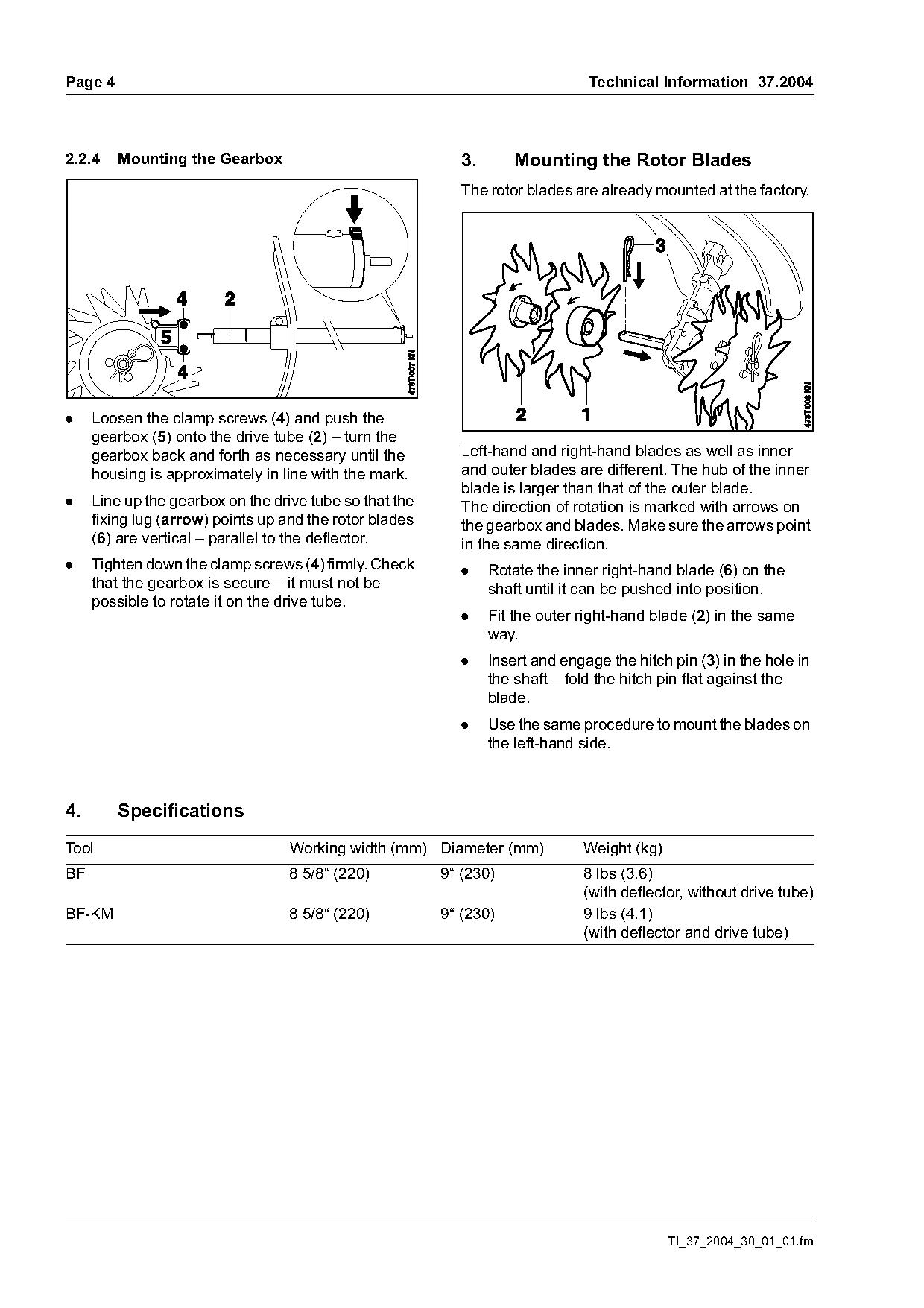
.    Loosen the clamp screws (4) and push the
     gearbox (5) onto the drive tube (2) – turn the
     gearbox back and forth as necessary until the          Left-hand and right-hand blades as well as inner
     housing is approximately in line with the mark.        and outer blades are different. The hub of the inner
                                                            blade is larger than that of the outer blade.
.    Line up the gearbox on the drive tube so that the      The direction of rotation is marked with arrows on
     fixing lug (arrow) points up and the rotor blades      the gearbox and blades. Make sure the arrows point
     (6) are vertical – parallel to the deflector.          in the same direction.
.    Tighten down the clamp screws (4) firmly. Check        .    Rotate the inner right-hand blade (6) on the
     that the gearbox is secure – it must not be                 shaft until it can be pushed into position.
     possible to rotate it on the drive tube.
                                                            .    Fit the outer right-hand blade (2) in the same
                                                                 way.
                                                            .    Insert and engage the hitch pin (3) in the hole in
                                                                 the shaft – fold the hitch pin flat against the
                                                                 blade.
                                                            .    Use the same procedure to mount the blades on
                                                                 the left-hand side.

4.       Specifications
Tool                               Working width (mm) Diameter (mm)            Weight (kg)
BF                                 8 5/8“ (220)          9“ (230)              8 lbs (3.6)
                                                                               (with deflector, without drive tube)
BF-KM                              8 5/8“ (220)          9“ (230)              9 lbs (4.1)
                                                                               (with deflector and drive tube)

                                                                                             TI_37_2004_30_01_01.fm
Page 5 of 5
Text of page 5 — search, copy, screen readers
Technical Information 37.2004                                                    Page 5

5.      Service Accessories
Available special servicing tools are listed in the
STIHL KombiTools service manual.

6.      Spare Parts
The illustrated parts list for BF-MM may be used
until separate parts lists are available.

7.      Repairs
If the machine is started up in the course of
repairs, it is essential to observe all country-
specific safety regulations and the safety
precautions outlined in the instruction manual.

7.1     Service Note
For servicing and repair procedures on the engine
refer to the service manual for STIHL KombiTools.

7.2     Gearbox
Gear lubricant 0781 120 1004 (2 oz / 60 g can) is
available for repairs to the gearbox.
The gearbox is packed with 0.95 - 1.1 oz (30 - 35 g)
lubricant.
The gearbox is maintenance-free. It need only be
refilled with fresh lubricant after repairs, e.g.
replacing parts.

© 2004 Andreas Stihl AG & Co. KG                       Technical Documentation
  Waiblingen                                           D1/MTK-na

TI_37_2004_30_01_01.fm
Most of these PDFs embed fonts with a shifted character map, so the text above was recovered rather than copied — read it as a faithful but imperfect transcription, and treat the page image above each block as the authority where the two disagree — the figures exist only there, because they are vector drawings that text extraction cannot keep.