Technical Information · issue 41 of 2004
Technical description; Specifications; Cutting tools; Accessories; Service accessories; Service note; Spare parts
IssueTI 41/2004
Full text
Page 1 of 10
Text of page 1 — search, copy, screen readers
STIH)

Technical Information                                               41.2004

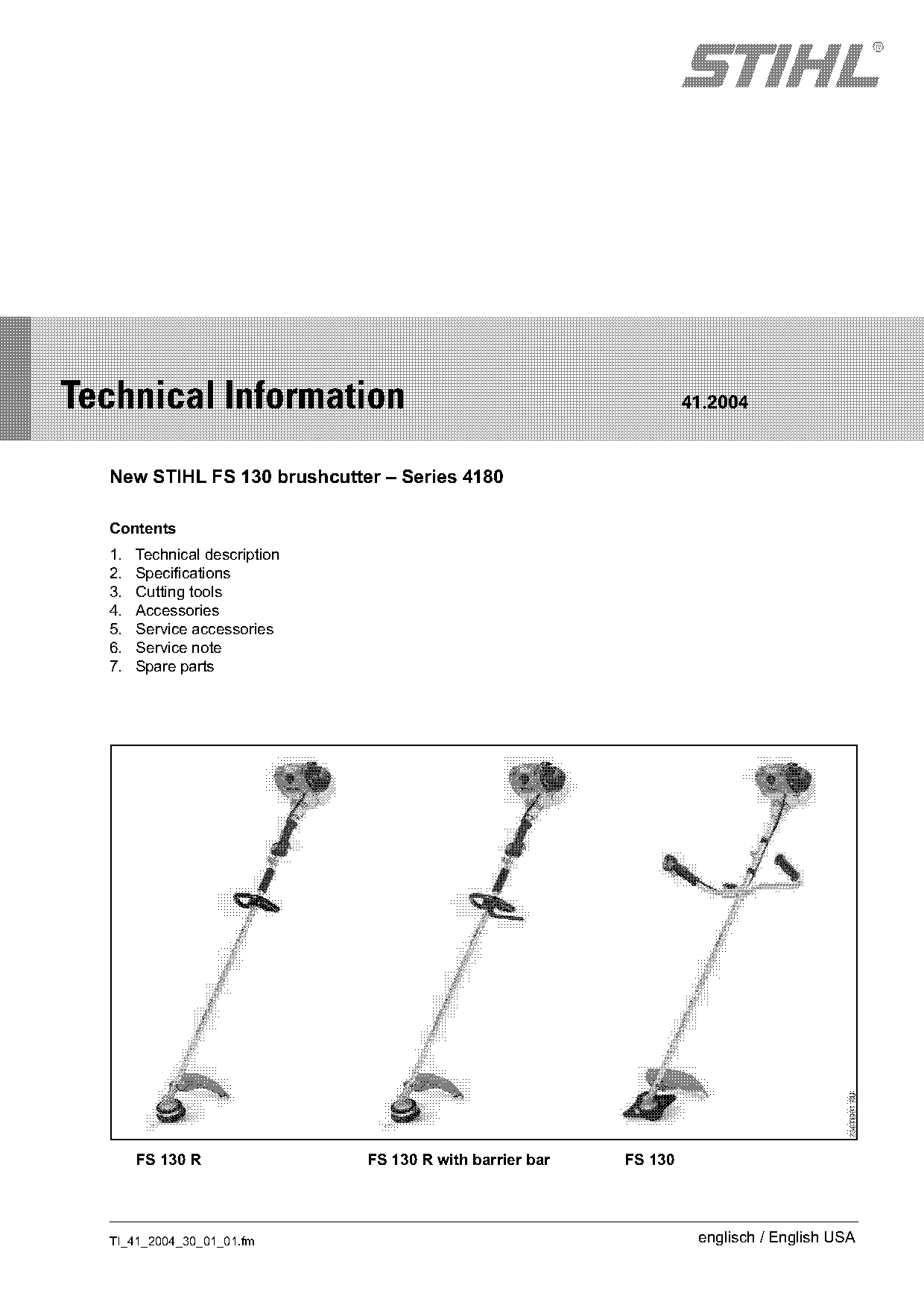
  New STIHL FS 130 brushcutter – Series 4180

  Contents
  1.   Technical description
  2.   Specifications
  3.   Cutting tools
  4.   Accessories
  5.   Service accessories
  6.   Service note
  7.   Spare parts

       FS 130 R                FS 130 R with barrier bar   FS 130

  TI_41_2004_30_01_01.fm                                             englisch / English USA
Page 2 of 10
Text of page 2 — search, copy, screen readers
Page 2                                                                      Technical Information 41.2004

The new STIHL FS 130 brushcutter with 4-MIX®             1.1.1   Engine design
engine is the latest addition to the range of powerful   Single-cylinder engine with overhead valves.
brushcutters. It is positioned in the STIHL range        Cylinder head, cylinder and the upper half of the
between the models FS 110 and FS 250.                    crankcase are combined into a single component.
                                                         The crankcase is horizontally split in line with the
The 4-MIX® engine operates with the patented
                                                         crankshaft.
STIHL lubrication system. The charge cycle is
based on the four-stroke principle.
The STIHL 4-MIX® engine uses the same fuel
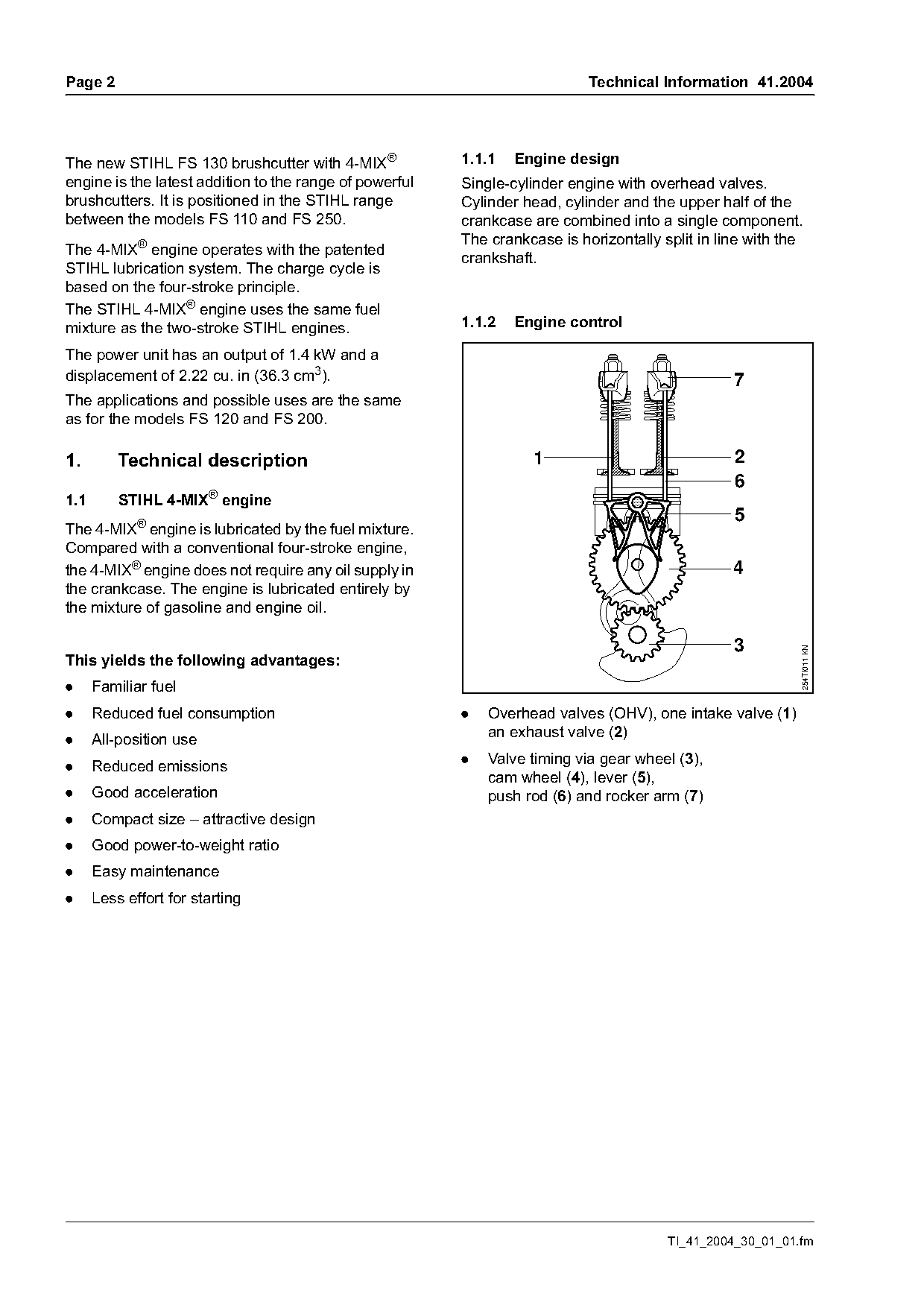
mixture as the two-stroke STIHL engines.                 1.1.2   Engine control

The power unit has an output of 1.4 kW and a
displacement of 2.22 cu. in (36.3 cm3).                                                           7
The applications and possible uses are the same
as for the models FS 120 and FS 200.

1.        Technical description                                    1                              2
                                                                                                  6
1.1       STIHL 4-MIX® engine
                                                                                                  5
The 4-MIX® engine is lubricated by the fuel mixture.
Compared with a conventional four-stroke engine,
the 4-MIX® engine does not require any oil supply in                                              4
the crankcase. The engine is lubricated entirely by
the mixture of gasoline and engine oil.


                                                                                                            254TI011 KN
This yields the following advantages:
.     Familiar fuel
.     Reduced fuel consumption                           .   Overhead valves (OHV), one intake valve (1)
.     All-position use                                       an exhaust valve (2)

.     Reduced emissions                                  .   Valve timing via gear wheel (3),
                                                             cam wheel (4), lever (5),
.     Good acceleration                                      push rod (6) and rocker arm (7)
.     Compact size – attractive design
.     Good power-to-weight ratio
.     Easy maintenance
.     Less effort for starting

                                                                                        TI_41_2004_30_01_01.fm
Page 3 of 10
Text of page 3 — search, copy, screen readers
Technical Information 41.2004                                                                       Page 3

1.2     Filler cap                                 2.2     Ignition system
                                                   Ignition module:           With integrated
                                                                              electronic speed
                                                                              governor
                                                   Spark plug                 NGK CMR 6 H
                                                   (suppressed):
                                                   Electrode gap:             0.028 in (0.7 mm)

                                                   2.3     Fuel system
                                                   The STIHL 4-MIX® engine is mixture-lubricated and
                                                   must be operated with a mixture of gasoline and
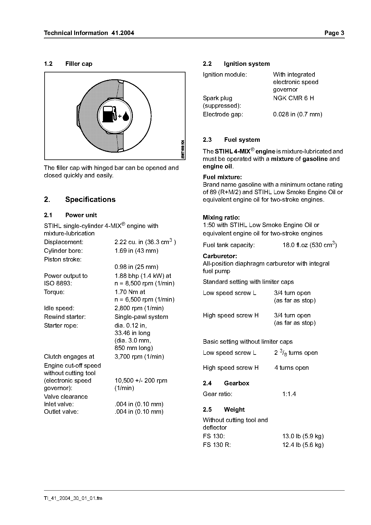
The filler cap with hinged bar can be opened and   engine oil.
closed quickly and easily.                         Fuel mixture:
                                                   Brand name gasoline with a minimum octane rating
                                                   of 89 (R+M/2) and STIHL Low Smoke Engine Oil or
2.     Specifications                              equivalent engine oil for two-stroke engines.

2.1     Power unit                                 Mixing ratio:
STIHL single-cylinder 4-MIX® engine with           1:50 with STIHL Low Smoke Engine Oil or
mixture-lubrication                                equivalent engine oil for two-stroke engines
Displacement:            2.22 cu. in (36.3 cm3 )   Fuel tank capacity:           18.0 fl.oz (530 cm3)
Cylinder bore:           1.69 in (43 mm)
                                                   Carburetor:
Piston stroke:
                                                   All-position diaphragm carburetor with integral
                         0.98 in (25 mm)
                                                   fuel pump
Power output to          1.88 bhp (1.4 kW) at
ISO 8893:                n = 8,500 rpm (1/min)     Standard setting with limiter caps
Torque:                  1.70 Nm at                Low speed screw L          3/4 turn open
                         n = 6,500 rpm (1/min)                                (as far as stop)
Idle speed:              2,800 rpm (1/min)
Rewind starter:          Single-pawl system        High speed screw H         3/4 turn open
Starter rope:            dia. 0.12 in,                                        (as far as stop)
                         33.46 in long
                         (dia. 3.0 mm,             Basic setting without limiter caps
                         850 mm long)
                                                   Low speed screw L          2 3/8 turns open
Clutch engages at        3,700 rpm (1/min)
Engine cut-off speed                               High speed screw H         4 turns open
without cutting tool
(electronic speed        10,500 +/- 200 rpm        2.4     Gearbox
governor):               (1/min)
Valve clearance                                    Gear ratio:                   1:1.4
Inlet valve:             .004 in (0.10 mm)
Outlet valve:            .004 in (0.10 mm)         2.5     Weight
                                                   Without cutting tool and
                                                   deflector
                                                   FS 130:                       13.0 lb (5.9 kg)
                                                   FS 130 R:                     12.4 lb (5.6 kg)

TI_41_2004_30_01_01.fm
Page 4 of 10
Text of page 4 — search, copy, screen readers
Page 4                                                                Technical Information 41.2004

3.       Cutting tools
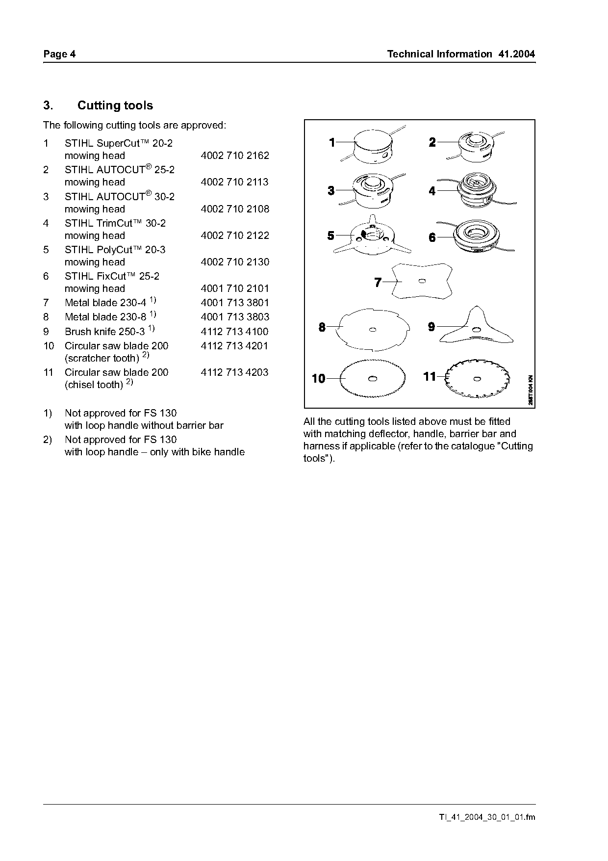
The following cutting tools are approved:
1    STIHL SuperCut™ 20-2
     mowing head                   4002 710 2162
2    STIHL AUTOCUT® 25-2
     mowing head                   4002 710 2113
3    STIHL AUTOCUT® 30-2
     mowing head                   4002 710 2108
4    STIHL TrimCut™ 30-2
     mowing head                   4002 710 2122
5    STIHL PolyCut™ 20-3
     mowing head                   4002 710 2130
6    STIHL FixCut™ 25-2
     mowing head                   4001 710 2101
7    Metal blade 230-4 1)          4001 713 3801
8    Metal blade 230-8 1)          4001 713 3803
9    Brush knife 250-3 1)          4112 713 4100
10   Circular saw blade 200        4112 713 4201
     (scratcher tooth) 2)
11   Circular saw blade 200        4112 713 4203
     (chisel tooth) 2)

1)   Not approved for FS 130
     with loop handle without barrier bar          All the cutting tools listed above must be fitted
                                                   with matching deflector, handle, barrier bar and
2)   Not approved for FS 130
                                                   harness if applicable (refer to the catalogue "Cutting
     with loop handle – only with bike handle
                                                   tools").

                                                                                  TI_41_2004_30_01_01.fm
Page 5 of 10
Text of page 5 — search, copy, screen readers
Technical Information 41.2004                                                                       Page 5

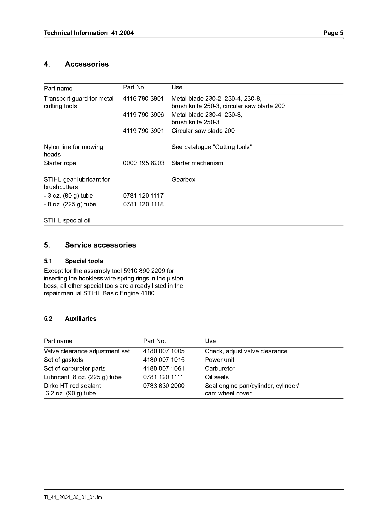
4.      Accessories

Part name                      Part No.           Use
Transport guard for metal      4116 790 3901      Metal blade 230-2, 230-4, 230-8,
cutting tools                                     brush knife 250-3, circular saw blade 200
                               4119 790 3906      Metal blade 230-4, 230-8,
                                                  brush knife 250-3
                               4119 790 3901      Circular saw blade 200

Nylon line for mowing                             See catalogue "Cutting tools"
heads
Starter rope                   0000 195 8203      Starter mechanism

STIHL gear lubricant for                          Gearbox
brushcutters
- 3 oz. (80 g) tube            0781 120 1117
- 8 oz. (225 g) tube           0781 120 1118

STIHL special oil

5.      Service accessories

5.1     Special tools
Except for the assembly tool 5910 890 2209 for
inserting the hookless wire spring rings in the piston
boss, all other special tools are already listed in the
repair manual STIHL Basic Engine 4180.

5.2     Auxiliaries

Part name                              Part No.               Use
Valve clearance adjustment set         4180 007 1005          Check, adjust valve clearance
Set of gaskets                         4180 007 1015          Power unit
Set of carburetor parts                4180 007 1061          Carburetor
Lubricant 8 oz. (225 g) tube           0781 120 1111          Oil seals
Dirko HT red sealant                   0783 830 2000          Seal engine pan/cylinder, cylinder/
3.2 oz. (90 g) tube                                           cam wheel cover

TI_41_2004_30_01_01.fm
Page 6 of 10
Text of page 6 — search, copy, screen readers
Page 6                                                                                Technical Information 41.2004

6.       Service note                                              6.1.2   Function

The specific national safety regulations and the
safety instructions in the user manual must be
observed if the unit has to be started.

6.1      Carburetor
The carburetor is set to the standard setting by the
manufacturer.                                                          270°                                      270°
This carburetor setting ensures that the engine
receives an optimum mixture of fuel and air in all

                                                                                                                         249TI004 KN
operating states.
The high speed and low speed screws can only be
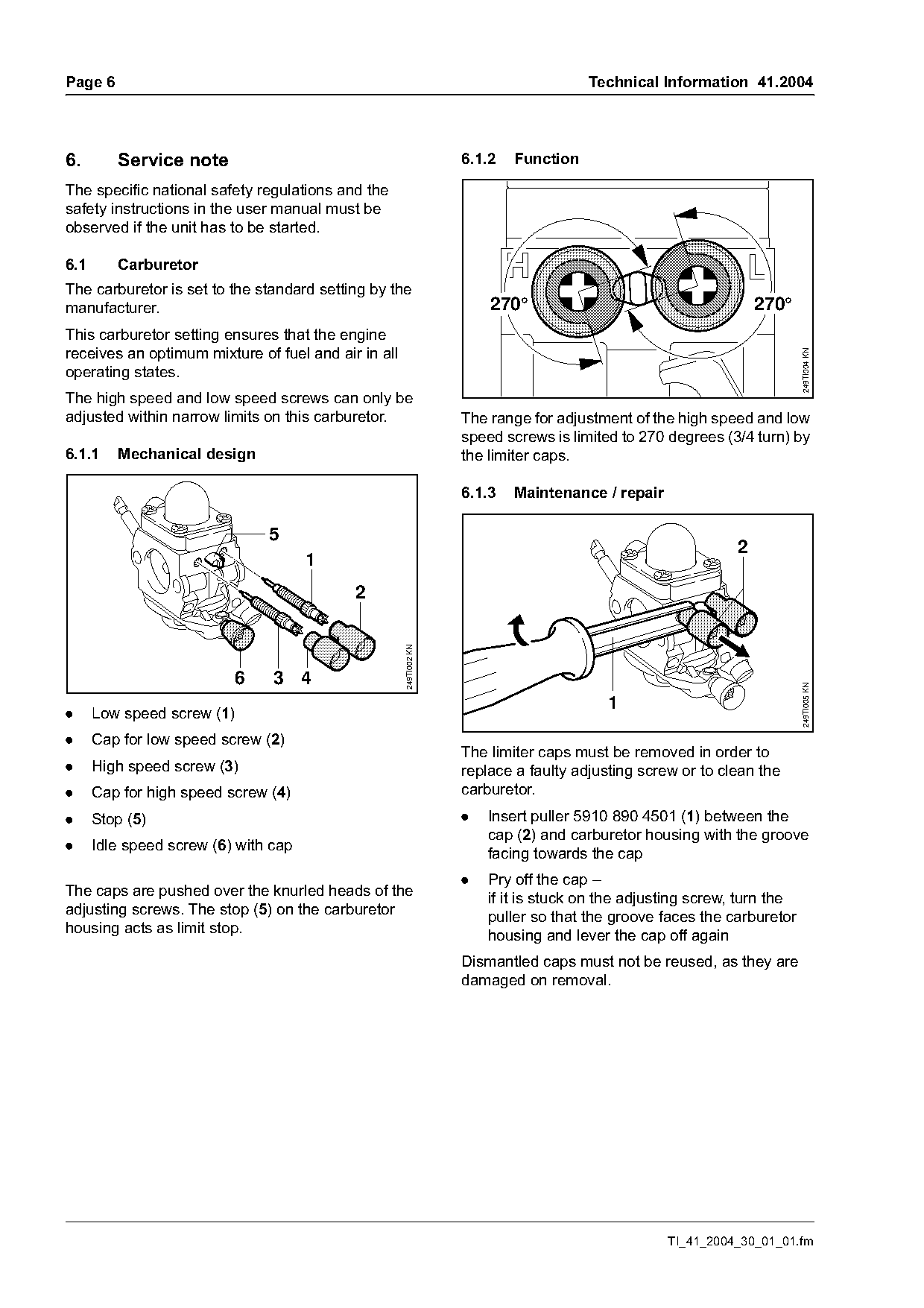
adjusted within narrow limits on this carburetor.                  The range for adjustment of the high speed and low
                                                                   speed screws is limited to 270 degrees (3/4 turn) by
6.1.1    Mechanical design                                         the limiter caps.

                                                                   6.1.3   Maintenance / repair

                               5
                                                                                                             2
                                      1
                                           2
                                                     249TI002 KN

                          6     3 4

                                                                                                                         249TI005 KN
                                                                                         1
.     Low speed screw (1)
.     Cap for low speed screw (2)
                                                                   The limiter caps must be removed in order to
.     High speed screw (3)                                         replace a faulty adjusting screw or to clean the
.     Cap for high speed screw (4)                                 carburetor.
.     Stop (5)                                                     .   Insert puller 5910 890 4501 (1) between the
                                                                       cap (2) and carburetor housing with the groove
.     Idle speed screw (6) with cap
                                                                       facing towards the cap
                                                                   .   Pry off the cap –
The caps are pushed over the knurled heads of the
                                                                       if it is stuck on the adjusting screw, turn the
adjusting screws. The stop (5) on the carburetor
                                                                       puller so that the groove faces the carburetor
housing acts as limit stop.
                                                                       housing and lever the cap off again
                                                                   Dismantled caps must not be reused, as they are
                                                                   damaged on removal.

                                                                                                  TI_41_2004_30_01_01.fm
Page 7 of 10
Text of page 7 — search, copy, screen readers
Technical Information 41.2004                                                                                     Page 7

Adjustment after maintenance / repair                              Set idle speed
.   Check air filter – clean or replace it if necessary
.   Check spark arresting screen (if fitted) –
    clean or replace it if necessary
                                                                           H               L
.   Check fuel filter-replace if necessary

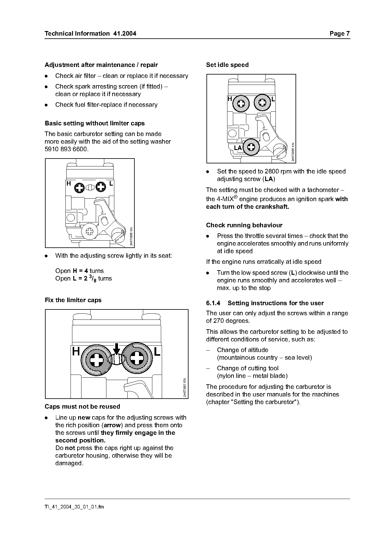
Basic setting without limiter caps
The basic carburetor setting can be made
more easily with the aid of the setting washer

                                                                                                    249TI009 KN
5910 893 6600.                                                                 LA

                                                                   .   Set the speed to 2800 rpm with the idle speed
                                                                       adjusting screw (LA)
        H                L
                                                                   The setting must be checked with a tachometer –
                                                                   the 4-MIX® engine produces an ignition spark with
                                                                   each turn of the crankshaft.

                                                                   Check running behaviour
                                249TI006 KN

                                                                   .   Press the throttle several times – check that the
                                                                       engine accelerates smoothly and runs uniformly
                                                                       at idle speed
.   With the adjusting screw lightly in its seat:
                                                                   If the engine runs erratically at idle speed
    Open H = 4 turns                                               .   Turn the low speed screw (L) clockwise until the
    Open L = 2 3/8 turns                                               engine runs smoothly and accelerates well –
                                                                       max. up to the stop
Fix the limiter caps                                               6.1.4   Setting instructions for the user
                                                                   The user can only adjust the screws within a range
                                                                   of 270 degrees.
                                                                   This allows the carburetor setting to be adjusted to
                                                                   different conditions of service, such as:
                                                                   –   Change of altitude
            H                                 L                        (mountainous country – sea level)
                                                                   –   Change of cutting tool
                                                                       (nylon line – metal blade)
                                                     249TI007 KN

                                                                   The procedure for adjusting the carburetor is
                                                                   described in the user manuals for the machines
                                                                   (chapter "Setting the carburetor").
Caps must not be reused
.   Line up new caps for the adjusting screws with
    the rich position (arrow) and press them onto
    the screws until they firmly engage in the
    second position.
    Do not press the caps right up against the
    carburetor housing, otherwise they will be
    damaged.

TI_41_2004_30_01_01.fm
Page 8 of 10
Text of page 8 — search, copy, screen readers
Page 8                                                Technical Information 41.2004

6.2      Inspect valve clearance
Valve clearance should be checked once after
approximately 140 hours of operation and adjusted
if necessary. The valve clearance should only be
checked and adjusted when the engine is cold. The
4180 007 1005 "Valve adjustment kit" with setting
gauge, sealing ring and gasket should be used for
this purpose.

6.3      Test for leaks
Defective oil gaskets and O-rings or cracks in the
cast parts cause air leaks.
The power unit can be tested for leaks with the aid
of the carburetor / crankcase pressure tester and
the vacuum pump.
Proceed as described for the model FS 110
(see TI 03.2003) when testing for leaks.

                                                                TI_41_2004_30_01_01.fm
Page 9 of 10
Text of page 9 — search, copy, screen readers
Technical Information 41.2004                                                                       Page 9

6.4   Tightening torques
Tightening torques for the FS 130 are listed in the    Code Repair procedure                      FS 130
repair manual STIHL Basic Engine 4180.                 1    Crankcase, crankshaft, bearing          1.5
                                                       2
6.5   Service note
                                                       3    Crankcase sealing, leakage test         1.3
The repair manual STIHL Basic Engine 4180 is
                                                       4    Oil gaskets (crankcase)
available for servicing and repairing the STIHL
                                                            (including leakage test)                0.9
FS 130; refer also to the STIHL Service Training
System "Diagnosis".                                    5    Cylinder and/or piston,                 1.8
                                                            replace valves
6.6   Repair times                                     6    Ignition module                         0.4
The specified repair times assume that the work        7    Fuel supply                             0.4
is performed by trained personnel in a properly        8    Replace gear box,
equipped service workshop.                                  bearing housing                         0.4
                                                       9    Repair carburetor                       0.7
Repair times are stated in tenths of an hour
(0.1 = 6 minutes).                                    10    Replace carburetor/nozzles
                                                            (use code 9 for attempted
The table of repair times for FS 130 can be added           repair)                                 0.4
to the table of STIHL repair times.
                                                      11    Handle and throttle control             0.4
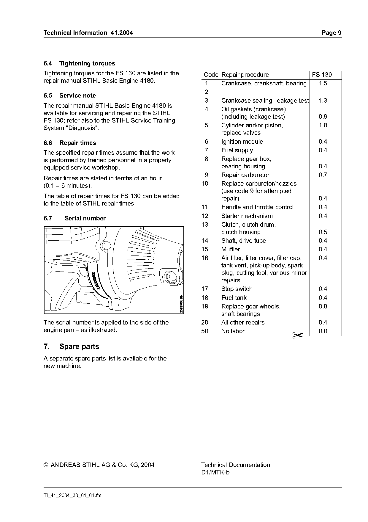
6.7     Serial number                                 12    Starter mechanism                       0.4
                                                      13    Clutch, clutch drum,
                                                            clutch housing                          0.5
                                                      14    Shaft, drive tube                       0.4
                                                      15    Muffler                                 0.4
                                                      16    Air filter, filter cover, filler cap,   0.4
                                                            tank vent, pick-up body, spark
                                                            plug, cutting tool, various minor
                                                            repairs
                                                      17    Stop switch                             0.4
                                                      18    Fuel tank                               0.4
                                                      19    Replace gear wheels,                    0.8
                                                            shaft bearings
The serial number is applied to the side of the       20    All other repairs                       0.4
engine pan – as illustrated.                          50    No labor                                0.0
7.    Spare parts
A separate spare parts list is available for the
new machine.

© ANDREAS STIHL AG & Co. KG, 2004                     Technical Documentation
                                                      D1/MTK-bl

TI_41_2004_30_01_01.fm
Page 10 of 10

Text of page 10 — search, copy, screen readers
Page 10   Technical Information 41.2004

                    TI_41_2004_30_01_01.fm
Most of these PDFs embed fonts with a shifted character map, so the text above was recovered rather than copied — read it as a faithful but imperfect transcription, and treat the page image above each block as the authority where the two disagree — the figures exist only there, because they are vector drawings that text extraction cannot keep.