Technical Information · issue 47 of 2004
STIHL Special tool panels
IssueTI 47/2004
Full text
Page 1 of 8
Text of page 1 — search, copy, screen readers
STIH)

Technical Information                              47.2004

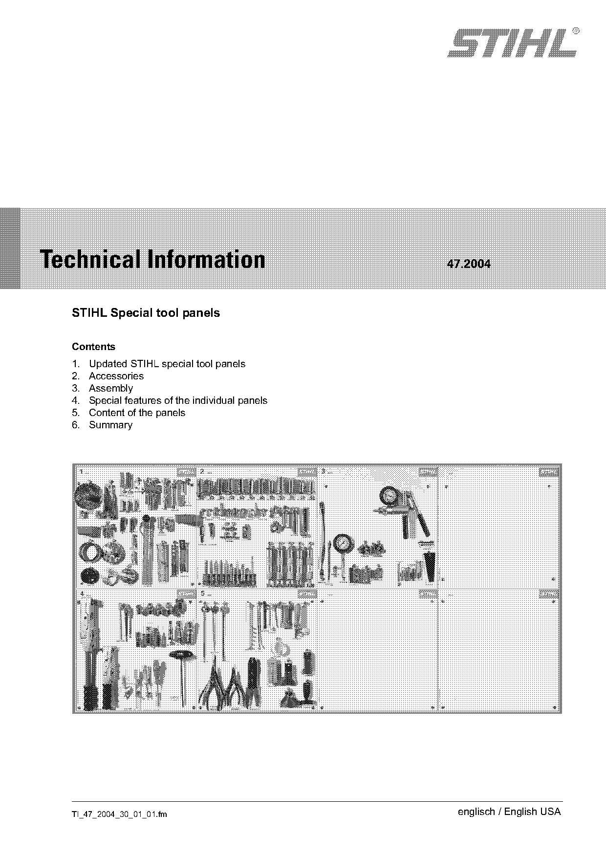
  STIHL Special tool panels

  Contents
  1.   Updated STIHL special tool panels
  2.   Accessories
  3.   Assembly
  4.   Special features of the individual panels
  5.   Content of the panels
  6.   Summary

  TI_47_2004_30_01_01.fm                            englisch / English USA
Page 2 of 8
Text of page 2 — search, copy, screen readers
Page 2                                                                      Technical Information 47.2004

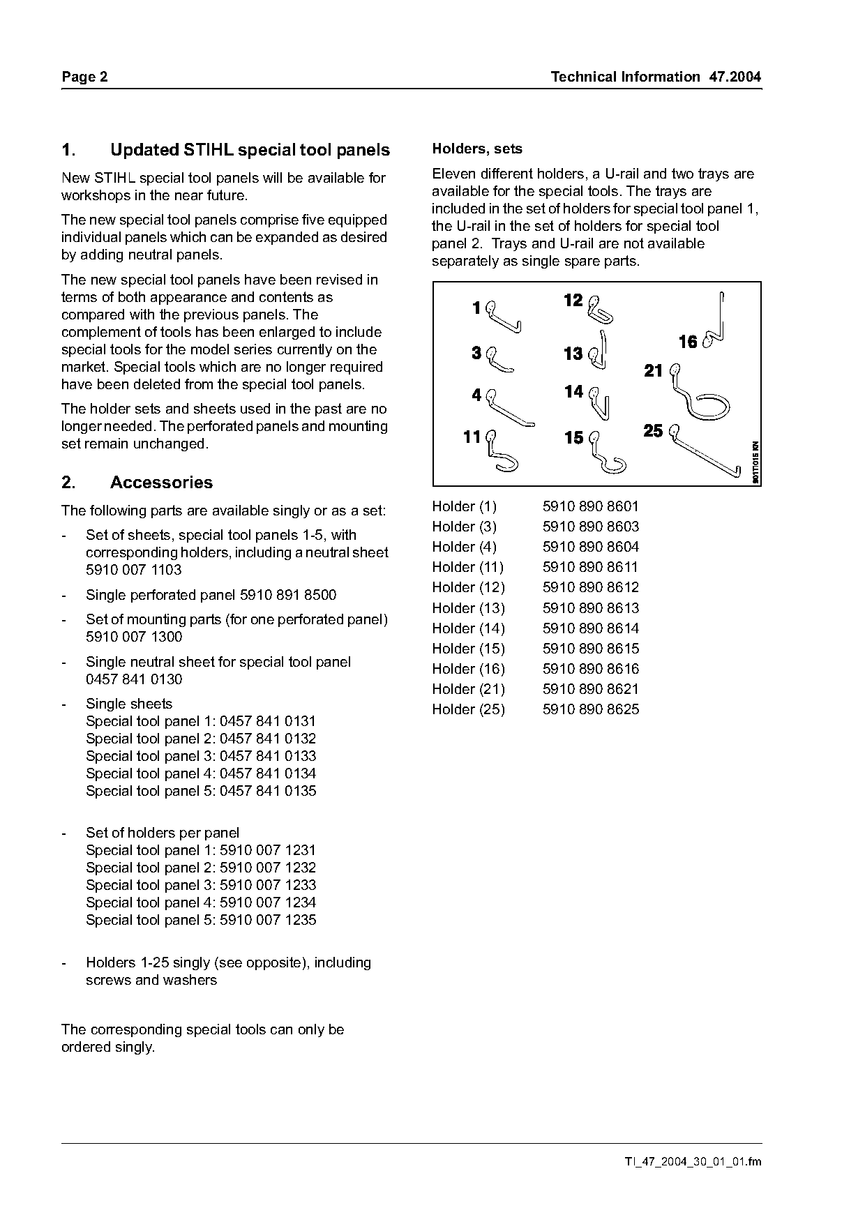
1.       Updated STIHL special tool panels              Holders, sets

New STIHL special tool panels will be available for     Eleven different holders, a U-rail and two trays are
workshops in the near future.                           available for the special tools. The trays are
                                                        included in the set of holders for special tool panel 1,
The new special tool panels comprise five equipped      the U-rail in the set of holders for special tool
individual panels which can be expanded as desired      panel 2. Trays and U-rail are not available
by adding neutral panels.                               separately as single spare parts.
The new special tool panels have been revised in
terms of both appearance and contents as
compared with the previous panels. The
complement of tools has been enlarged to include
special tools for the model series currently on the
market. Special tools which are no longer required
have been deleted from the special tool panels.
The holder sets and sheets used in the past are no
longer needed. The perforated panels and mounting
set remain unchanged.

2.       Accessories
The following parts are available singly or as a set:   Holder (1)        5910 890 8601
                                                        Holder (3)        5910 890 8603
-    Set of sheets, special tool panels 1-5, with
     corresponding holders, including a neutral sheet   Holder (4)        5910 890 8604
     5910 007 1103                                      Holder (11)       5910 890 8611
-    Single perforated panel 5910 891 8500              Holder (12)       5910 890 8612
                                                        Holder (13)       5910 890 8613
-    Set of mounting parts (for one perforated panel)
                                                        Holder (14)       5910 890 8614
     5910 007 1300
                                                        Holder (15)       5910 890 8615
-    Single neutral sheet for special tool panel
                                                        Holder (16)       5910 890 8616
     0457 841 0130
                                                        Holder (21)       5910 890 8621
-    Single sheets                                      Holder (25)       5910 890 8625
     Special tool panel 1: 0457 841 0131
     Special tool panel 2: 0457 841 0132
     Special tool panel 3: 0457 841 0133
     Special tool panel 4: 0457 841 0134
     Special tool panel 5: 0457 841 0135

-    Set of holders per panel
     Special tool panel 1: 5910 007 1231
     Special tool panel 2: 5910 007 1232
     Special tool panel 3: 5910 007 1233
     Special tool panel 4: 5910 007 1234
     Special tool panel 5: 5910 007 1235

-    Holders 1-25 singly (see opposite), including
     screws and washers

The corresponding special tools can only be
ordered singly.

                                                                                         TI_47_2004_30_01_01.fm
Page 3 of 8
Text of page 3 — search, copy, screen readers
Technical Information 47.2004                                                                           Page 3

3.       Assembly

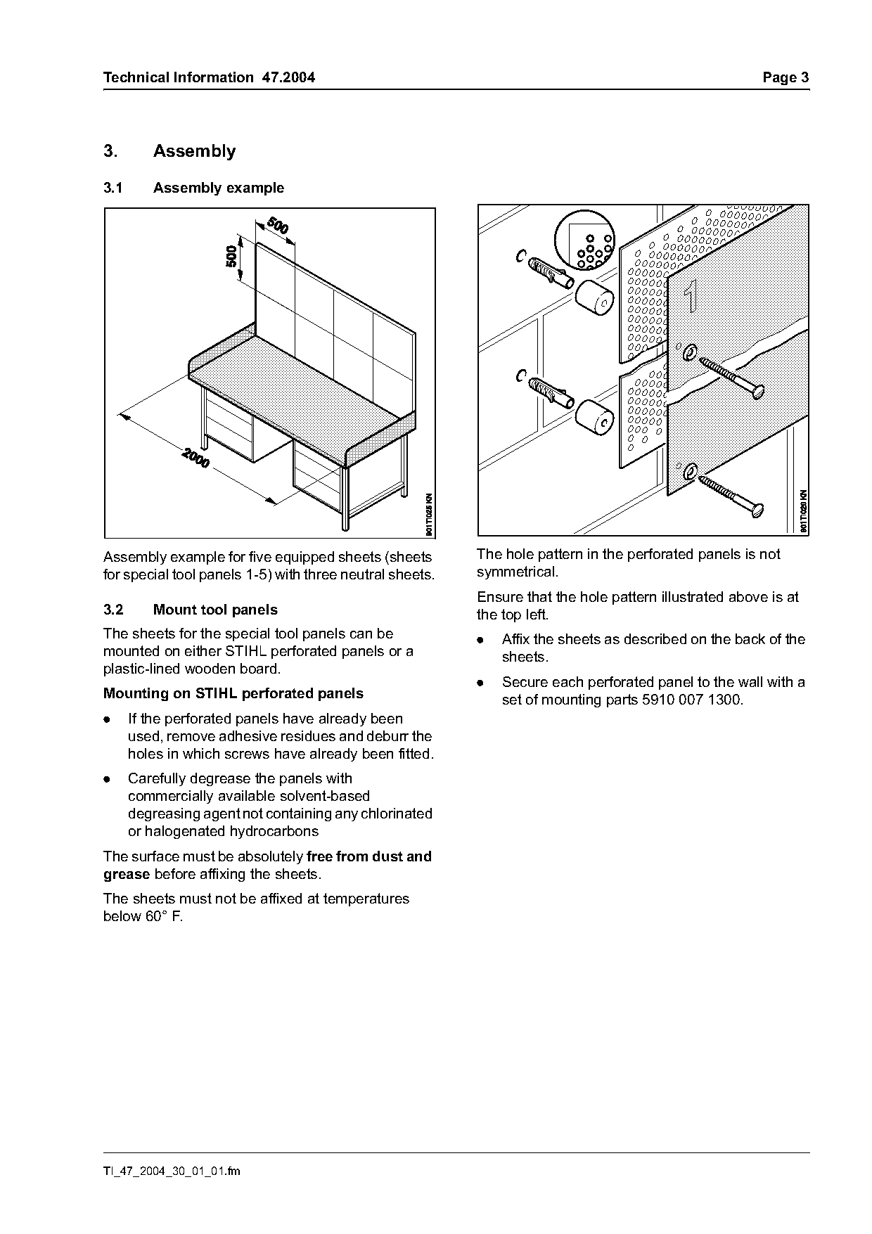
3.1      Assembly example

Assembly example for five equipped sheets (sheets         The hole pattern in the perforated panels is not
for special tool panels 1-5) with three neutral sheets.   symmetrical.
                                                          Ensure that the hole pattern illustrated above is at
3.2      Mount tool panels                                the top left.
The sheets for the special tool panels can be             .   Affix the sheets as described on the back of the
mounted on either STIHL perforated panels or a                sheets.
plastic-lined wooden board.
                                                          .   Secure each perforated panel to the wall with a
Mounting on STIHL perforated panels                           set of mounting parts 5910 007 1300.
.     If the perforated panels have already been
      used, remove adhesive residues and deburr the
      holes in which screws have already been fitted.
.     Carefully degrease the panels with
      commercially available solvent-based
      degreasing agent not containing any chlorinated
      or halogenated hydrocarbons
The surface must be absolutely free from dust and
grease before affixing the sheets.
The sheets must not be affixed at temperatures
below 60° F.

TI_47_2004_30_01_01.fm
Page 4 of 8
Text of page 4 — search, copy, screen readers
Page 4                                                                          Technical Information 47.2004

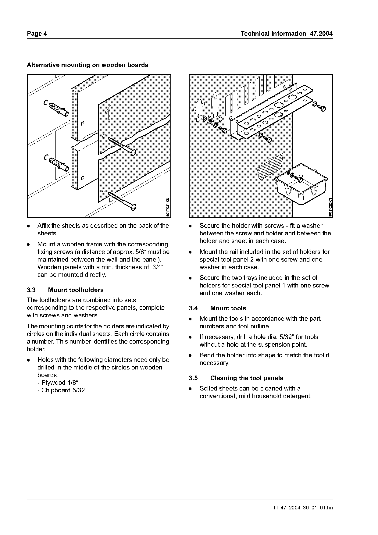
Alternative mounting on wooden boards

.     Affix the sheets as described on the back of the    .     Secure the holder with screws - fit a washer
      sheets.                                                   between the screw and holder and between the
                                                                holder and sheet in each case.
.     Mount a wooden frame with the corresponding
      fixing screws (a distance of approx. 5/8“ must be   .     Mount the rail included in the set of holders for
      maintained between the wall and the panel).               special tool panel 2 with one screw and one
      Wooden panels with a min. thickness of 3/4“               washer in each case.
      can be mounted directly.                            .     Secure the two trays included in the set of
                                                                holders for special tool panel 1 with one screw
3.3      Mount toolholders
                                                                and one washer each.
The toolholders are combined into sets
corresponding to the respective panels, complete          3.4       Mount tools
with screws and washers.
                                                          .     Mount the tools in accordance with the part
The mounting points for the holders are indicated by            numbers and tool outline.
circles on the individual sheets. Each circle contains
                                                          .     If necessary, drill a hole dia. 5/32“ for tools
a number. This number identifies the corresponding
                                                                without a hole at the suspension point.
holder.
                                                          .     Bend the holder into shape to match the tool if
.     Holes with the following diameters need only be           necessary.
      drilled in the middle of the circles on wooden
      boards:                                             3.5       Cleaning the tool panels
      - Plywood 1/8“
      - Chipboard 5/32“                                   .     Soiled sheets can be cleaned with a
                                                                conventional, mild household detergent.

                                                                                             TI_47_2004_30_01_01.fm
Page 5 of 8
Text of page 5 — search, copy, screen readers
Technical Information 47.2004                                                               Page 5

4.      Special features of the individual           5910 890 2000   Tensioning bar
        panels                                       5910 890 2202   Assembly tool
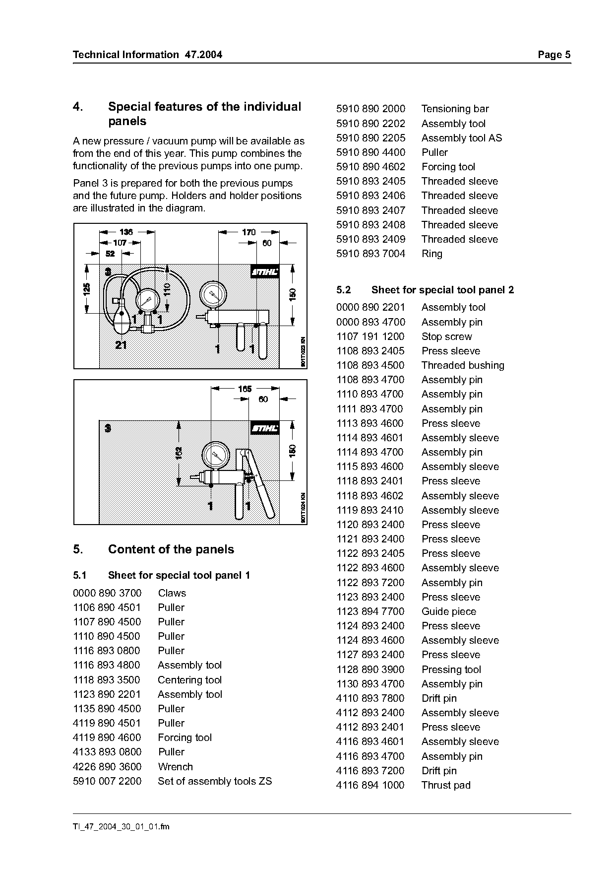
A new pressure / vacuum pump will be available as    5910 890 2205   Assembly tool AS
from the end of this year. This pump combines the    5910 890 4400   Puller
functionality of the previous pumps into one pump.   5910 890 4602   Forcing tool
Panel 3 is prepared for both the previous pumps      5910 893 2405   Threaded sleeve
and the future pump. Holders and holder positions    5910 893 2406   Threaded sleeve
are illustrated in the diagram.                      5910 893 2407   Threaded sleeve
                                                     5910 893 2408   Threaded sleeve
                                                     5910 893 2409   Threaded sleeve
                                                     5910 893 7004   Ring

                                                     5.2   Sheet for special tool panel 2
                                                     0000 890 2201   Assembly tool
                                                     0000 893 4700   Assembly pin
                                                     1107 191 1200   Stop screw
                                                     1108 893 2405   Press sleeve
                                                     1108 893 4500   Threaded bushing
                                                     1108 893 4700   Assembly pin
                                                     1110 893 4700   Assembly pin
                                                     1111 893 4700   Assembly pin
                                                     1113 893 4600   Press sleeve
                                                     1114 893 4601   Assembly sleeve
                                                     1114 893 4700   Assembly pin
                                                     1115 893 4600   Assembly sleeve
                                                     1118 893 2401   Press sleeve
                                                     1118 893 4602   Assembly sleeve
                                                     1119 893 2410   Assembly sleeve
                                                     1120 893 2400   Press sleeve
                                                     1121 893 2400   Press sleeve
5.     Content of the panels                         1122 893 2405   Press sleeve
                                                     1122 893 4600   Assembly sleeve
5.1     Sheet for special tool panel 1
                                                     1122 893 7200   Assembly pin
0000 890 3700      Claws                             1123 893 2400   Press sleeve
1106 890 4501      Puller                            1123 894 7700   Guide piece
1107 890 4500      Puller                            1124 893 2400   Press sleeve
1110 890 4500      Puller                            1124 893 4600   Assembly sleeve
1116 893 0800      Puller                            1127 893 2400   Press sleeve
1116 893 4800      Assembly tool                     1128 890 3900   Pressing tool
1118 893 3500      Centering tool                    1130 893 4700   Assembly pin
1123 890 2201      Assembly tool                     4110 893 7800   Drift pin
1135 890 4500      Puller                            4112 893 2400   Assembly sleeve
4119 890 4501      Puller                            4112 893 2401   Press sleeve
4119 890 4600      Forcing tool                      4116 893 4601   Assembly sleeve
4133 893 0800      Puller                            4116 893 4700   Assembly pin
4226 890 3600      Wrench                            4116 893 7200   Drift pin
5910 007 2200      Set of assembly tools ZS          4116 894 1000   Thrust pad

TI_47_2004_30_01_01.fm
Page 6 of 8
Text of page 6 — search, copy, screen readers
Page 6                                                            Technical Information 47.2004

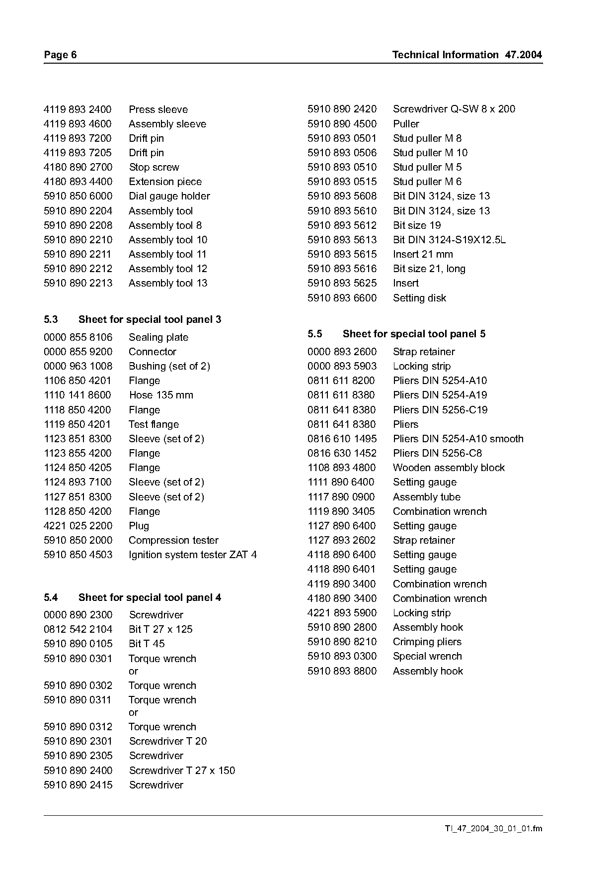
4119 893 2400      Press sleeve                   5910 890 2420   Screwdriver Q-SW 8 x 200
4119 893 4600      Assembly sleeve                5910 890 4500   Puller
4119 893 7200      Drift pin                      5910 893 0501   Stud puller M 8
4119 893 7205      Drift pin                      5910 893 0506   Stud puller M 10
4180 890 2700      Stop screw                     5910 893 0510   Stud puller M 5
4180 893 4400      Extension piece                5910 893 0515   Stud puller M 6
5910 850 6000      Dial gauge holder              5910 893 5608   Bit DIN 3124, size 13
5910 890 2204      Assembly tool                  5910 893 5610   Bit DIN 3124, size 13
5910 890 2208      Assembly tool 8                5910 893 5612   Bit size 19
5910 890 2210      Assembly tool 10               5910 893 5613   Bit DIN 3124-S19X12.5L
5910 890 2211      Assembly tool 11               5910 893 5615   Insert 21 mm
5910 890 2212      Assembly tool 12               5910 893 5616   Bit size 21, long
5910 890 2213      Assembly tool 13               5910 893 5625   Insert
                                                  5910 893 6600   Setting disk

5.3      Sheet for special tool panel 3
0000 855 8106      Sealing plate                  5.5   Sheet for special tool panel 5
0000 855 9200      Connector                      0000 893 2600   Strap retainer
0000 963 1008      Bushing (set of 2)             0000 893 5903   Locking strip
1106 850 4201      Flange                         0811 611 8200   Pliers DIN 5254-A10
1110 141 8600      Hose 135 mm                    0811 611 8380   Pliers DIN 5254-A19
1118 850 4200      Flange                         0811 641 8380   Pliers DIN 5256-C19
1119 850 4201      Test flange                    0811 641 8380   Pliers
1123 851 8300      Sleeve (set of 2)              0816 610 1495   Pliers DIN 5254-A10 smooth
1123 855 4200      Flange                         0816 630 1452   Pliers DIN 5256-C8
1124 850 4205      Flange                         1108 893 4800   Wooden assembly block
1124 893 7100      Sleeve (set of 2)              1111 890 6400   Setting gauge
1127 851 8300      Sleeve (set of 2)              1117 890 0900   Assembly tube
1128 850 4200      Flange                         1119 890 3405   Combination wrench
4221 025 2200      Plug                           1127 890 6400   Setting gauge
5910 850 2000      Compression tester             1127 893 2602   Strap retainer
5910 850 4503      Ignition system tester ZAT 4   4118 890 6400   Setting gauge
                                                  4118 890 6401   Setting gauge
                                                  4119 890 3400   Combination wrench
5.4      Sheet for special tool panel 4           4180 890 3400   Combination wrench
0000 890 2300      Screwdriver                    4221 893 5900   Locking strip
0812 542 2104      Bit T 27 x 125                 5910 890 2800   Assembly hook
5910 890 0105      Bit T 45                       5910 890 8210   Crimping pliers
5910 890 0301      Torque wrench                  5910 893 0300   Special wrench
                   or                             5910 893 8800   Assembly hook
5910 890 0302      Torque wrench
5910 890 0311      Torque wrench
5910 890 0312      Torque wrench
5910 890 2301      Screwdriver T 20
5910 890 2305      Screwdriver
5910 890 2400      Screwdriver T 27 x 150
5910 890 2415      Screwdriver

                                                                             TI_47_2004_30_01_01.fm
Page 7 of 8
Text of page 7 — search, copy, screen readers
Technical Information 47.2004                                                           Page 7

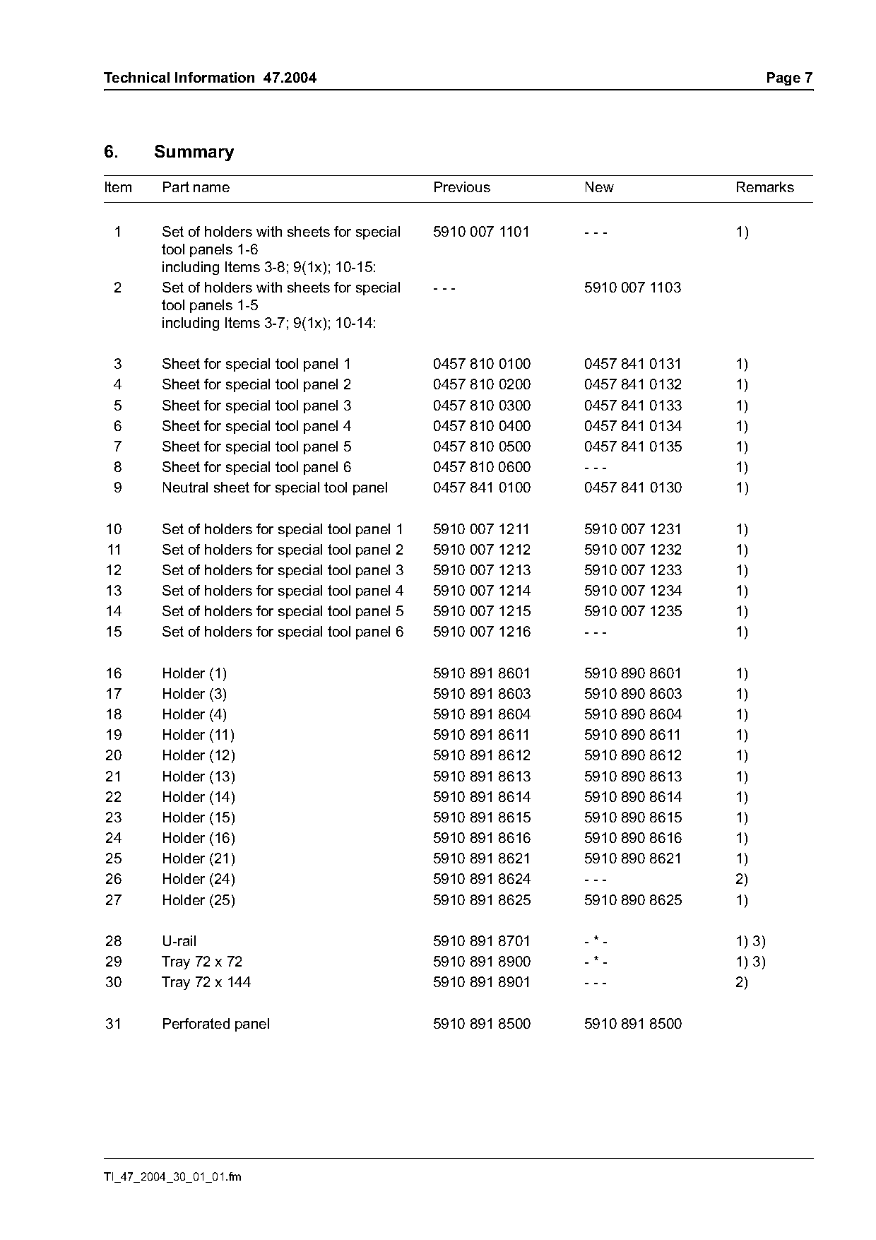
6.     Summary
Item     Part name                                 Previous        New             Remarks

 1       Set of holders with sheets for special    5910 007 1101   ---             1)
         tool panels 1-6
         including Items 3-8; 9(1x); 10-15:
 2       Set of holders with sheets for special    ---             5910 007 1103
         tool panels 1-5
         including Items 3-7; 9(1x); 10-14:

 3       Sheet for special tool panel 1            0457 810 0100   0457 841 0131   1)
 4       Sheet for special tool panel 2            0457 810 0200   0457 841 0132   1)
 5       Sheet for special tool panel 3            0457 810 0300   0457 841 0133   1)
 6       Sheet for special tool panel 4            0457 810 0400   0457 841 0134   1)
 7       Sheet for special tool panel 5            0457 810 0500   0457 841 0135   1)
 8       Sheet for special tool panel 6            0457 810 0600   ---             1)
 9       Neutral sheet for special tool panel      0457 841 0100   0457 841 0130   1)

10       Set of holders for special tool panel 1   5910 007 1211   5910 007 1231   1)
11       Set of holders for special tool panel 2   5910 007 1212   5910 007 1232   1)
12       Set of holders for special tool panel 3   5910 007 1213   5910 007 1233   1)
13       Set of holders for special tool panel 4   5910 007 1214   5910 007 1234   1)
14       Set of holders for special tool panel 5   5910 007 1215   5910 007 1235   1)
15       Set of holders for special tool panel 6   5910 007 1216   ---             1)

16       Holder (1)                                5910 891 8601   5910 890 8601   1)
17       Holder (3)                                5910 891 8603   5910 890 8603   1)
18       Holder (4)                                5910 891 8604   5910 890 8604   1)
19       Holder (11)                               5910 891 8611   5910 890 8611   1)
20       Holder (12)                               5910 891 8612   5910 890 8612   1)
21       Holder (13)                               5910 891 8613   5910 890 8613   1)
22       Holder (14)                               5910 891 8614   5910 890 8614   1)
23       Holder (15)                               5910 891 8615   5910 890 8615   1)
24       Holder (16)                               5910 891 8616   5910 890 8616   1)
25       Holder (21)                               5910 891 8621   5910 890 8621   1)
26       Holder (24)                               5910 891 8624   ---             2)
27       Holder (25)                               5910 891 8625   5910 890 8625   1)

28       U-rail                                    5910 891 8701   -*-             1) 3)
29       Tray 72 x 72                              5910 891 8900   -*-             1) 3)
30       Tray 72 x 144                             5910 891 8901   ---             2)

31       Perforated panel                          5910 891 8500   5910 891 8500

TI_47_2004_30_01_01.fm
Page 8 of 8
Text of page 8 — search, copy, screen readers
Page 8                                                                           Technical Information 47.2004

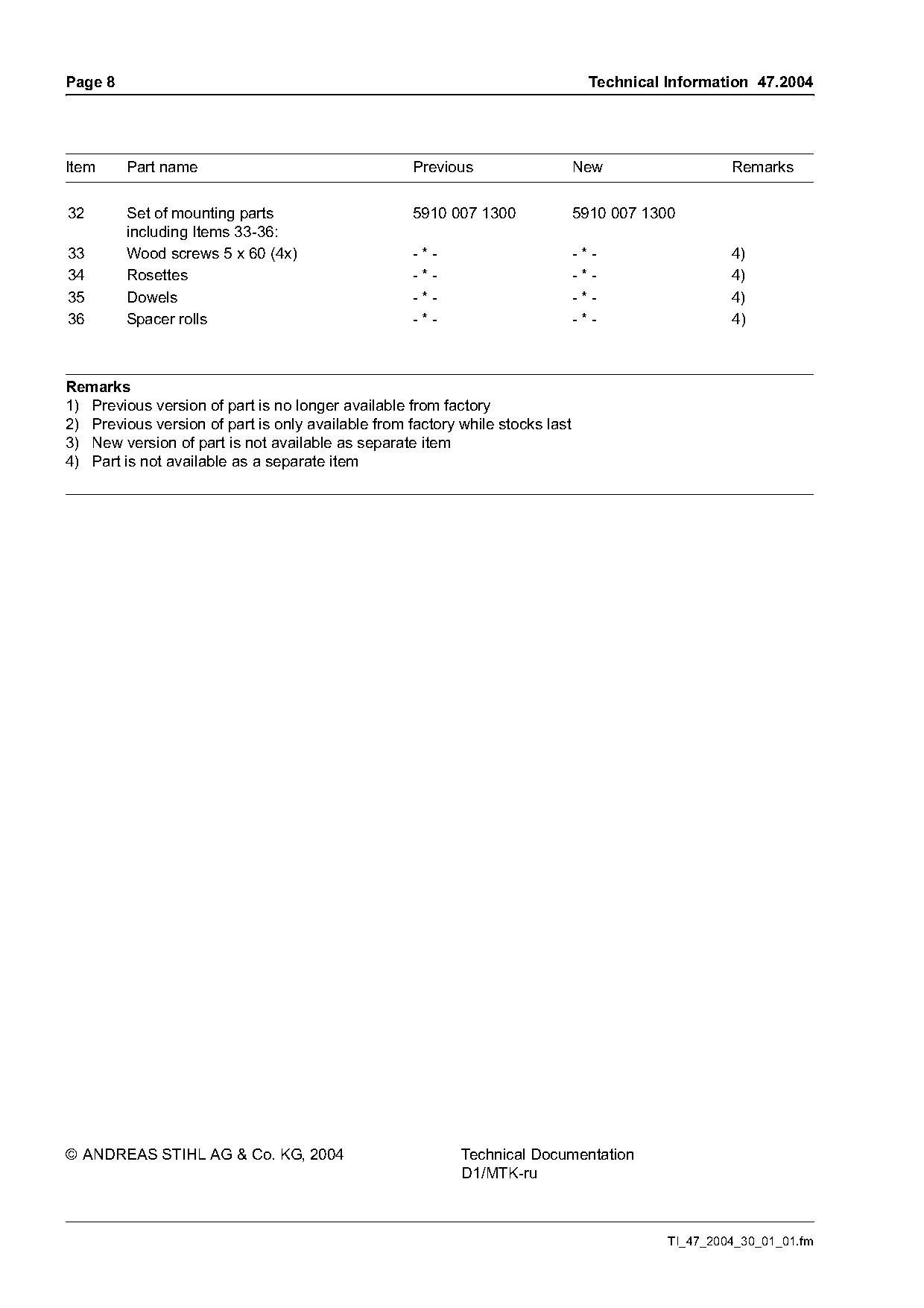
Item     Part name                                  Previous                   New                  Remarks

32       Set of mounting parts                      5910 007 1300              5910 007 1300
         including Items 33-36:
33       Wood screws 5 x 60 (4x)                    -*-                        -*-                  4)
34       Rosettes                                   -*-                        -*-                  4)
35       Dowels                                     -*-                        -*-                  4)
36       Spacer rolls                               -*-                        -*-                  4)

Remarks
1) Previous version of part is no longer available from factory
2) Previous version of part is only available from factory while stocks last
3) New version of part is not available as separate item
4) Part is not available as a separate item

© ANDREAS STIHL AG & Co. KG, 2004                          Technical Documentation
                                                           D1/MTK-ru

                                                                                           TI_47_2004_30_01_01.fm
Most of these PDFs embed fonts with a shifted character map, so the text above was recovered rather than copied — read it as a faithful but imperfect transcription, and treat the page image above each block as the authority where the two disagree — the figures exist only there, because they are vector drawings that text extraction cannot keep.