Technical Information · issue 49 of 2004
New brushcutter variant STIHL FS 100 RX
IssueTI 49/2004
Full text
Page 1 of 8
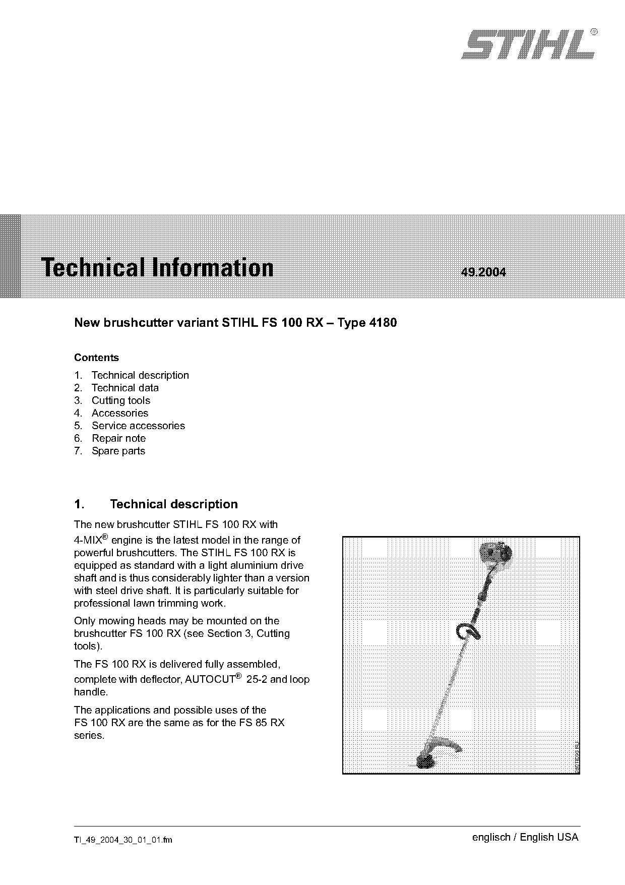
Text of page 1 — search, copy, screen readers
STIH)

Technical Information                                       49.2004

  New brushcutter variant STIHL FS 100 RX – Type 4180

  Contents
  1.   Technical description
  2.   Technical data
  3.   Cutting tools
  4.   Accessories
  5.   Service accessories
  6.   Repair note
  7.   Spare parts

  1.      Technical description
  The new brushcutter STIHL FS 100 RX with
  4-MIX® engine is the latest model in the range of
  powerful brushcutters. The STIHL FS 100 RX is
  equipped as standard with a light aluminium drive
  shaft and is thus considerably lighter than a version
  with steel drive shaft. It is particularly suitable for
  professional lawn trimming work.
  Only mowing heads may be mounted on the
  brushcutter FS 100 RX (see Section 3, Cutting
  tools).
  The FS 100 RX is delivered fully assembled,
  complete with deflector, AUTOCUT® 25-2 and loop
  handle.
  The applications and possible uses of the
  FS 100 RX are the same as for the FS 85 RX
  series.

  TI_49_2004_30_01_01.fm                                     englisch / English USA
Page 2 of 8
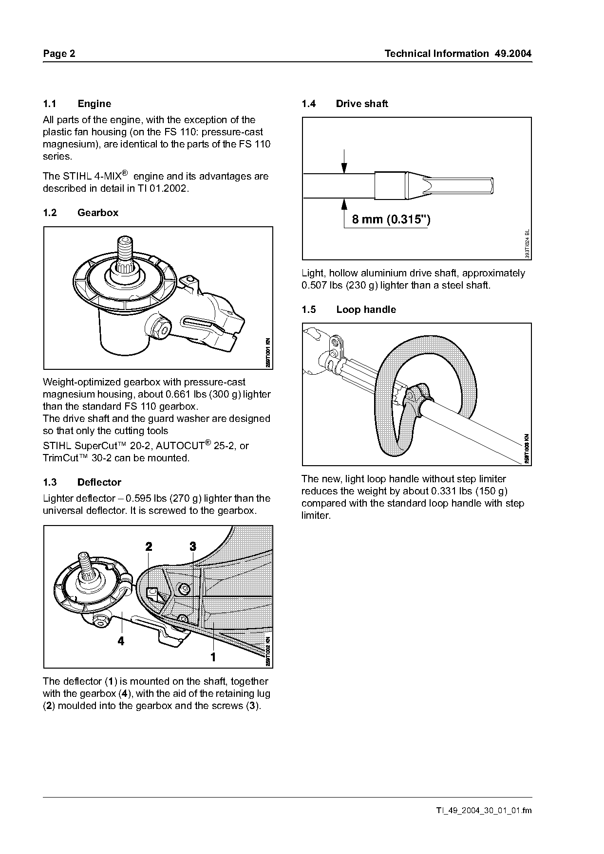
Text of page 2 — search, copy, screen readers
Page 2                                                                      Technical Information 49.2004

1.1      Engine                                           1.4    Drive shaft
All parts of the engine, with the exception of the
plastic fan housing (on the FS 110: pressure-cast
magnesium), are identical to the parts of the FS 110
series.
The STIHL 4-MIX® engine and its advantages are
described in detail in TI 01.2002.

1.2      Gearbox
                                                                     8 mm (0.315")

                                                                                                               393TI024 BL
                                                          Light, hollow aluminium drive shaft, approximately
                                                          0.507 lbs (230 g) lighter than a steel shaft.

                                                          1.5    Loop handle

Weight-optimized gearbox with pressure-cast
magnesium housing, about 0.661 lbs (300 g) lighter
than the standard FS 110 gearbox.
The drive shaft and the guard washer are designed
so that only the cutting tools
STIHL SuperCut™ 20-2, AUTOCUT® 25-2, or
TrimCut™ 30-2 can be mounted.

1.3      Deflector                                        The new, light loop handle without step limiter
                                                          reduces the weight by about 0.331 lbs (150 g)
Lighter deflector – 0.595 lbs (270 g) lighter than the    compared with the standard loop handle with step
universal deflector. It is screwed to the gearbox.        limiter.

The deflector (1) is mounted on the shaft, together
with the gearbox (4), with the aid of the retaining lug
(2) moulded into the gearbox and the screws (3).

                                                                                        TI_49_2004_30_01_01.fm
Page 3 of 8
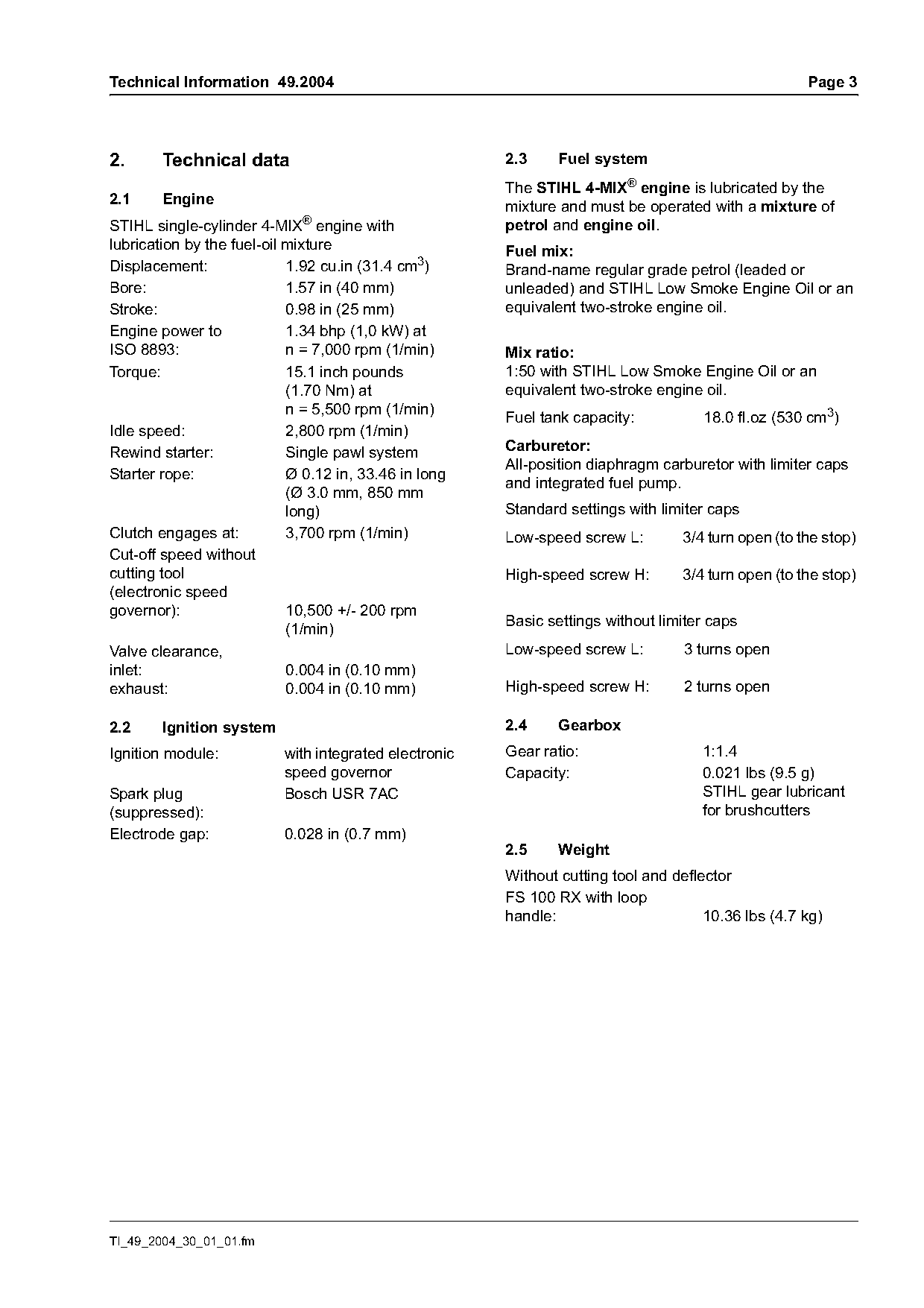
Text of page 3 — search, copy, screen readers
Technical Information 49.2004                                                                        Page 3

2.      Technical data                                  2.3     Fuel system
                                                        The STIHL 4-MIX® engine is lubricated by the
2.1     Engine                                          mixture and must be operated with a mixture of
STIHL single-cylinder 4-MIX® engine with                petrol and engine oil.
lubrication by the fuel-oil mixture                     Fuel mix:
Displacement:               1.92 cu.in (31.4 cm3)       Brand-name regular grade petrol (leaded or
Bore:                       1.57 in (40 mm)             unleaded) and STIHL Low Smoke Engine Oil or an
Stroke:                     0.98 in (25 mm)             equivalent two-stroke engine oil.
Engine power to             1.34 bhp (1,0 kW) at
ISO 8893:                   n = 7,000 rpm (1/min)       Mix ratio:
Torque:                     15.1 inch pounds            1:50 with STIHL Low Smoke Engine Oil or an
                            (1.70 Nm) at                equivalent two-stroke engine oil.
                            n = 5,500 rpm (1/min)
                                                        Fuel tank capacity:           18.0 fl.oz (530 cm3)
Idle speed:                 2,800 rpm (1/min)
Rewind starter:             Single pawl system          Carburetor:
                                                        All-position diaphragm carburetor with limiter caps
Starter rope:               Ø 0.12 in, 33.46 in long
                                                        and integrated fuel pump.
                            (Ø 3.0 mm, 850 mm
                            long)                       Standard settings with limiter caps
Clutch engages at:          3,700 rpm (1/min)           Low-speed screw L:        3/4 turn open (to the stop)
Cut-off speed without
cutting tool                                            High-speed screw H:       3/4 turn open (to the stop)
(electronic speed
governor):                  10,500 +/- 200 rpm
                                                        Basic settings without limiter caps
                            (1/min)
Valve clearance,                                        Low-speed screw L:        3 turns open
inlet:                      0.004 in (0.10 mm)
exhaust:                    0.004 in (0.10 mm)          High-speed screw H:       2 turns open

2.2     Ignition system                                 2.4     Gearbox
Ignition module:           with integrated electronic   Gear ratio:                  1:1.4
                           speed governor               Capacity:                    0.021 lbs (9.5 g)
Spark plug                 Bosch USR 7AC                                             STIHL gear lubricant
(suppressed):                                                                        for brushcutters
Electrode gap:             0.028 in (0.7 mm)
                                                        2.5     Weight
                                                        Without cutting tool and deflector
                                                        FS 100 RX with loop
                                                        handle:                       10.36 lbs (4.7 kg)

TI_49_2004_30_01_01.fm
Page 4 of 8
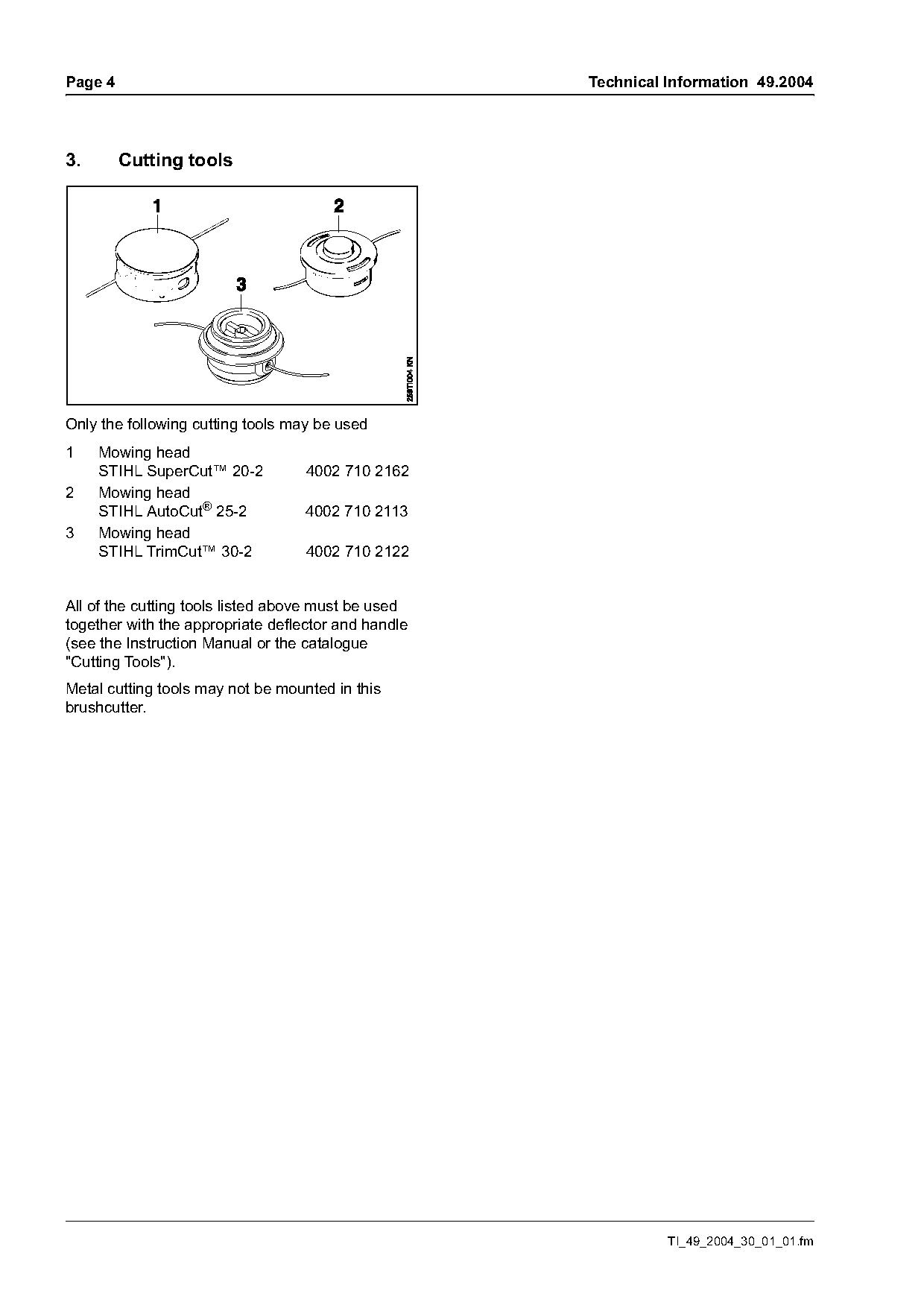
Text of page 4 — search, copy, screen readers
Page 4                                               Technical Information 49.2004

3.       Cutting tools

Only the following cutting tools may be used
1    Mowing head
     STIHL SuperCut™ 20-2          4002 710 2162
2    Mowing head
     STIHL AutoCut® 25-2           4002 710 2113
3    Mowing head
     STIHL TrimCut™ 30-2           4002 710 2122

All of the cutting tools listed above must be used
together with the appropriate deflector and handle
(see the Instruction Manual or the catalogue
"Cutting Tools").
Metal cutting tools may not be mounted in this
brushcutter.

                                                               TI_49_2004_30_01_01.fm
Page 5 of 8
Text of page 5 — search, copy, screen readers
Technical Information 49.2004                                                                       Page 5

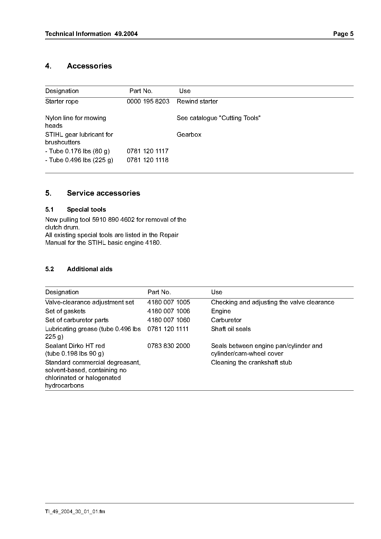
4.     Accessories

Designation                   Part No.          Use
Starter rope                 0000 195 8203      Rewind starter

Nylon line for mowing                           See catalogue "Cutting Tools"
heads
STIHL gear lubricant for                        Gearbox
brushcutters
- Tube 0.176 lbs (80 g)      0781 120 1117
- Tube 0.496 lbs (225 g)     0781 120 1118

5.     Service accessories

5.1    Special tools
New pulling tool 5910 890 4602 for removal of the
clutch drum.
All existing special tools are listed in the Repair
Manual for the STIHL basic engine 4180.

5.2    Additional aids

Designation                          Part No.              Use
Valve-clearance adjustment set       4180 007 1005         Checking and adjusting the valve clearance
Set of gaskets                       4180 007 1006         Engine
Set of carburetor parts              4180 007 1060         Carburetor
Lubricating grease (tube 0.496 lbs   0781 120 1111         Shaft oil seals
225 g)
Sealant Dirko HT red                 0783 830 2000         Seals between engine pan/cylinder and
(tube 0.198 lbs 90 g)                                      cylinder/cam-wheel cover
Standard commercial degreasant,                            Cleaning the crankshaft stub
solvent-based, containing no
chlorinated or halogenated
hydrocarbons

TI_49_2004_30_01_01.fm
Page 6 of 8
Text of page 6 — search, copy, screen readers
Page 6                                                                     Technical Information 49.2004

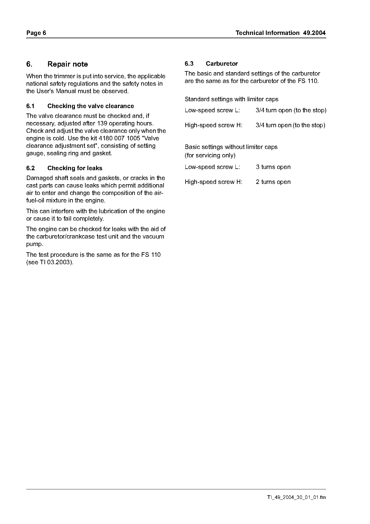
6.       Repair note                                    6.3    Carburetor

When the trimmer is put into service, the applicable    The basic and standard settings of the carburetor
national safety regulations and the safety notes in     are the same as for the carburetor of the FS 110.
the User's Manual must be observed.
                                                        Standard settings with limiter caps
6.1      Checking the valve clearance
                                                        Low-speed screw L:        3/4 turn open (to the stop)
The valve clearance must be checked and, if
necessary, adjusted after 139 operating hours.          High-speed screw H:       3/4 turn open (to the stop)
Check and adjust the valve clearance only when the
engine is cold. Use the kit 4180 007 1005 "Valve
clearance adjustment set", consisting of setting        Basic settings without limiter caps
gauge, sealing ring and gasket.                         (for servicing only)

6.2      Checking for leaks                             Low-speed screw L:        3 turns open
Damaged shaft seals and gaskets, or cracks in the
                                                        High-speed screw H:       2 turns open
cast parts can cause leaks which permit additional
air to enter and change the composition of the air-
fuel-oil mixture in the engine.
This can interfere with the lubrication of the engine
or cause it to fail completely.
The engine can be checked for leaks with the aid of
the carburetor/crankcase test unit and the vacuum
pump.
The test procedure is the same as for the FS 110
(see TI 03.2003).

                                                                                       TI_49_2004_30_01_01.fm
Page 7 of 8
Text of page 7 — search, copy, screen readers
Technical Information 49.2004                                                                                       Page 7

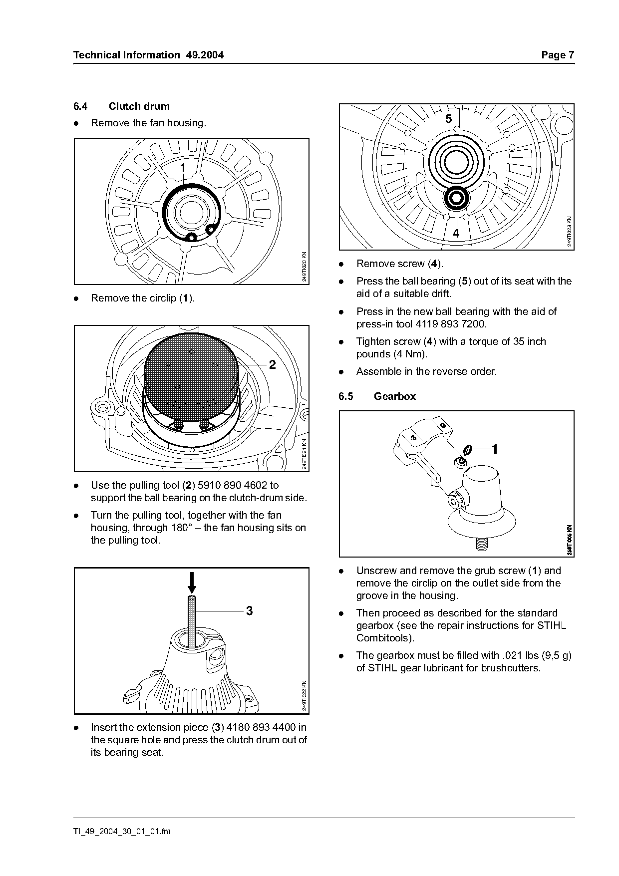
6.4       Clutch drum
.     Remove the fan housing.                                                                 5


                                                                                                                          249TI023 KN
                                                                                                  4

                                                     249TI020 KN
                                                                   .     Remove screw (4).
                                                                   .     Press the ball bearing (5) out of its seat with the
.     Remove the circlip (1).                                            aid of a suitable drift.
                                                                   .     Press in the new ball bearing with the aid of
                                                                         press-in tool 4119 893 7200.
                                                                   .     Tighten screw (4) with a torque of 35 inch
                                                                         pounds (4 Nm).
                                              2
                                                                   .     Assemble in the reverse order.

                                                                   6.5       Gearbox
                                                     249TI021 KN

.     Use the pulling tool (2) 5910 890 4602 to
      support the ball bearing on the clutch-drum side.
.     Turn the pulling tool, together with the fan
      housing, through 180° – the fan housing sits on
      the pulling tool.

                                                                   .     Unscrew and remove the grub screw (1) and
                                                                         remove the circlip on the outlet side from the
                                                                         groove in the housing.
                                         3                         .     Then proceed as described for the standard
                                                                         gearbox (see the repair instructions for STIHL
                                                                         Combitools).
                                                                   .     The gearbox must be filled with .021 lbs (9,5 g)
                                                                         of STIHL gear lubricant for brushcutters.
                                                     249TI022 KN

.     Insert the extension piece (3) 4180 893 4400 in
      the square hole and press the clutch drum out of
      its bearing seat.

TI_49_2004_30_01_01.fm
Page 8 of 8
Text of page 8 — search, copy, screen readers
Page 8                                                                       Technical Information 49.2004

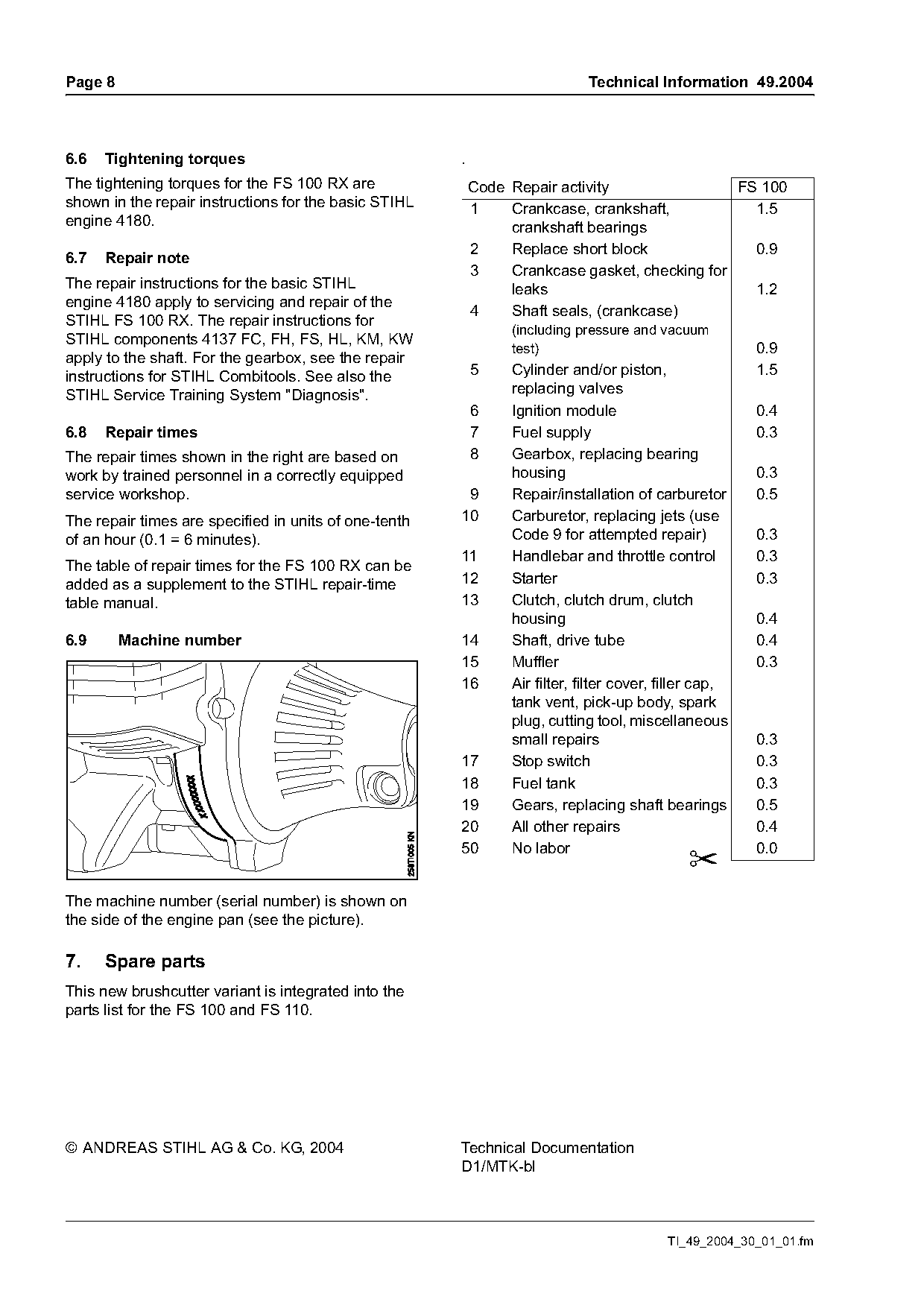
6.6   Tightening torques                               .
The tightening torques for the FS 100 RX are               Code Repair activity                FS 100
shown in the repair instructions for the basic STIHL       1    Crankcase, crankshaft,           1.5
engine 4180.                                                    crankshaft bearings
                                                           2    Replace short block              0.9
6.7   Repair note
                                                           3    Crankcase gasket, checking for
The repair instructions for the basic STIHL                     leaks                            1.2
engine 4180 apply to servicing and repair of the
                                                           4    Shaft seals, (crankcase)
STIHL FS 100 RX. The repair instructions for
                                                                (including pressure and vacuum
STIHL components 4137 FC, FH, FS, HL, KM, KW
                                                                test)                                   0.9
apply to the shaft. For the gearbox, see the repair
instructions for STIHL Combitools. See also the            5    Cylinder and/or piston,                 1.5
STIHL Service Training System "Diagnosis".                      replacing valves
                                                           6    Ignition module                         0.4
6.8   Repair times                                         7    Fuel supply                             0.3
The repair times shown in the right are based on           8    Gearbox, replacing bearing
work by trained personnel in a correctly equipped               housing                                 0.3
service workshop.                                       9       Repair/installation of carburetor       0.5
The repair times are specified in units of one-tenth   10       Carburetor, replacing jets (use
of an hour (0.1 = 6 minutes).                                   Code 9 for attempted repair)            0.3
                                                       11       Handlebar and throttle control          0.3
The table of repair times for the FS 100 RX can be
added as a supplement to the STIHL repair-time         12       Starter                                 0.3
table manual.                                          13       Clutch, clutch drum, clutch
                                                                housing                                 0.4
6.9      Machine number                                14       Shaft, drive tube                       0.4
                                                       15       Muffler                                 0.3
                                                       16       Air filter, filter cover, filler cap,
                                                                tank vent, pick-up body, spark
                                                                plug, cutting tool, miscellaneous
                                                                small repairs                           0.3
                                                       17       Stop switch                             0.3
                                                       18       Fuel tank                               0.3
                                                       19       Gears, replacing shaft bearings         0.5
                                                       20       All other repairs                       0.4
                                                       50       No labor                                0.0
The machine number (serial number) is shown on
the side of the engine pan (see the picture).

7.    Spare parts
This new brushcutter variant is integrated into the
parts list for the FS 100 and FS 110.

© ANDREAS STIHL AG & Co. KG, 2004                      Technical Documentation
                                                       D1/MTK-bl

                                                                                          TI_49_2004_30_01_01.fm
Most of these PDFs embed fonts with a shifted character map, so the text above was recovered rather than copied — read it as a faithful but imperfect transcription, and treat the page image above each block as the authority where the two disagree — the figures exist only there, because they are vector drawings that text extraction cannot keep.