Technical Information · issue 52 of 2004
Technical description; Technical data; Accessories; Service accessories; Repairs; Spare parts
IssueTI 52/2004
Full text
Page 1 of 11
Text of page 1 — search, copy, screen readers
STIH)

Technical Information                              52.2004

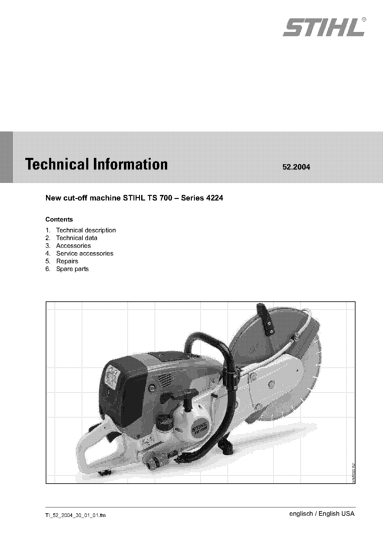
  New cut-off machine STIHL TS 700 – Series 4224

  Contents
  1.   Technical description
  2.   Technical data
  3.   Accessories
  4.   Service accessories
  5.   Repairs
  6.   Spare parts

  TI_52_2004_30_01_01.fm                            englisch / English USA
Page 2 of 11
Text of page 2 — search, copy, screen readers
Page 2                                                                     Technical Information 52.2004

The STIHL TS 700 is a handy, powerful and                the machine sets new standards for filter operating
universal cut-off machine with mountings for 14 inch     lifetimes in the sector of cut-off machines.
(350 mm) wheels. With an engine power of 5.0 kW
                                                         A further innovation is the ergonomically designed
and a maximum torque of 5.8 Nm, it is ideal for
                                                         loop handle which permits the user to hold the
demanding tasks such as operation on the STIHL
                                                         machine in various positions.
cut-off machine cart. However, its weight of only
25.6 lbs. (11.6 kg) means that it is also suitable for   The effective antivibration system, consisting of
free-hand use.                                           springs and rubber buffer elements, reduces the
                                                         vibration to which the user is subjected.
With its future-oriented technical design, the most
important feature of the TS 700 is the new engine        The controls, arranged in easy reach and marked
with stratified scavenging, which is thus ready to       with functional symbols, permit the easy operation
meet future requirements with respect to exhaust-        of all machine functions.
gas emissions. A further advantage is the long-life
air-filter system with cyclone separation, with which

1.       Technical description

1.1      Principle of operation of stratified
         scavenging
During induction, a layer of fuel-free air is
superimposed on the fresh fuel-air mixture. This
buffer between the fresh mixture in the crankcase
and the spent charge in the combustion chamber
greatly reduces the amount of fuel lost during the
exhaust event.
The following figures with the various phases of the
principle of operation are only simplified drawings of
an engine with reed valves at the top. The functions
and sequences of the engine in the STIHL TS 700
are identical to these, but the reed valves in this
engine are at the bottom of the cylinder, which
means the fresh-air path is also at the bottom, and
not at the top as shown in the drawings.

                                                                                       TI_52_2004_30_01_01.fm
Page 3 of 11
Text of page 3 — search, copy, screen readers
Technical Information 52.2004                                                                             Page 3

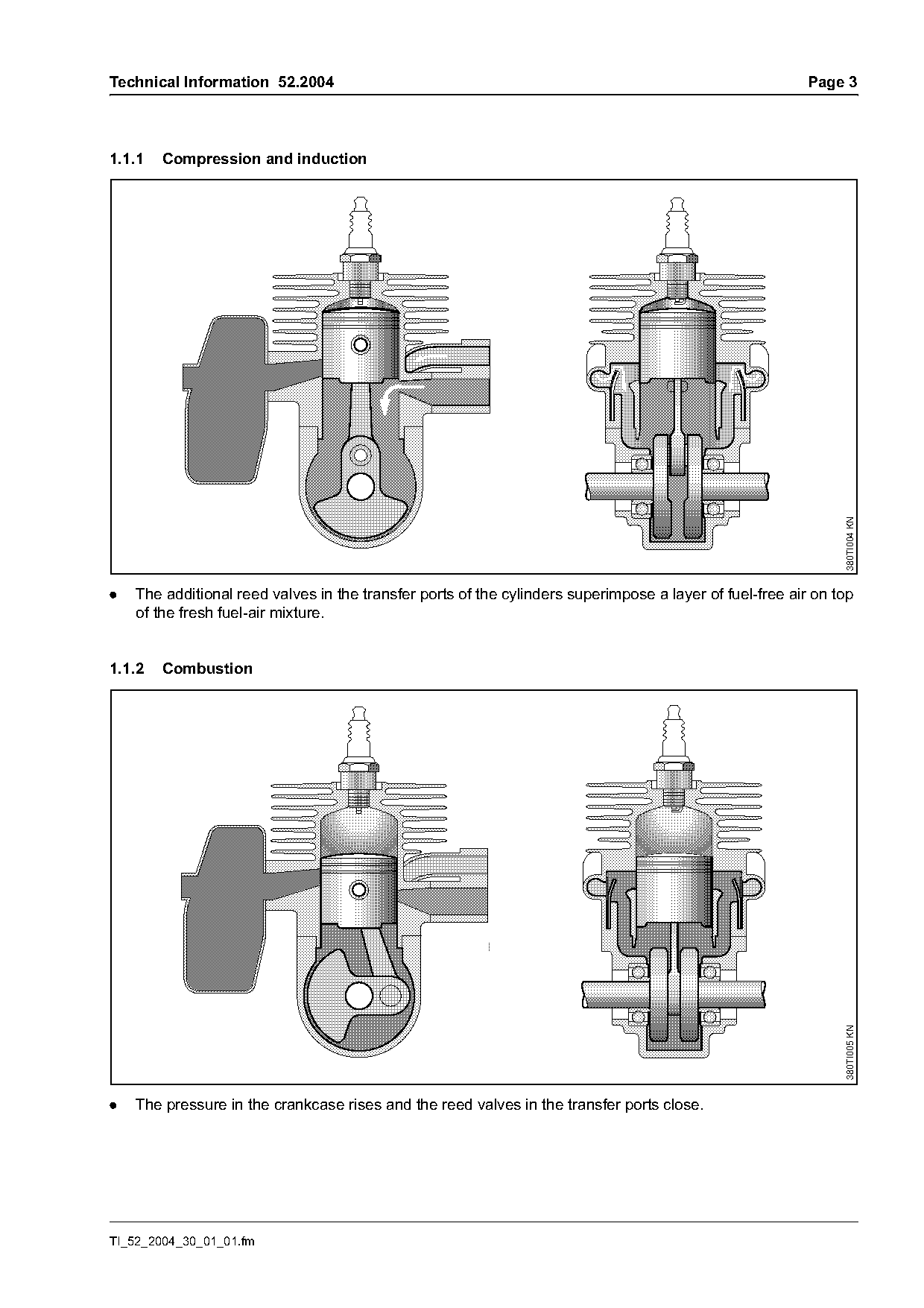
1.1.1   Compression and induction

                                                                                                                380TI004 KN
.   The additional reed valves in the transfer ports of the cylinders superimpose a layer of fuel-free air on top
    of the fresh fuel-air mixture.

1.1.2   Combustion

                                                                                                               380TI005 KN

.   The pressure in the crankcase rises and the reed valves in the transfer ports close.

TI_52_2004_30_01_01.fm
Page 4 of 11
Text of page 4 — search, copy, screen readers
Page 4                                                                   Technical Information 52.2004

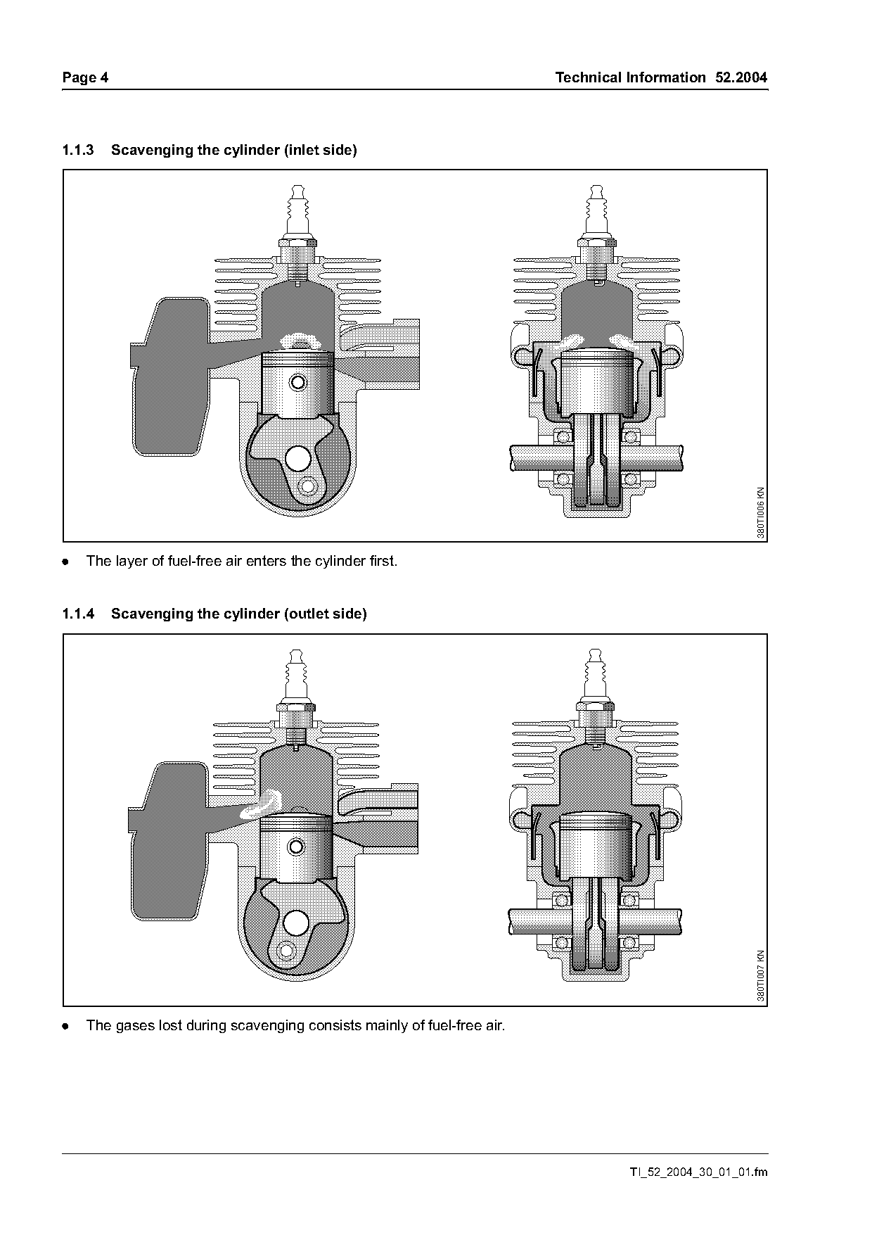
1.1.3    Scavenging the cylinder (inlet side)

                                                                                                       380TI006 KN
.   The layer of fuel-free air enters the cylinder first.

1.1.4    Scavenging the cylinder (outlet side)

                                                                                                       380TI007 KN

.   The gases lost during scavenging consists mainly of fuel-free air.

                                                                                   TI_52_2004_30_01_01.fm
Page 5 of 11
Text of page 5 — search, copy, screen readers
Technical Information 52.2004                                                                                   Page 5

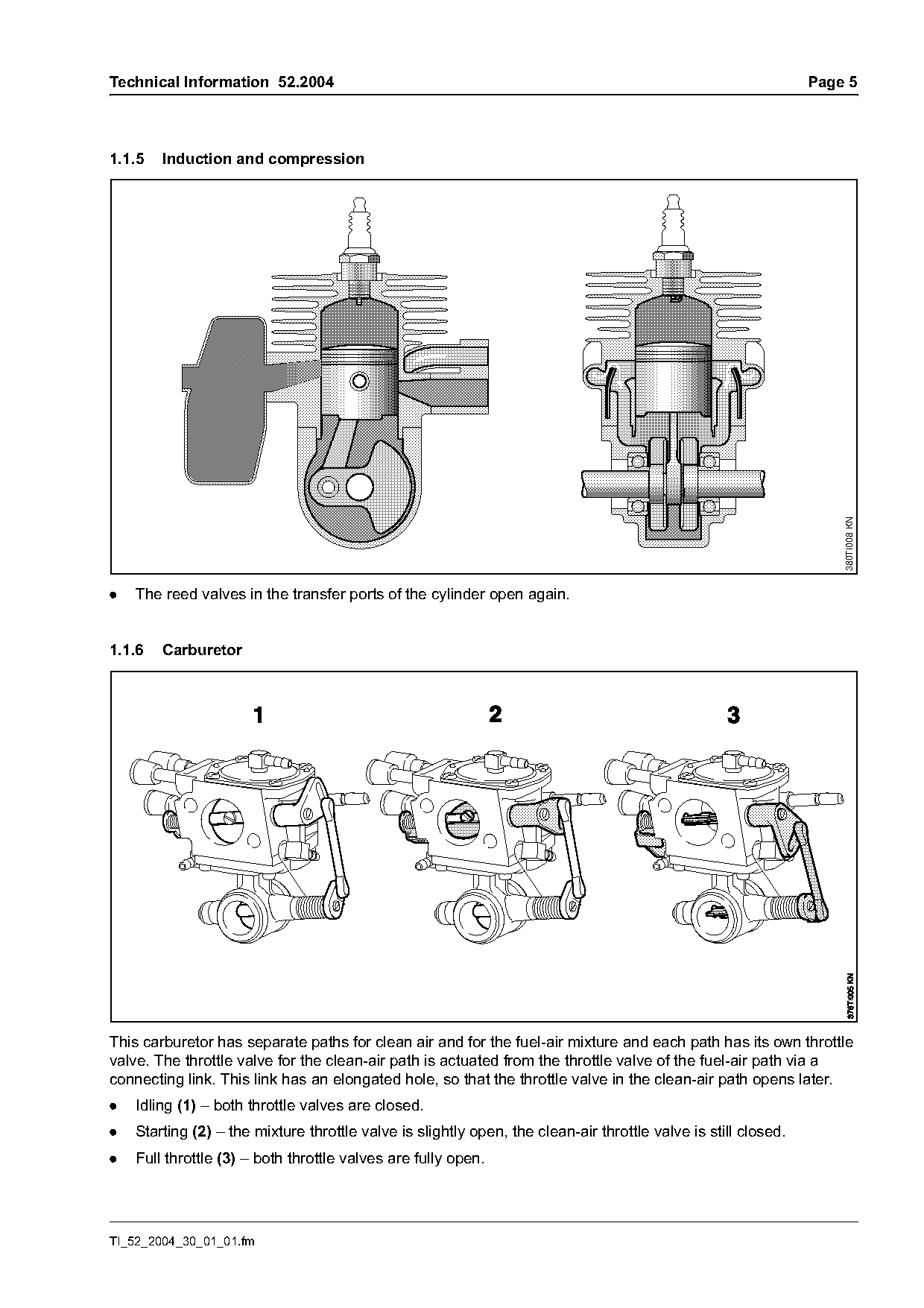
1.1.5   Induction and compression

                                                                                                                    380TI008 KN
.   The reed valves in the transfer ports of the cylinder open again.

1.1.6   Carburetor

This carburetor has separate paths for clean air and for the fuel-air mixture and each path has its own throttle
valve. The throttle valve for the clean-air path is actuated from the throttle valve of the fuel-air path via a
connecting link. This link has an elongated hole, so that the throttle valve in the clean-air path opens later.
.   Idling (1) – both throttle valves are closed.
.   Starting (2) – the mixture throttle valve is slightly open, the clean-air throttle valve is still closed.
.   Full throttle (3) – both throttle valves are fully open.

TI_52_2004_30_01_01.fm
Page 6 of 11
Text of page 6 — search, copy, screen readers
Page 6                                                                               Technical Information 52.2004

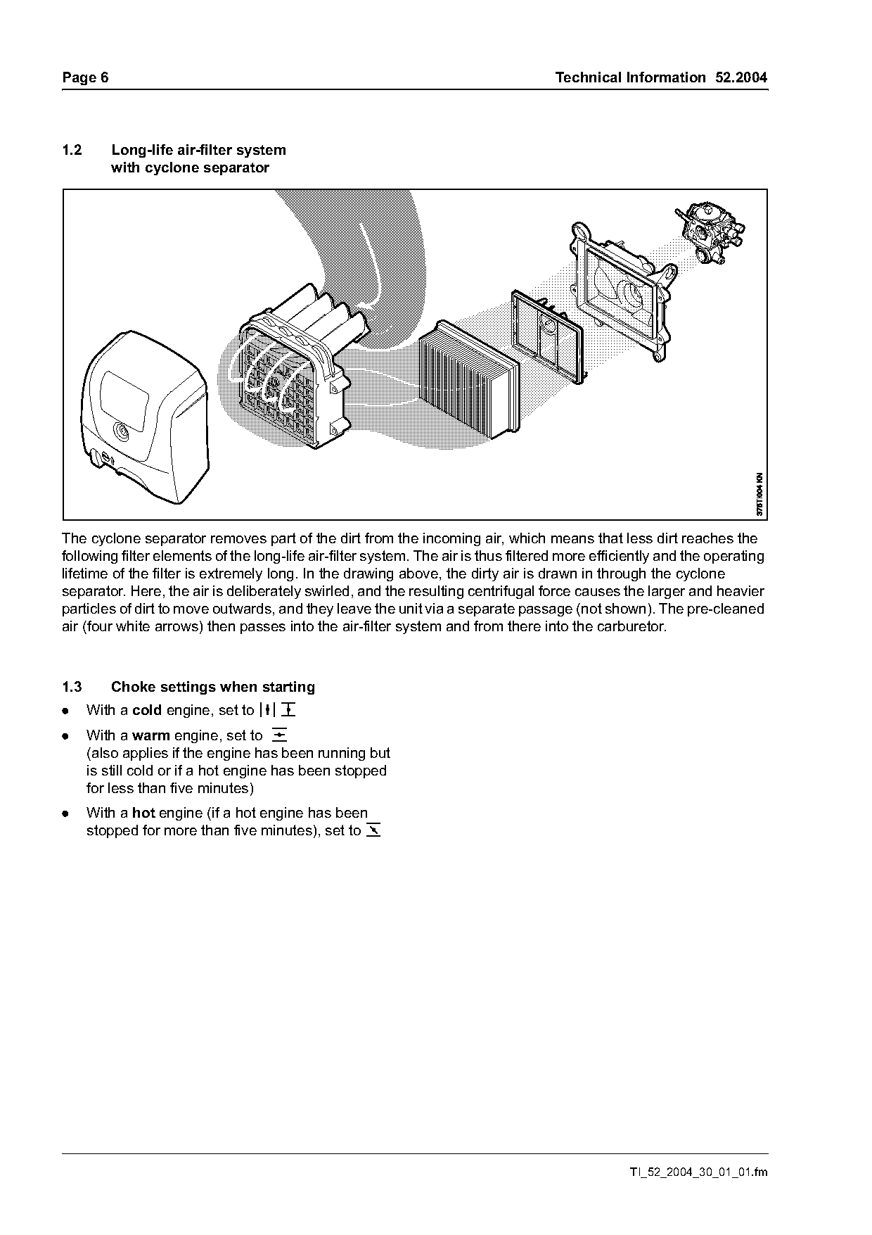
1.2       Long-life air-filter system
          with cyclone separator

The cyclone separator removes part of the dirt from the incoming air, which means that less dirt reaches the
following filter elements of the long-life air-filter system. The air is thus filtered more efficiently and the operating
lifetime of the filter is extremely long. In the drawing above, the dirty air is drawn in through the cyclone
separator. Here, the air is deliberately swirled, and the resulting centrifugal force causes the larger and heavier
particles of dirt to move outwards, and they leave the unit via a separate passage (not shown). The pre-cleaned
air (four white arrows) then passes into the air-filter system and from there into the carburetor.

1.3       Choke settings when starting
.     With a cold engine, set to j T
.     With a warm engine, set to e
      (also applies if the engine has been running but
      is still cold or if a hot engine has been stopped
      for less than five minutes)
.     With a hot engine (if a hot engine has been
      stopped for more than five minutes), set to o

                                                                                                 TI_52_2004_30_01_01.fm
Page 7 of 11
Text of page 7 — search, copy, screen readers
Technical Information 52.2004                                                                         Page 7

2.      Technical data

2.1     Engine

2.1.1   Power unit

Single-cylinder two-stroke engine
Displacement:                98.5 cm3 (6.01 cu. in.)
Bore:                        56 mm (2.205 in.)
Stroke:                      40 mm (1.575 in.)
Power to ISO 7293:           5.0 kW (6.71 bhp) at n = 9,000 rpm
Speeds:                      see section 2.1.2
Starter:                     two-pawl system
Starter rope:                4.5 mm diameter (ElastoStart)
Clutch:
– clutch engages at:         3,200 rpm

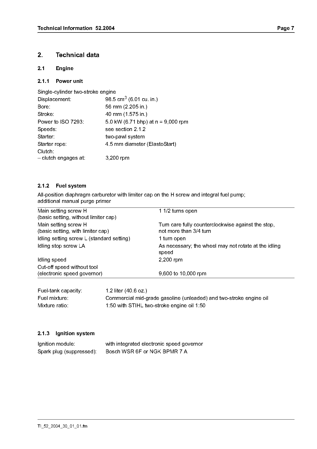
2.1.2   Fuel system
All-position diaphragm carburetor with limiter cap on the H screw and integral fuel pump;
additional manual purge primer
Main setting screw H                                1 1/2 turns open
(basic setting, without limiter cap)
Main setting screw H                                Turn care fully counterclockwise against the stop,
(basic setting, with limiter cap)                   not more than 3/4 turn
Idling setting screw L (standard setting)           1 turn open
Idling stop screw LA                                As necessary; the wheel may not rotate at the idling
                                                    speed
Idling speed                                        2,200 rpm
Cut-off speed without tool
(electronic speed governor)                         9,600 to 10,000 rpm

Fuel-tank capacity:           1.2 liter (40.6 oz.)
Fuel mixture:                 Commercial mid-grade gasoline (unleaded) and two-stroke engine oil
Mixture ratio:                1:50 with STIHL two-stroke engine oil 1:50

2.1.3   Ignition system

Ignition module:              with integrated electronic speed governor
Spark plug (suppressed):      Bosch WSR 6F or NGK BPMR 7 A

TI_52_2004_30_01_01.fm
Page 8 of 11
Text of page 8 — search, copy, screen readers
Page 8                                                                   Technical Information 52.2004

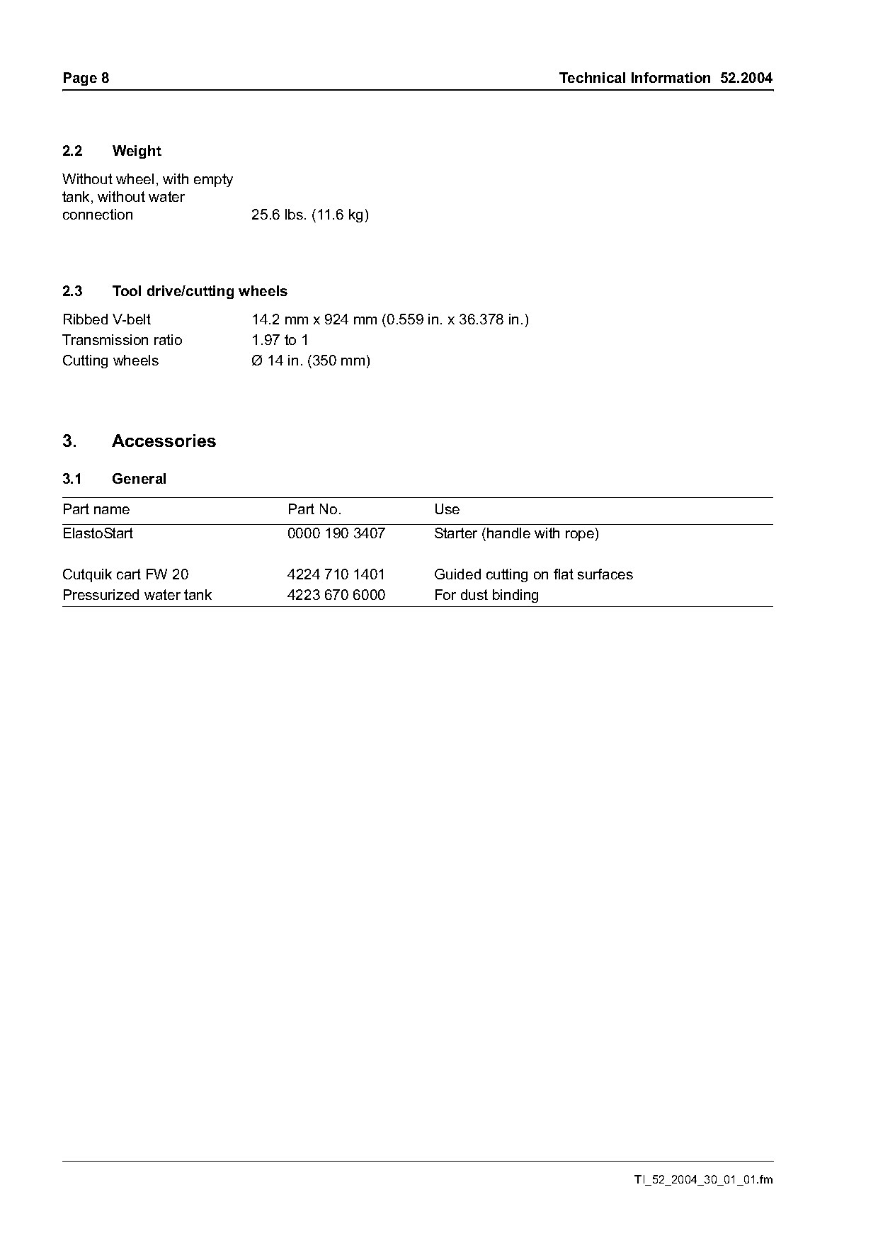
2.2      Weight
Without wheel, with empty
tank, without water
connection                  25.6 lbs. (11.6 kg)

2.3      Tool drive/cutting wheels
Ribbed V-belt               14.2 mm x 924 mm (0.559 in. x 36.378 in.)
Transmission ratio          1.97 to 1
Cutting wheels              Ø 14 in. (350 mm)

3.       Accessories

3.1      General

Part name                        Part No.             Use
ElastoStart                      0000 190 3407        Starter (handle with rope)

Cutquik cart FW 20               4224 710 1401        Guided cutting on flat surfaces
Pressurized water tank           4223 670 6000        For dust binding

                                                                                        TI_52_2004_30_01_01.fm
Page 9 of 11
Text of page 9 — search, copy, screen readers
Technical Information 52.2004                                                                         Page 9

4.       Service accessories

4.1      Special tools
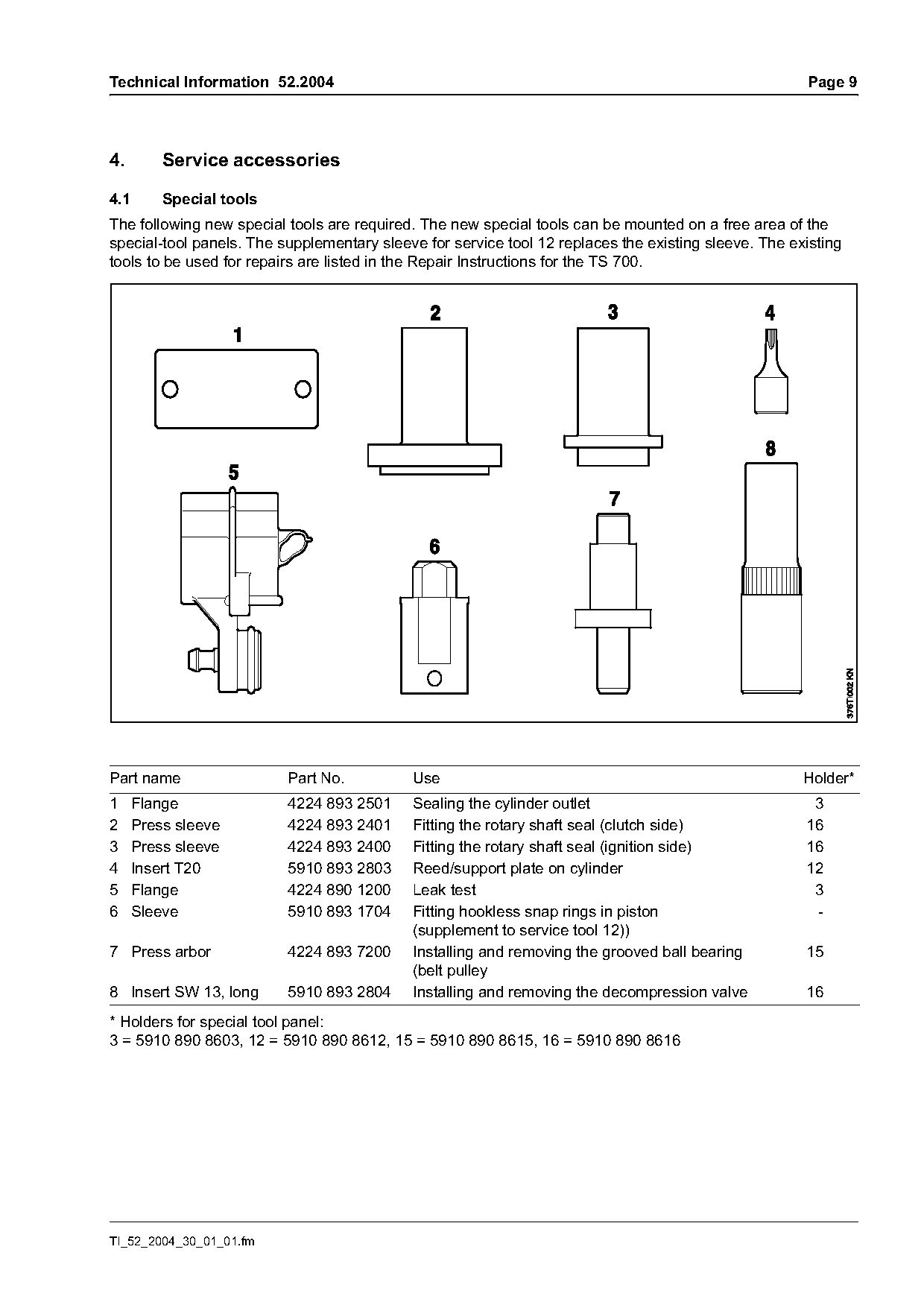
The following new special tools are required. The new special tools can be mounted on a free area of the
special-tool panels. The supplementary sleeve for service tool 12 replaces the existing sleeve. The existing
tools to be used for repairs are listed in the Repair Instructions for the TS 700.

Part name                 Part No.          Use                                                       Holder*
1    Flange               4224 893 2501     Sealing the cylinder outlet                                3
2    Press sleeve         4224 893 2401     Fitting the rotary shaft seal (clutch side)               16
3    Press sleeve         4224 893 2400     Fitting the rotary shaft seal (ignition side)             16
4    Insert T20           5910 893 2803     Reed/support plate on cylinder                            12
5    Flange               4224 890 1200     Leak test                                                  3
6    Sleeve               5910 893 1704     Fitting hookless snap rings in piston                      -
                                            (supplement to service tool 12))
7 Press arbor             4224 893 7200     Installing and removing the grooved ball bearing          15
                                            (belt pulley
8 Insert SW 13, long      5910 893 2804     Installing and removing the decompression valve           16
* Holders for special tool panel:
3 = 5910 890 8603, 12 = 5910 890 8612, 15 = 5910 890 8615, 16 = 5910 890 8616

TI_52_2004_30_01_01.fm
Page 10 of 11
Text of page 10 — search, copy, screen readers
Page 10                                                                    Technical Information 52.2004

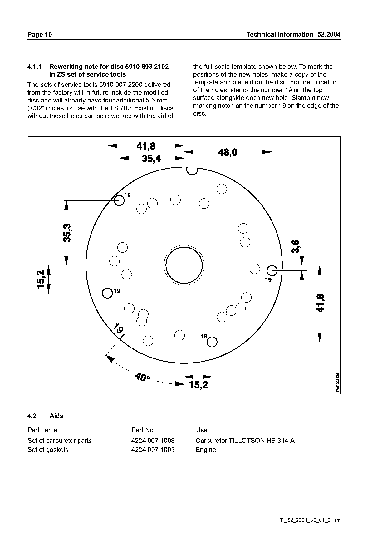
4.1.1   Reworking note for disc 5910 893 2102           the full-scale template shown below. To mark the
        in ZS set of service tools                      positions of the new holes, make a copy of the
The sets of service tools 5910 007 2200 delivered       template and place it on the disc. For identification
from the factory will in future include the modified    of the holes, stamp the number 19 on the top
disc and will already have four additional 5.5 mm       surface alongside each new hole. Stamp a new
(7/32") holes for use with the TS 700. Existing discs   marking notch an the number 19 on the edge of the
without these holes can be reworked with the aid of     disc.

4.2     Aids

Part name                            Part No.           Use
Set of carburetor parts              4224 007 1008      Carburetor TILLOTSON HS 314 A
Set of gaskets                       4224 007 1003      Engine

                                                                                       TI_52_2004_30_01_01.fm
Page 11 of 11
Text of page 11 — search, copy, screen readers
Technical Information 52.2004                                                                        Page 11

5.      Repairs
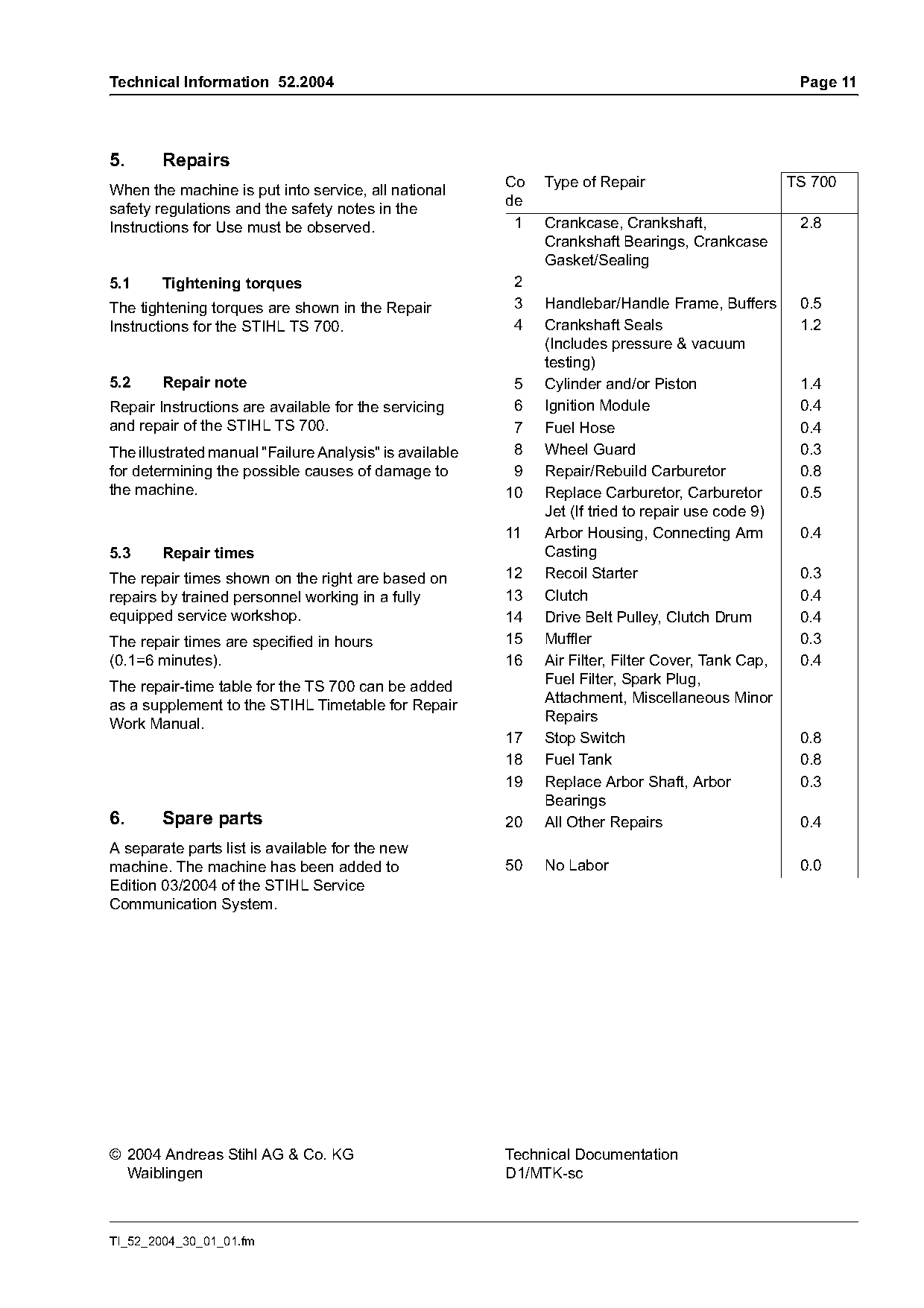
                                                         Co   Type of Repair                        TS 700
When the machine is put into service, all national
                                                         de
safety regulations and the safety notes in the
Instructions for Use must be observed.                    1   Crankcase, Crankshaft,                 2.8
                                                              Crankshaft Bearings, Crankcase
                                                              Gasket/Sealing
5.1     Tightening torques                                2
The tightening torques are shown in the Repair            3   Handlebar/Handle Frame, Buffers        0.5
Instructions for the STIHL TS 700.                        4   Crankshaft Seals                       1.2
                                                              (Includes pressure & vacuum
                                                              testing)
5.2     Repair note                                       5   Cylinder and/or Piston                 1.4
Repair Instructions are available for the servicing       6   Ignition Module                        0.4
and repair of the STIHL TS 700.                           7   Fuel Hose                              0.4
The illustrated manual "Failure Analysis" is available    8   Wheel Guard                            0.3
for determining the possible causes of damage to          9   Repair/Rebuild Carburetor              0.8
the machine.                                             10   Replace Carburetor, Carburetor         0.5
                                                              Jet (If tried to repair use code 9)
                                                         11   Arbor Housing, Connecting Arm          0.4
5.3     Repair times                                          Casting
The repair times shown on the right are based on         12   Recoil Starter                         0.3
repairs by trained personnel working in a fully          13   Clutch                                 0.4
equipped service workshop.                               14   Drive Belt Pulley, Clutch Drum         0.4
The repair times are specified in hours                  15   Muffler                                0.3
(0.1=6 minutes).                                         16   Air Filter, Filter Cover, Tank Cap,    0.4
The repair-time table for the TS 700 can be added             Fuel Filter, Spark Plug,
as a supplement to the STIHL Timetable for Repair             Attachment, Miscellaneous Minor
Work Manual.                                                  Repairs
                                                         17   Stop Switch                            0.8
                                                         18   Fuel Tank                              0.8
                                                         19   Replace Arbor Shaft, Arbor             0.3
                                                              Bearings
6.      Spare parts                                      20   All Other Repairs                      0.4
A separate parts list is available for the new
machine. The machine has been added to                   50   No Labor                               0.0
Edition 03/2004 of the STIHL Service
Communication System.

© 2004 Andreas Stihl AG & Co. KG                         Technical Documentation
  Waiblingen                                             D1/MTK-sc

TI_52_2004_30_01_01.fm
Most of these PDFs embed fonts with a shifted character map, so the text above was recovered rather than copied — read it as a faithful but imperfect transcription, and treat the page image above each block as the authority where the two disagree — the figures exist only there, because they are vector drawings that text extraction cannot keep.