Technical Information · issue 8 of 2005
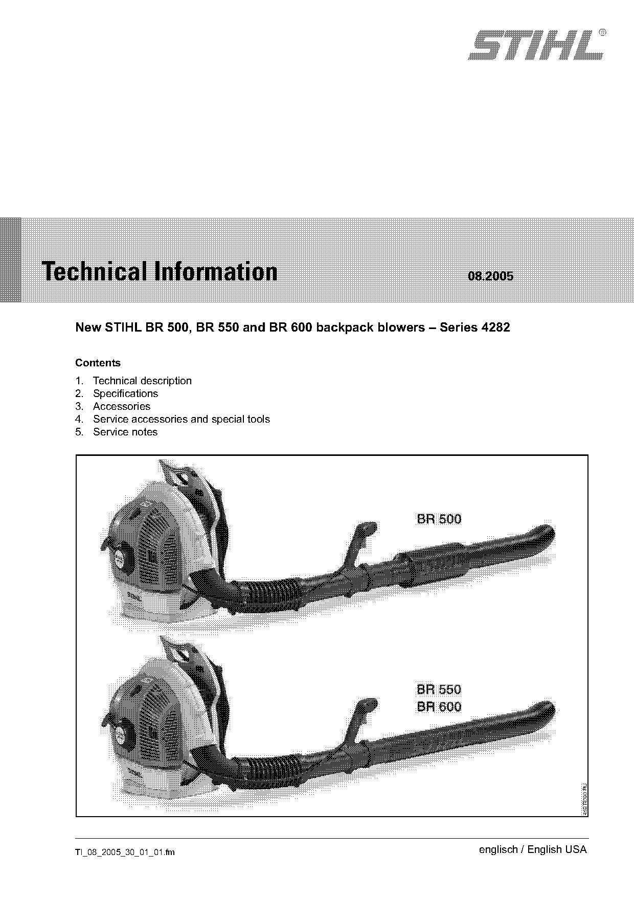
New STIHL BR 500, BR 550 and BR 600 backpack blowers
IssueTI 8/2005
Part changes (1)
| Was | Becomes | What the bulletin says |
|---|---|---|
| 4180 890 2700 | 4282 890 2700 | In the future, locking screw 4180 890 2700 will be replaced by locking screw 4282 890 2700. |
Full text
Page 1 of 22
Text of page 1 — search, copy, screen readers
STIH)

Technical Information                                        08.2005

  New STIHL BR 500, BR 550 and BR 600 backpack blowers – Series 4282

  Contents
  1.   Technical description
  2.   Specifications
  3.   Accessories
  4.   Service accessories and special tools
  5.   Service notes

  TI_08_2005_30_01_01.fm                                       englisch / English USA
Page 2 of 22
Text of page 2 — search, copy, screen readers
Page 2                                                                     Technical Information 08.2005

The new STIHL BR 500, BR 550 and BR 600               1.        Technical description
backpack blowers are designed for demanding,
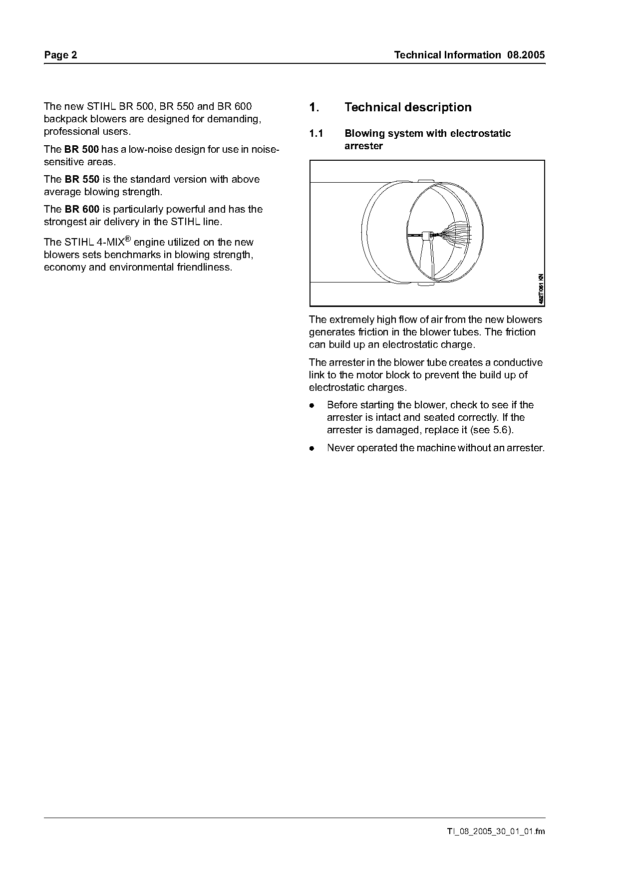
professional users.                                   1.1       Blowing system with electrostatic
The BR 500 has a low-noise design for use in noise-             arrester
sensitive areas.
The BR 550 is the standard version with above
average blowing strength.
The BR 600 is particularly powerful and has the
strongest air delivery in the STIHL line.
The STIHL 4-MIX® engine utilized on the new
blowers sets benchmarks in blowing strength,
economy and environmental friendliness.

                                                      The extremely high flow of air from the new blowers
                                                      generates friction in the blower tubes. The friction
                                                      can build up an electrostatic charge.
                                                      The arrester in the blower tube creates a conductive
                                                      link to the motor block to prevent the build up of
                                                      electrostatic charges.
                                                      .     Before starting the blower, check to see if the
                                                            arrester is intact and seated correctly. If the
                                                            arrester is damaged, replace it (see 5.6).
                                                      .     Never operated the machine without an arrester.

                                                                                       TI_08_2005_30_01_01.fm
Page 3 of 22
Text of page 3 — search, copy, screen readers
Technical Information 08.2005                                                                                 Page 3

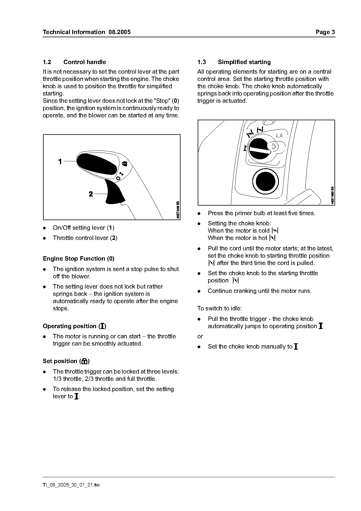
1.2       Control handle                                    1.3       Simplified starting
It is not necessary to set the control lever at the part    All operating elements for starting are on a central
throttle position when starting the engine. The choke       control area. Set the starting throttle position with
knob is used to position the throttle for simplified        the choke knob. The choke knob automatically
starting.                                                   springs back into operating position after the throttle
Since the setting lever does not lock at the "Stop" (0)     trigger is actuated.
position, the ignition system is continuously ready to
operate, and the blower can be started at any time.


                                                            .     Press the primer bulb at least five times.
                                                            .     Setting the choke knob:
.     On/Off setting lever (1)
                                                                  When the motor is cold l
.     Throttle control lever (2)                                  When the motor is hot n
                                                            .     Pull the cord until the motor starts; at the latest,
                                                                  set the choke knob to starting throttle position
Engine Stop Function (0)
                                                                  n after the third time the cord is pulled.
.     The ignition system is sent a stop pulse to shut
                                                            .     Set the choke knob to the starting throttle
      off the blower.
                                                                  position n
.     The setting lever does not lock but rather
                                                            .     Continue cranking until the motor runs.
      springs back – the ignition system is
      automatically ready to operate after the engine
      stops.                                                To switch to idle:
                                                            .     Pull the throttle trigger - the choke knob
Operating position (#)                                            automatically jumps to operating position #
.     The motor is running or can start – the throttle      or
      trigger can be smoothly actuated.                     .     Set the choke knob manually to #

Set position (C)
.     The throttle trigger can be locked at three levels:
      1/3 throttle, 2/3 throttle and full throttle.
.     To release the locked position, set the setting
      lever to #.

TI_08_2005_30_01_01.fm
Page 4 of 22
Text of page 4 — search, copy, screen readers
Page 4                                                                         Technical Information 08.2005

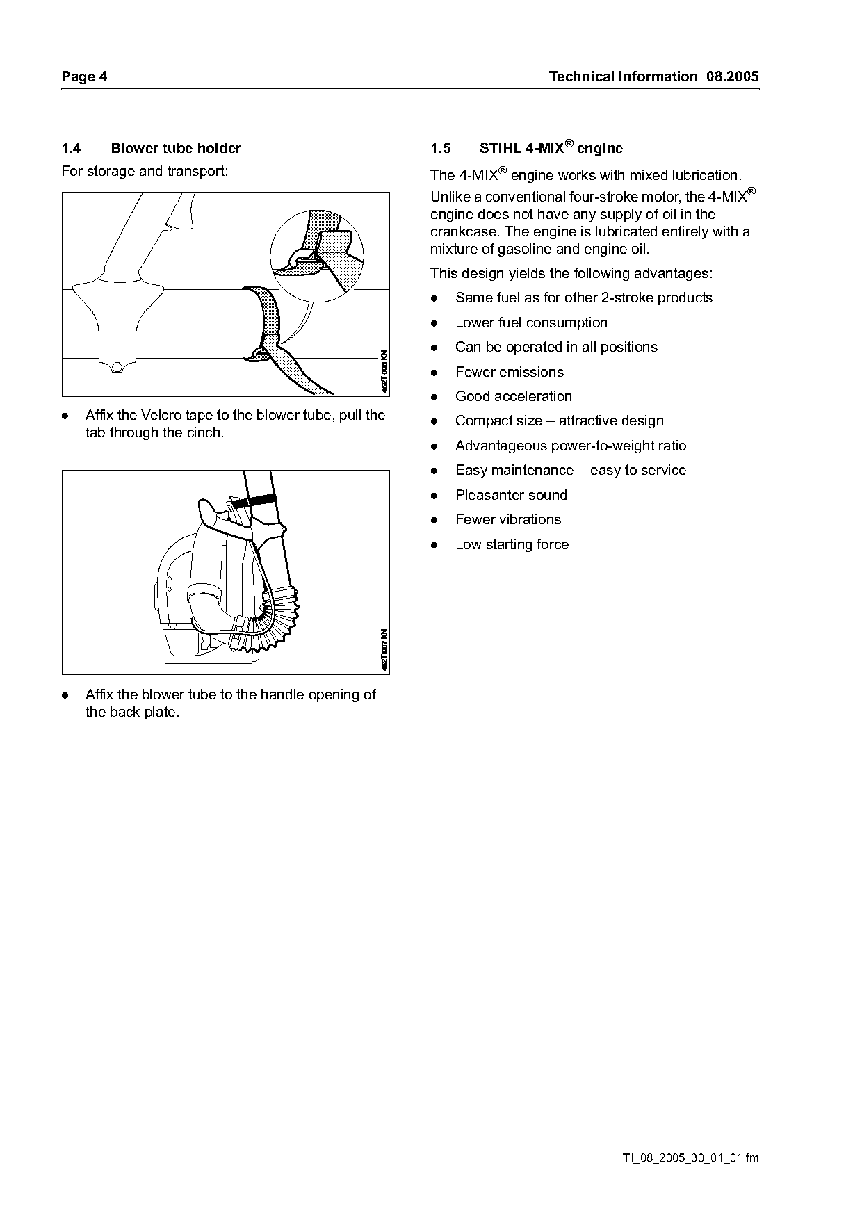
1.4       Blower tube holder                               1.5      STIHL 4-MIX® engine
For storage and transport:                                 The 4-MIX® engine works with mixed lubrication.
                                                           Unlike a conventional four-stroke motor, the 4-MIX®
                                                           engine does not have any supply of oil in the
                                                           crankcase. The engine is lubricated entirely with a
                                                           mixture of gasoline and engine oil.
                                                           This design yields the following advantages:
                                                           .     Same fuel as for other 2-stroke products
                                                           .     Lower fuel consumption
                                                           .     Can be operated in all positions
                                                           .     Fewer emissions
                                                           .     Good acceleration
.     Affix the Velcro tape to the blower tube, pull the   .     Compact size – attractive design
      tab through the cinch.
                                                           .     Advantageous power-to-weight ratio
                                                           .     Easy maintenance – easy to service
                                                           .     Pleasanter sound
                                                           .     Fewer vibrations
                                                           .     Low starting force

.     Affix the blower tube to the handle opening of
      the back plate.

                                                                                           TI_08_2005_30_01_01.fm
Page 5 of 22
Text of page 5 — search, copy, screen readers
Technical Information 08.2005                                                                        Page 5

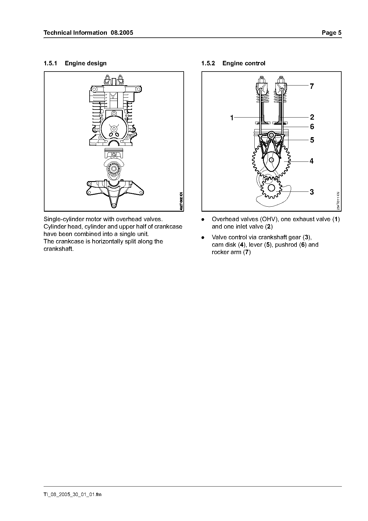
1.5.1   Engine design                                 1.5.2   Engine control


                                                                1                             2
                                                                                              6
                                                                                              5


                                                                                                         254TI011 KN
Single-cylinder motor with overhead valves.           .   Overhead valves (OHV), one exhaust valve (1)
Cylinder head, cylinder and upper half of crankcase       and one inlet valve (2)
have been combined into a single unit.                .   Valve control via crankshaft gear (3),
The crankcase is horizontally split along the             cam disk (4), lever (5), pushrod (6) and
crankshaft.
                                                          rocker arm (7)

TI_08_2005_30_01_01.fm
Page 6 of 22
Text of page 6 — search, copy, screen readers
Page 6                                                                       Technical Information 08.2005

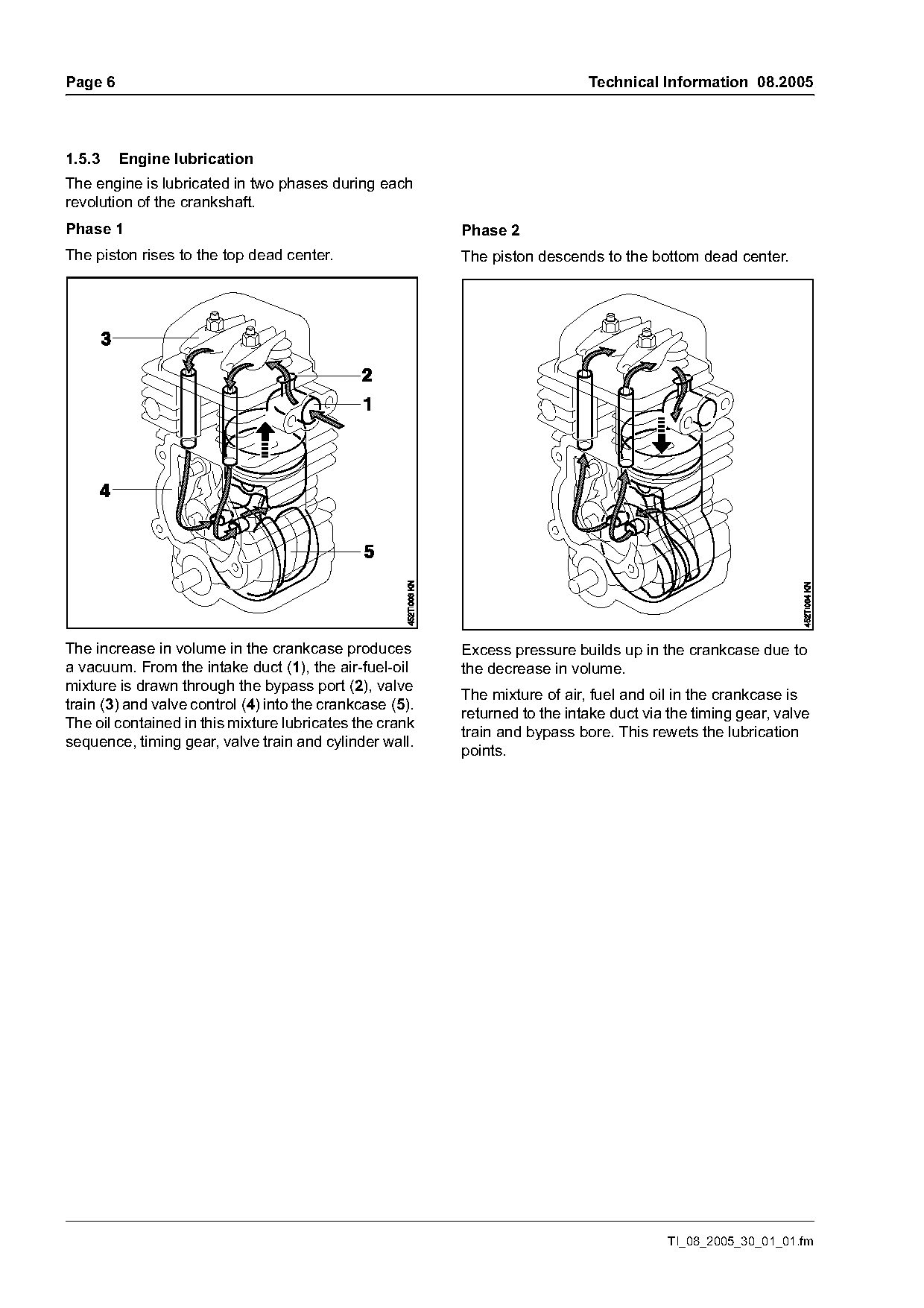
1.5.3    Engine lubrication
The engine is lubricated in two phases during each
revolution of the crankshaft.
Phase 1                                                   Phase 2
The piston rises to the top dead center.                  The piston descends to the bottom dead center.

The increase in volume in the crankcase produces          Excess pressure builds up in the crankcase due to
a vacuum. From the intake duct (1), the air-fuel-oil      the decrease in volume.
mixture is drawn through the bypass port (2), valve
                                                          The mixture of air, fuel and oil in the crankcase is
train (3) and valve control (4) into the crankcase (5).
                                                          returned to the intake duct via the timing gear, valve
The oil contained in this mixture lubricates the crank
                                                          train and bypass bore. This rewets the lubrication
sequence, timing gear, valve train and cylinder wall.
                                                          points.

                                                                                          TI_08_2005_30_01_01.fm
Page 7 of 22
Text of page 7 — search, copy, screen readers
Technical Information 08.2005                                                                              Page 7

1.6      Decompression system                            1.7       Carburetor
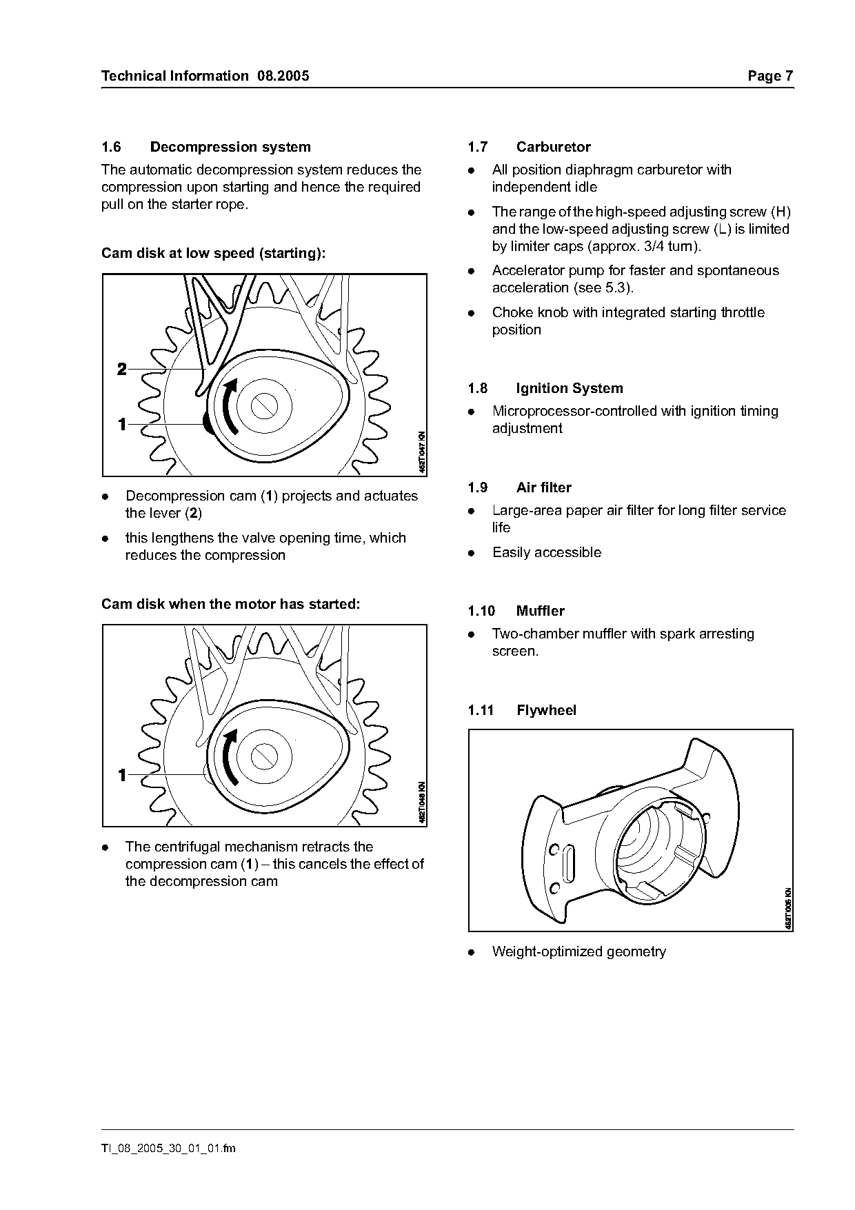
The automatic decompression system reduces the           .     All position diaphragm carburetor with
compression upon starting and hence the required               independent idle
pull on the starter rope.                                .     The range of the high-speed adjusting screw (H)
                                                               and the low-speed adjusting screw (L) is limited
                                                               by limiter caps (approx. 3/4 turn).
Cam disk at low speed (starting):
                                                         .     Accelerator pump for faster and spontaneous
                                                               acceleration (see 5.3).
                                                         .     Choke knob with integrated starting throttle
                                                               position

                                                         1.8       Ignition System
                                                         .     Microprocessor-controlled with ignition timing
                                                               adjustment

                                                         1.9       Air filter
.     Decompression cam (1) projects and actuates
      the lever (2)                                      .     Large-area paper air filter for long filter service
                                                               life
.     this lengthens the valve opening time, which
      reduces the compression                            .     Easily accessible

Cam disk when the motor has started:                     1.10      Muffler
                                                         .     Two-chamber muffler with spark arresting
                                                               screen.

                                                         1.11      Flywheel

.     The centrifugal mechanism retracts the
      compression cam (1) – this cancels the effect of
      the decompression cam

                                                         .     Weight-optimized geometry

TI_08_2005_30_01_01.fm
Page 8 of 22
Text of page 8 — search, copy, screen readers
Page 8                                                                          Technical Information 08.2005

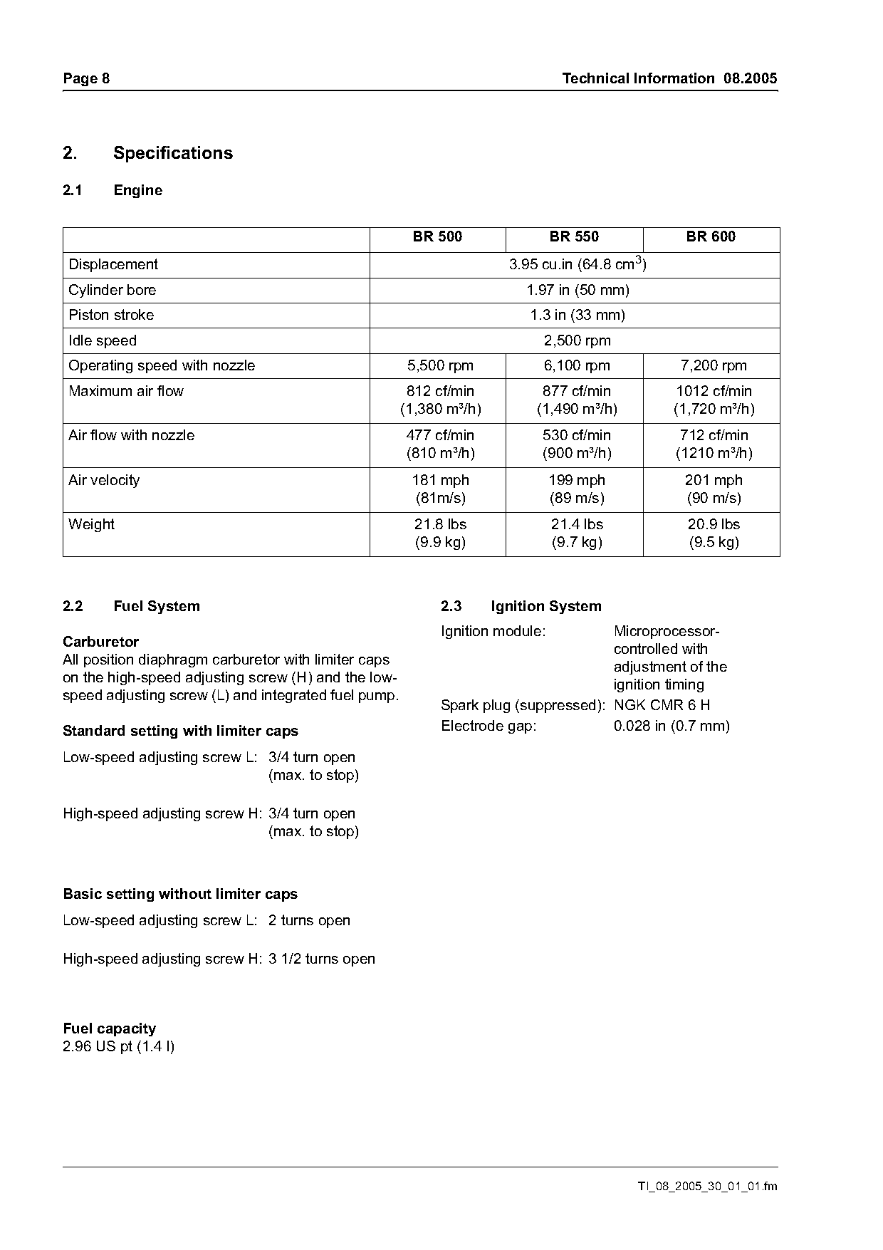
2.       Specifications

2.1      Engine

                                                       BR 500                  BR 550             BR 600
Displacement                                                           3.95 cu.in (64.8 cm3)
Cylinder bore                                                            1.97 in (50 mm)
Piston stroke                                                             1.3 in (33 mm)
Idle speed                                                                  2,500 rpm
Operating speed with nozzle                            5,500 rpm            6,100 rpm            7,200 rpm
Maximum air flow                                       812 cf/min           877 cf/min          1012 cf/min
                                                      (1,380 m³/h)         (1,490 m³/h)         (1,720 m³/h)
Air flow with nozzle                                  477 cf/min            530 cf/min           712 cf/min
                                                      (810 m³/h)            (900 m³/h)          (1210 m³/h)
Air velocity                                           181 mph                 199 mph            201 mph
                                                       (81m/s)                 (89 m/s)           (90 m/s)
Weight                                                  21.8 lbs               21.4 lbs           20.9 lbs
                                                        (9.9 kg)               (9.7 kg)           (9.5 kg)

2.2      Fuel System                                        2.3      Ignition System
                                                            Ignition module:         Microprocessor-
Carburetor
                                                                                     controlled with
All position diaphragm carburetor with limiter caps
                                                                                     adjustment of the
on the high-speed adjusting screw (H) and the low-
                                                                                     ignition timing
speed adjusting screw (L) and integrated fuel pump.
                                                            Spark plug (suppressed): NGK CMR 6 H
Standard setting with limiter caps                          Electrode gap:           0.028 in (0.7 mm)

Low-speed adjusting screw L: 3/4 turn open
                             (max. to stop)

High-speed adjusting screw H: 3/4 turn open
                              (max. to stop)

Basic setting without limiter caps
Low-speed adjusting screw L: 2 turns open

High-speed adjusting screw H: 3 1/2 turns open

Fuel capacity
2.96 US pt (1.4 l)

                                                                                           TI_08_2005_30_01_01.fm
Page 9 of 22
Text of page 9 — search, copy, screen readers
Technical Information 08.2005                                                                         Page 9

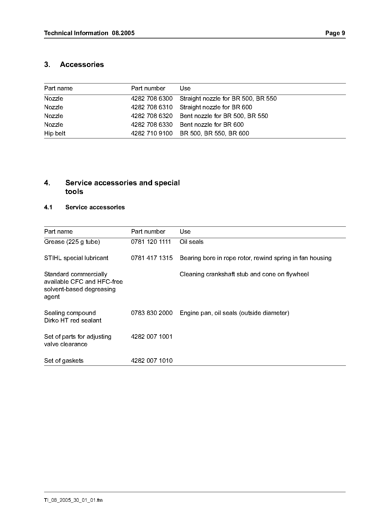
3.    Accessories

Part name                        Part number     Use
Nozzle                           4282 708 6300   Straight nozzle for BR 500, BR 550
Nozzle                           4282 708 6310   Straight nozzle for BR 600
Nozzle                           4282 708 6320   Bent nozzle for BR 500, BR 550
Nozzle                           4282 708 6330   Bent nozzle for BR 600
Hip belt                         4282 710 9100   BR 500, BR 550, BR 600

4.         Service accessories and special
           tools

4.1        Service accessories

Part name                        Part number     Use
Grease (225 g tube)              0781 120 1111   Oil seals

STIHL special lubricant          0781 417 1315   Bearing bore in rope rotor, rewind spring in fan housing

Standard commercially                            Cleaning crankshaft stub and cone on flywheel
available CFC and HFC-free
solvent-based degreasing
agent

Sealing compound                 0783 830 2000   Engine pan, oil seals (outside diameter)
Dirko HT red sealant

Set of parts for adjusting       4282 007 1001
valve clearance

Set of gaskets                   4282 007 1010

TI_08_2005_30_01_01.fm
Page 10 of 22
Text of page 10 — search, copy, screen readers
Page 10                                                                           Technical Information 08.2005

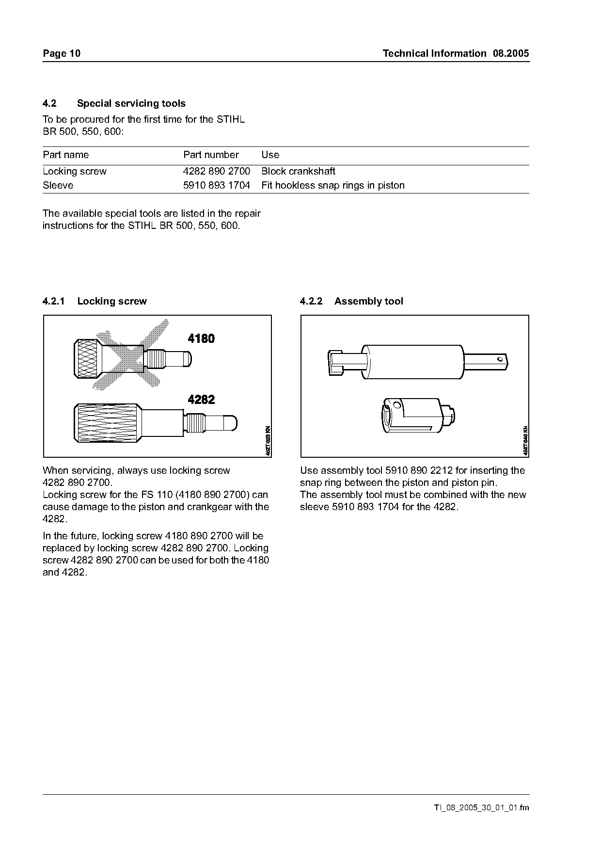
4.2     Special servicing tools
To be procured for the first time for the STIHL
BR 500, 550, 600:

Part name                        Part number           Use
Locking screw                    4282 890 2700         Block crankshaft
Sleeve                           5910 893 1704         Fit hookless snap rings in piston

The available special tools are listed in the repair
instructions for the STIHL BR 500, 550, 600.

4.2.1   Locking screw                                          4.2.2   Assembly tool

When servicing, always use locking screw                       Use assembly tool 5910 890 2212 for inserting the
4282 890 2700.                                                 snap ring between the piston and piston pin.
Locking screw for the FS 110 (4180 890 2700) can               The assembly tool must be combined with the new
cause damage to the piston and crankgear with the              sleeve 5910 893 1704 for the 4282.
4282.
In the future, locking screw 4180 890 2700 will be
replaced by locking screw 4282 890 2700. Locking
screw 4282 890 2700 can be used for both the 4180
and 4282.

                                                                                            TI_08_2005_30_01_01.fm
Page 11 of 22
Text of page 11 — search, copy, screen readers
Technical Information 08.2005                                                                                      Page 11

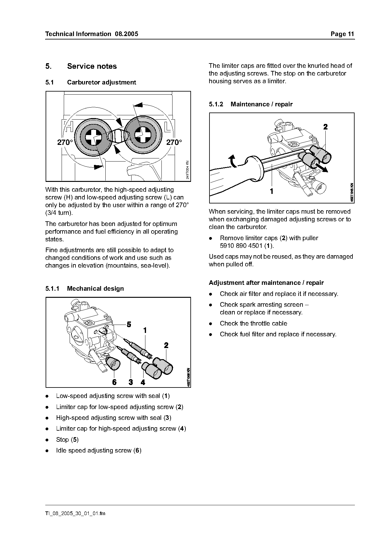
5.       Service notes                                               The limiter caps are fitted over the knurled head of
                                                                     the adjusting screws. The stop on the carburetor
5.1      Carburetor adjustment                                       housing serves as a limiter.

                                                                     5.1.2   Maintenance / repair

      270°                                   270°

                                                       249TI004 KN
With this carburetor, the high-speed adjusting
screw (H) and low-speed adjusting screw (L) can
only be adjusted by the user within a range of 270°
(3/4 turn).                                                          When servicing, the limiter caps must be removed
                                                                     when exchanging damaged adjusting screws or to
The carburetor has been adjusted for optimum
                                                                     clean the carburetor.
performance and fuel efficiency in all operating
states.                                                              .   Remove limiter caps (2) with puller
                                                                         5910 890 4501 (1).
Fine adjustments are still possible to adapt to
changed conditions of work and use such as                           Used caps may not be reused, as they are damaged
changes in elevation (mountains, sea-level).                         when pulled off.

                                                                     Adjustment after maintenance / repair
5.1.1    Mechanical design
                                                                     .   Check air filter and replace it if necessary.
                                                                     .   Check spark arresting screen –
                                                                         clean or replace if necessary.
                                                                     .   Check the throttle cable
                                                                     .   Check fuel filter and replace if necessary.

.     Low-speed adjusting screw with seal (1)
.     Limiter cap for low-speed adjusting screw (2)
.     High-speed adjusting screw with seal (3)
.     Limiter cap for high-speed adjusting screw (4)
.     Stop (5)
.     Idle speed adjusting screw (6)

TI_08_2005_30_01_01.fm
Page 12 of 22
Text of page 12 — search, copy, screen readers
Page 12                                                                     Technical Information 08.2005

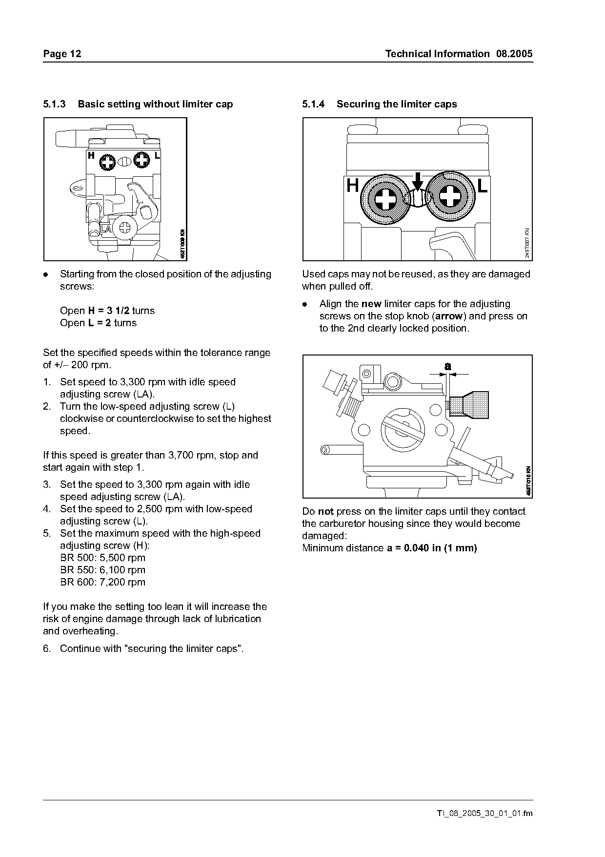
5.1.3   Basic setting without limiter cap                5.1.4   Securing the limiter caps

                                                                  H                             L

                                                                                                           249TI007 KN
.   Starting from the closed position of the adjusting   Used caps may not be reused, as they are damaged
    screws:                                              when pulled off.
                                                         .   Align the new limiter caps for the adjusting
    Open H = 3 1/2 turns                                     screws on the stop knob (arrow) and press on
    Open L = 2 turns                                         to the 2nd clearly locked position.

Set the specified speeds within the tolerance range
of +/– 200 rpm.
1. Set speed to 3,300 rpm with idle speed
   adjusting screw (LA).
2. Turn the low-speed adjusting screw (L)
   clockwise or counterclockwise to set the highest
   speed.

If this speed is greater than 3,700 rpm, stop and
start again with step 1.
3. Set the speed to 3,300 rpm again with idle
   speed adjusting screw (LA).
4. Set the speed to 2,500 rpm with low-speed             Do not press on the limiter caps until they contact
   adjusting screw (L).                                  the carburetor housing since they would become
5. Set the maximum speed with the high-speed             damaged:
   adjusting screw (H):                                  Minimum distance a = 0.040 in (1 mm)
   BR 500: 5,500 rpm
   BR 550: 6,100 rpm
   BR 600: 7,200 rpm

If you make the setting too lean it will increase the
risk of engine damage through lack of lubrication
and overheating.
6. Continue with "securing the limiter caps".

                                                                                       TI_08_2005_30_01_01.fm
Page 13 of 22
Text of page 13 — search, copy, screen readers
Technical Information 08.2005                                                                            Page 13

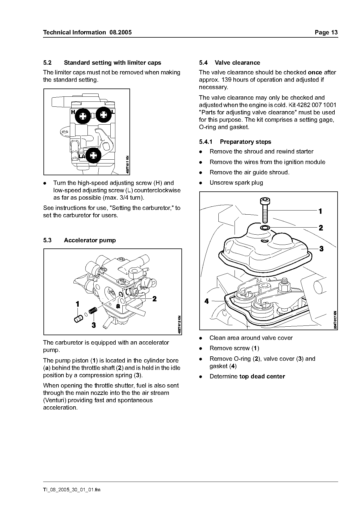
5.2      Standard setting with limiter caps                 5.4     Valve clearance
The limiter caps must not be removed when making            The valve clearance should be checked once after
the standard setting.                                       approx. 139 hours of operation and adjusted if
                                                            necessary.
                                                            The valve clearance may only be checked and
                                                            adjusted when the engine is cold. Kit 4282 007 1001
                                                            "Parts for adjusting valve clearance" must be used
                                                            for this purpose. The kit comprises a setting gage,
                                                            O-ring and gasket.

                                                            5.4.1    Preparatory steps
                                                            .     Remove the shroud and rewind starter
                                                            .     Remove the wires from the ignition module
                                                            .     Remove the air guide shroud.
.     Turn the high-speed adjusting screw (H) and           .     Unscrew spark plug
      low-speed adjusting screw (L) counterclockwise
      as far as possible (max. 3/4 turn).
See instructions for use, "Setting the carburetor," to
set the carburetor for users.

5.3      Accelerator pump

                                                            .     Clean area around valve cover
The carburetor is equipped with an accelerator
pump.                                                       .     Remove screw (1)

The pump piston (1) is located in the cylinder bore         .     Remove O-ring (2), valve cover (3) and
(a) behind the throttle shaft (2) and is held in the idle         gasket (4)
position by a compression spring (3).                       .     Determine top dead center
When opening the throttle shutter, fuel is also sent
through the main nozzle into the the air stream
(Venturi) providing fast and spontaneous
acceleration.

TI_08_2005_30_01_01.fm
Page 14 of 22
Text of page 14 — search, copy, screen readers
Page 14                                                                           Technical Information 08.2005

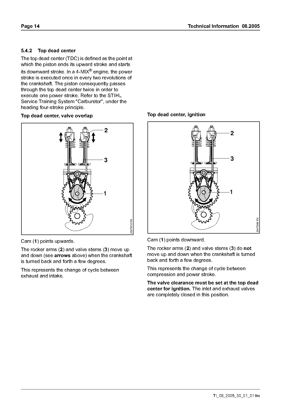
5.4.2   Top dead center
The top dead center (TDC) is defined as the point at
which the piston ends its upward stroke and starts
its downward stroke. In a 4-MIX® engine, the power
stroke is executed once in every two revolutions of
the crankshaft. The piston consequently passes
through the top dead center twice in order to
execute one power stroke. Refer to the STIHL
Service Training System "Carburetor", under the
heading four-stroke principle.
Top dead center, valve overlap                                   Top dead center, ignition

                                       2                                                              2

                                      3                                                               3

                                      1                                                              1

                                                                                                                  254TI009 KN
                                                   254TI010 KN

Cam (1) points upwards.                                          Cam (1) points downward.
The rocker arms (2) and valve stems (3) move up                  The rocker arms (2) and valve stems (3) do not
and down (see arrows above) when the crankshaft                  move up and down when the crankshaft is turned
is turned back and forth a few degrees.                          back and forth a few degrees.
This represents the change of cycle between                      This represents the change of cycle between
exhaust and intake.                                              compression and power stroke.
                                                                 The valve clearance must be set at the top dead
                                                                 center for ignition. The inlet and exhaust valves
                                                                 are completely closed in this position.

                                                                                              TI_08_2005_30_01_01.fm
Page 15 of 22
Text of page 15 — search, copy, screen readers
Technical Information 08.2005                                                                          Page 15

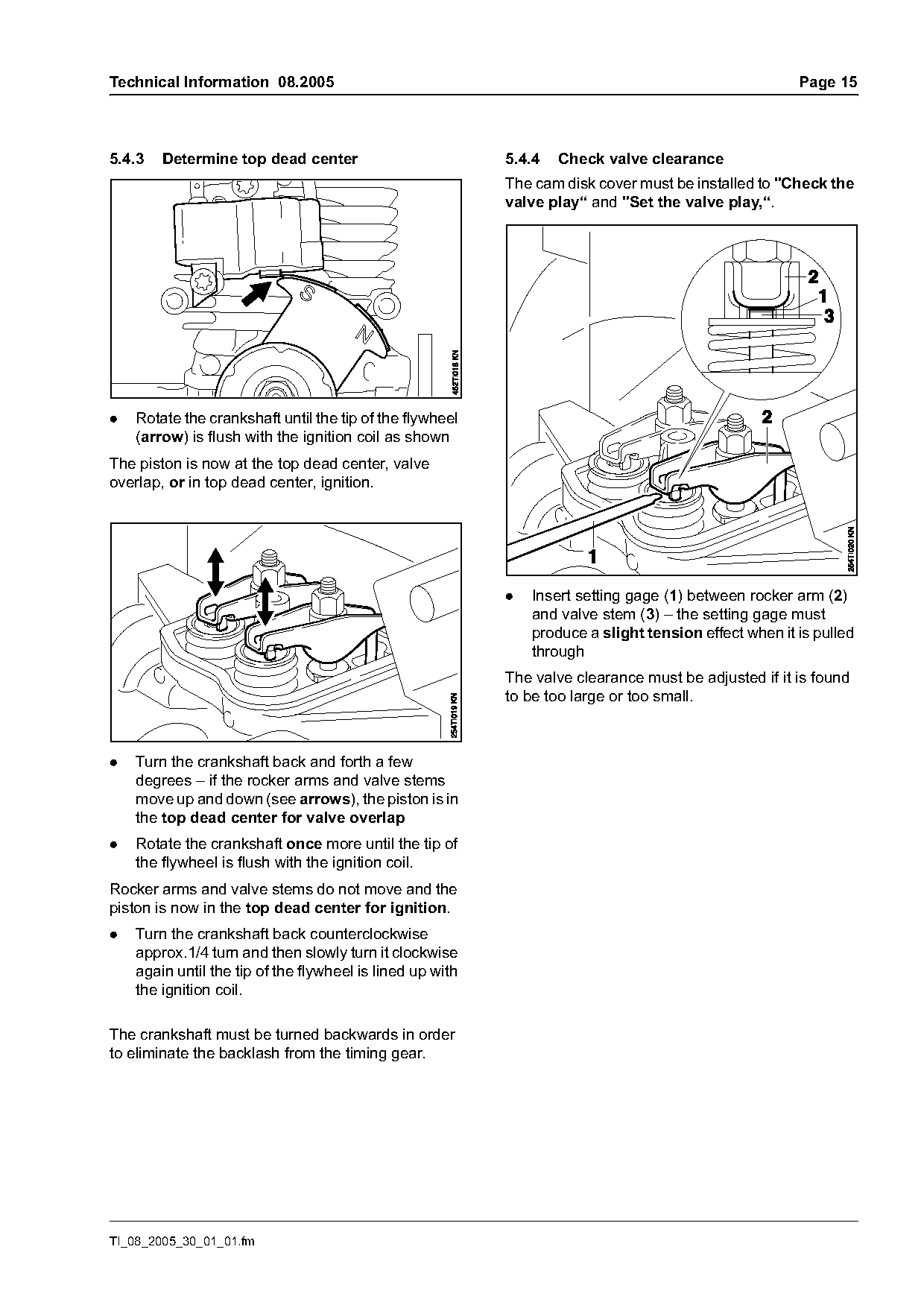
5.4.3   Determine top dead center                          5.4.4   Check valve clearance
                                                           The cam disk cover must be installed to "Check the
                                                           valve play“ and "Set the valve play,“.

.   Rotate the crankshaft until the tip of the flywheel
    (arrow) is flush with the ignition coil as shown
The piston is now at the top dead center, valve
overlap, or in top dead center, ignition.

                                                           .   Insert setting gage (1) between rocker arm (2)
                                                               and valve stem (3) – the setting gage must
                                                               produce a slight tension effect when it is pulled
                                                               through
                                                           The valve clearance must be adjusted if it is found
                                                           to be too large or too small.

.   Turn the crankshaft back and forth a few
    degrees – if the rocker arms and valve stems
    move up and down (see arrows), the piston is in
    the top dead center for valve overlap
.   Rotate the crankshaft once more until the tip of
    the flywheel is flush with the ignition coil.
Rocker arms and valve stems do not move and the
piston is now in the top dead center for ignition.
.   Turn the crankshaft back counterclockwise
    approx.1/4 turn and then slowly turn it clockwise
    again until the tip of the flywheel is lined up with
    the ignition coil.

The crankshaft must be turned backwards in order
to eliminate the backlash from the timing gear.

TI_08_2005_30_01_01.fm
Page 16 of 22
Text of page 16 — search, copy, screen readers
Page 16                                                                   Technical Information 08.2005

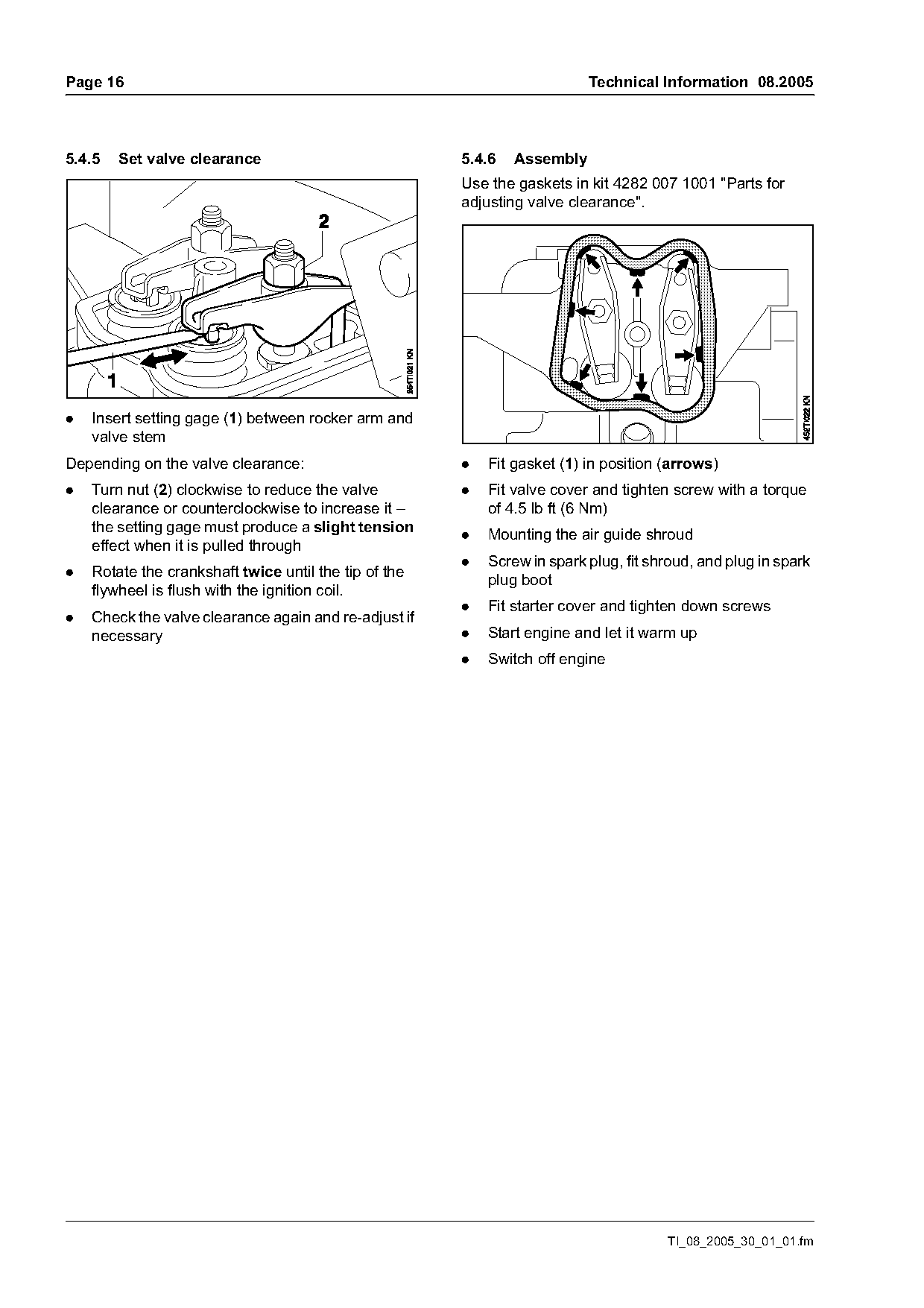
5.4.5   Set valve clearance                            5.4.6   Assembly
                                                       Use the gaskets in kit 4282 007 1001 "Parts for
                                                       adjusting valve clearance".

.   Insert setting gage (1) between rocker arm and
    valve stem
Depending on the valve clearance:                      .   Fit gasket (1) in position (arrows)
.   Turn nut (2) clockwise to reduce the valve         .   Fit valve cover and tighten screw with a torque
    clearance or counterclockwise to increase it –         of 4.5 lb ft (6 Nm)
    the setting gage must produce a slight tension
                                                       .   Mounting the air guide shroud
    effect when it is pulled through
                                                       .   Screw in spark plug, fit shroud, and plug in spark
.   Rotate the crankshaft twice until the tip of the       plug boot
    flywheel is flush with the ignition coil.
                                                       .   Fit starter cover and tighten down screws
.   Check the valve clearance again and re-adjust if
    necessary                                          .   Start engine and let it warm up
                                                       .   Switch off engine

                                                                                      TI_08_2005_30_01_01.fm
Page 17 of 22
Text of page 17 — search, copy, screen readers
Technical Information 08.2005                                                                        Page 17

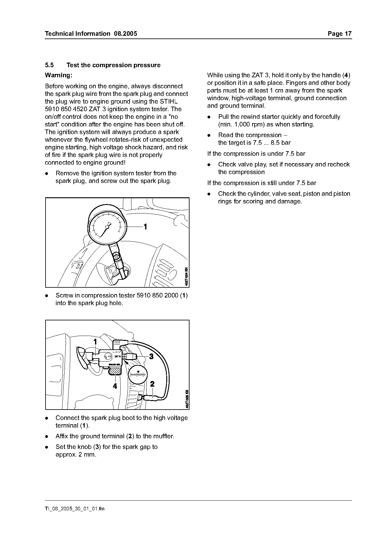
5.5       Test the compression pressure
Warning:                                                While using the ZAT 3, hold it only by the handle (4)
                                                        or position it in a safe place. Fingers and other body
Before working on the engine, always disconnect
                                                        parts must be at least 1 cm away from the spark
the spark plug wire from the spark plug and connect
                                                        window, high-voltage terminal, ground connection
the plug wire to engine ground using the STIHL
                                                        and ground terminal.
5910 850 4520 ZAT 3 ignition system tester. The
on/off control does not keep the engine in a "no        .   Pull the rewind starter quickly and forcefully
start" condition after the engine has been shut off.        (min. 1,000 rpm) as when starting.
The ignition system will always produce a spark
                                                        .   Read the compression –
whenever the flywheel rotates-risk of unexpected
                                                            the target is 7.5 ... 8.5 bar
engine starting, high voltage shock hazard, and risk
of fire if the spark plug wire is not properly          If the compression is under 7.5 bar
connected to engine ground!                             .   Check valve play, set if necessary and recheck
.     Remove the ignition system tester from the            the compression
      spark plug, and screw out the spark plug.         If the compression is still under 7.5 bar
                                                        .   Check the cylinder, valve seat, piston and piston
                                                            rings for scoring and damage.

.     Screw in compression tester 5910 850 2000 (1)
      into the spark plug hole.

.     Connect the spark plug boot to the high voltage
      terminal (1).
.     Affix the ground terminal (2) to the muffler.
.     Set the knob (3) for the spark gap to
      approx. 2 mm.

TI_08_2005_30_01_01.fm
Page 18 of 22
Text of page 18 — search, copy, screen readers
Page 18                                                                      Technical Information 08.2005

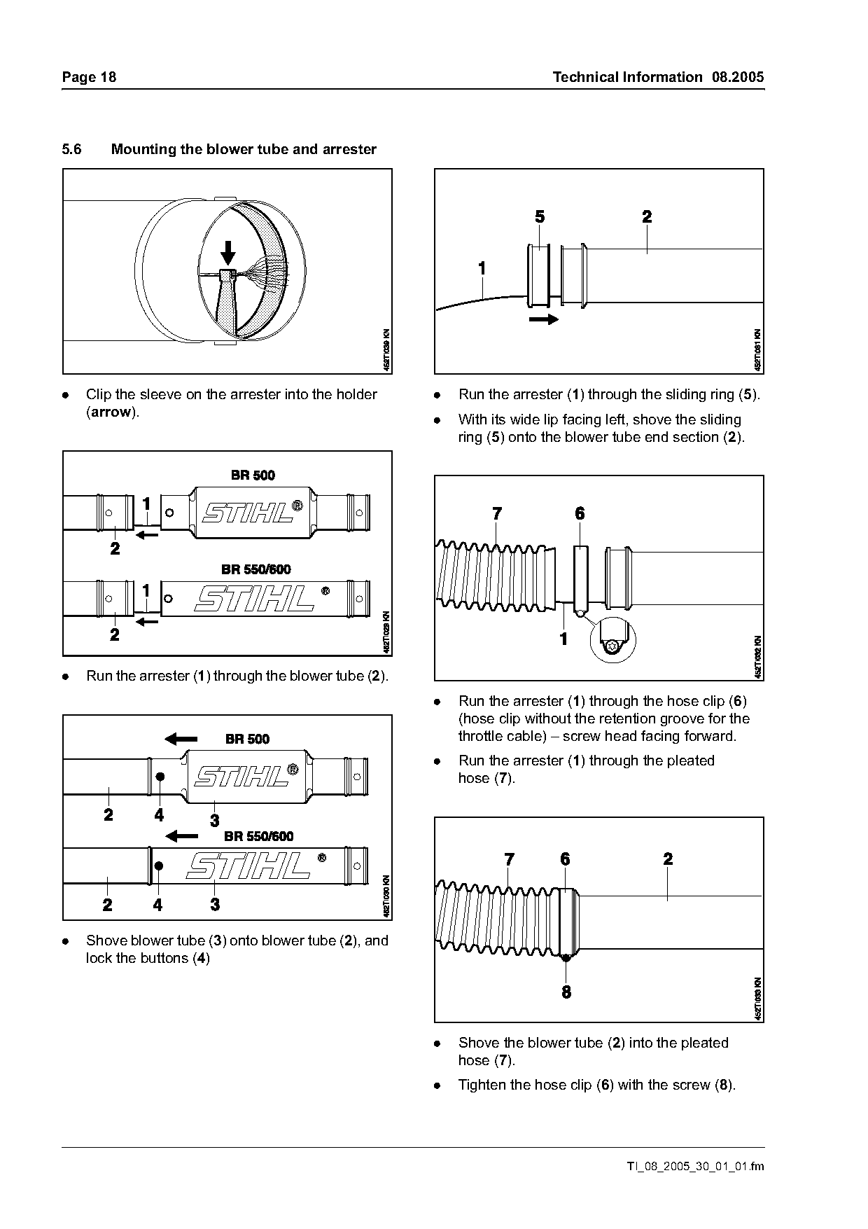
5.6       Mounting the blower tube and arrester

.     Clip the sleeve on the arrester into the holder     .   Run the arrester (1) through the sliding ring (5).
      (arrow).
                                                          .   With its wide lip facing left, shove the sliding
                                                              ring (5) onto the blower tube end section (2).

.     Run the arrester (1) through the blower tube (2).
                                                          .   Run the arrester (1) through the hose clip (6)
                                                              (hose clip without the retention groove for the
                                                              throttle cable) – screw head facing forward.
                                                          .   Run the arrester (1) through the pleated
                                                              hose (7).

.     Shove blower tube (3) onto blower tube (2), and
      lock the buttons (4)

                                                          .   Shove the blower tube (2) into the pleated
                                                              hose (7).
                                                          .   Tighten the hose clip (6) with the screw (8).

                                                                                          TI_08_2005_30_01_01.fm
Page 19 of 22
Text of page 19 — search, copy, screen readers
Technical Information 08.2005                                                                        Page 19

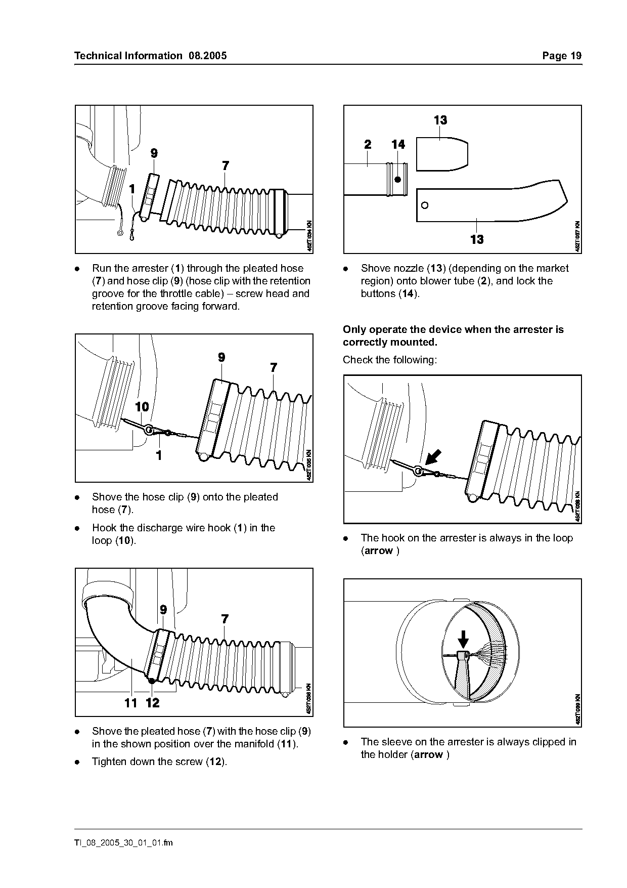
.   Run the arrester (1) through the pleated hose         .   Shove nozzle (13) (depending on the market
    (7) and hose clip (9) (hose clip with the retention       region) onto blower tube (2), and lock the
    groove for the throttle cable) – screw head and           buttons (14).
    retention groove facing forward.

                                                          Only operate the device when the arrester is
                                                          correctly mounted.
                                                          Check the following:

.   Shove the hose clip (9) onto the pleated
    hose (7).
.   Hook the discharge wire hook (1) in the
    loop (10).                                            .   The hook on the arrester is always in the loop
                                                              (arrow )

.   Shove the pleated hose (7) with the hose clip (9)
    in the shown position over the manifold (11).         .   The sleeve on the arrester is always clipped in
                                                              the holder (arrow )
.   Tighten down the screw (12).

TI_08_2005_30_01_01.fm
Page 20 of 22
Text of page 20 — search, copy, screen readers
Page 20                                                                        Technical Information 08.2005

5.7       Adjusting the throttle cable                   5.8       Install tank vent
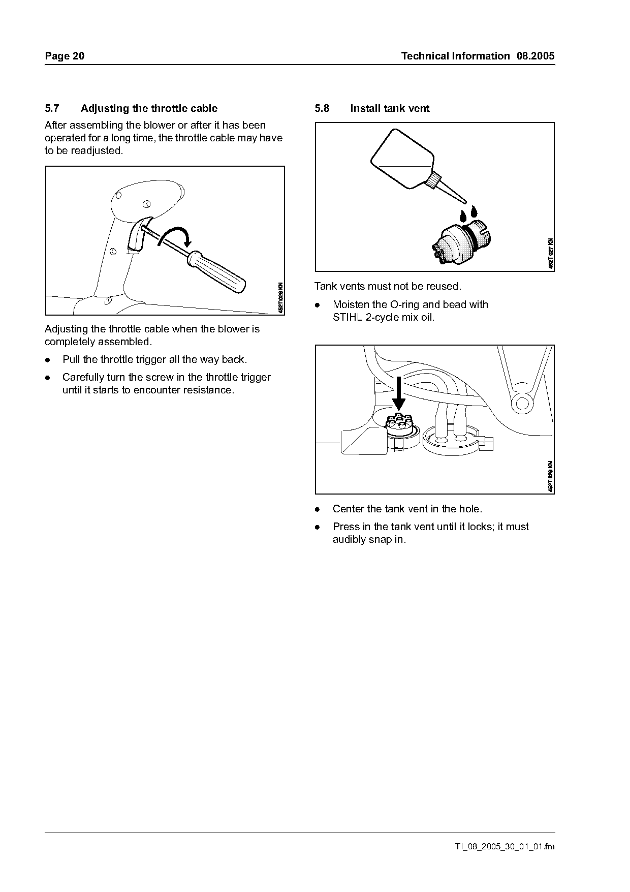
After assembling the blower or after it has been
operated for a long time, the throttle cable may have
to be readjusted.

                                                         Tank vents must not be reused.
                                                         .     Moisten the O-ring and bead with
                                                               STIHL 2-cycle mix oil.
Adjusting the throttle cable when the blower is
completely assembled.
.     Pull the throttle trigger all the way back.
.     Carefully turn the screw in the throttle trigger
      until it starts to encounter resistance.

                                                         .     Center the tank vent in the hole.
                                                         .     Press in the tank vent until it locks; it must
                                                               audibly snap in.

                                                                                           TI_08_2005_30_01_01.fm
Page 21 of 22
Text of page 21 — search, copy, screen readers
Technical Information 08.2005                                                                          Page 21

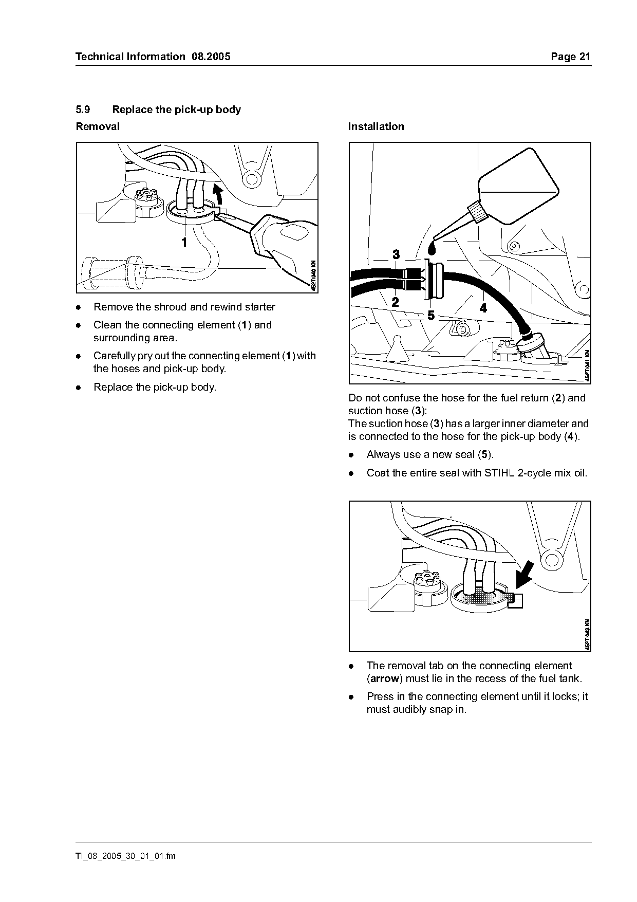
5.9       Replace the pick-up body
Removal                                                   Installation

.     Remove the shroud and rewind starter
.     Clean the connecting element (1) and
      surrounding area.
.     Carefully pry out the connecting element (1) with
      the hoses and pick-up body.
.     Replace the pick-up body.
                                                          Do not confuse the hose for the fuel return (2) and
                                                          suction hose (3):
                                                          The suction hose (3) has a larger inner diameter and
                                                          is connected to the hose for the pick-up body (4).
                                                          .   Always use a new seal (5).
                                                          .   Coat the entire seal with STIHL 2-cycle mix oil.

                                                          .   The removal tab on the connecting element
                                                              (arrow) must lie in the recess of the fuel tank.
                                                          .   Press in the connecting element until it locks; it
                                                              must audibly snap in.

TI_08_2005_30_01_01.fm
Page 22 of 22
Text of page 22 — search, copy, screen readers
Page 22                                                                  Technical Information 08.2005

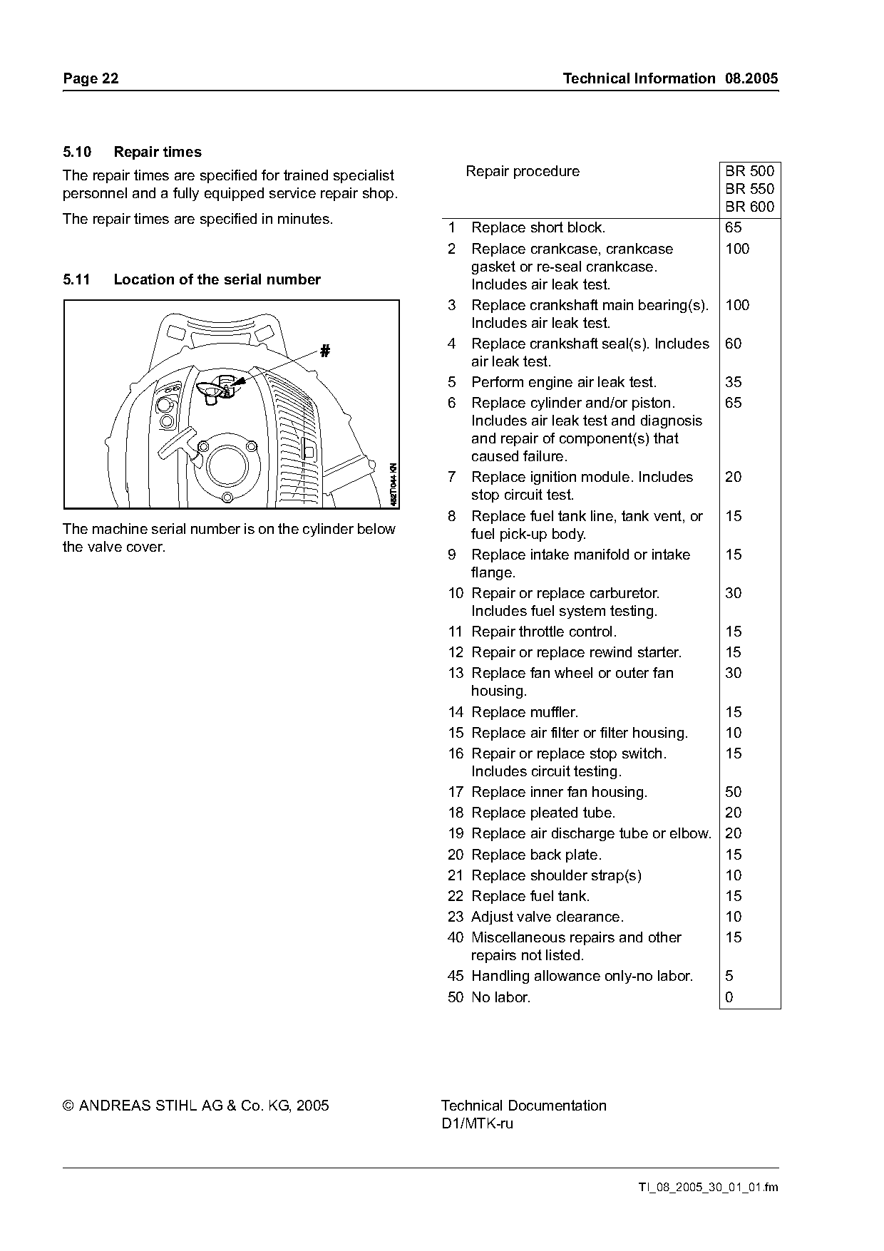
5.10   Repair times
The repair times are specified for trained specialist       Repair procedure                       BR 500
personnel and a fully equipped service repair shop.                                                BR 550
                                                                                                   BR 600
The repair times are specified in minutes.
                                                        1  Replace short block.                    65
                                                        2  Replace crankcase, crankcase            100
                                                           gasket or re-seal crankcase.
5.11   Location of the serial number                       Includes air leak test.
                                                        3 Replace crankshaft main bearing(s).      100
                                                           Includes air leak test.
                                                        4 Replace crankshaft seal(s). Includes     60
                                                           air leak test.
                                                        5 Perform engine air leak test.            35
                                                        6 Replace cylinder and/or piston.          65
                                                           Includes air leak test and diagnosis
                                                           and repair of component(s) that
                                                           caused failure.
                                                        7 Replace ignition module. Includes        20
                                                           stop circuit test.
                                                        8 Replace fuel tank line, tank vent, or    15
The machine serial number is on the cylinder below         fuel pick-up body.
the valve cover.                                        9 Replace intake manifold or intake        15
                                                           flange.
                                                        10 Repair or replace carburetor.           30
                                                           Includes fuel system testing.
                                                        11 Repair throttle control.                15
                                                        12 Repair or replace rewind starter.       15
                                                        13 Replace fan wheel or outer fan          30
                                                           housing.
                                                        14 Replace muffler.                        15
                                                        15 Replace air filter or filter housing.   10
                                                        16 Repair or replace stop switch.          15
                                                           Includes circuit testing.
                                                        17 Replace inner fan housing.              50
                                                        18 Replace pleated tube.                   20
                                                        19 Replace air discharge tube or elbow.    20
                                                        20 Replace back plate.                     15
                                                        21 Replace shoulder strap(s)               10
                                                        22 Replace fuel tank.                      15
                                                        23 Adjust valve clearance.                 10
                                                        40 Miscellaneous repairs and other         15
                                                           repairs not listed.
                                                        45 Handling allowance only-no labor.       5
                                                        50 No labor.                               0

© ANDREAS STIHL AG & Co. KG, 2005                       Technical Documentation
                                                        D1/MTK-ru

                                                                                     TI_08_2005_30_01_01.fm
Most of these PDFs embed fonts with a shifted character map, so the text above was recovered rather than copied — read it as a faithful but imperfect transcription, and treat the page image above each block as the authority where the two disagree — the figures exist only there, because they are vector drawings that text extraction cannot keep.