Technical Information · issue 10 of 2005
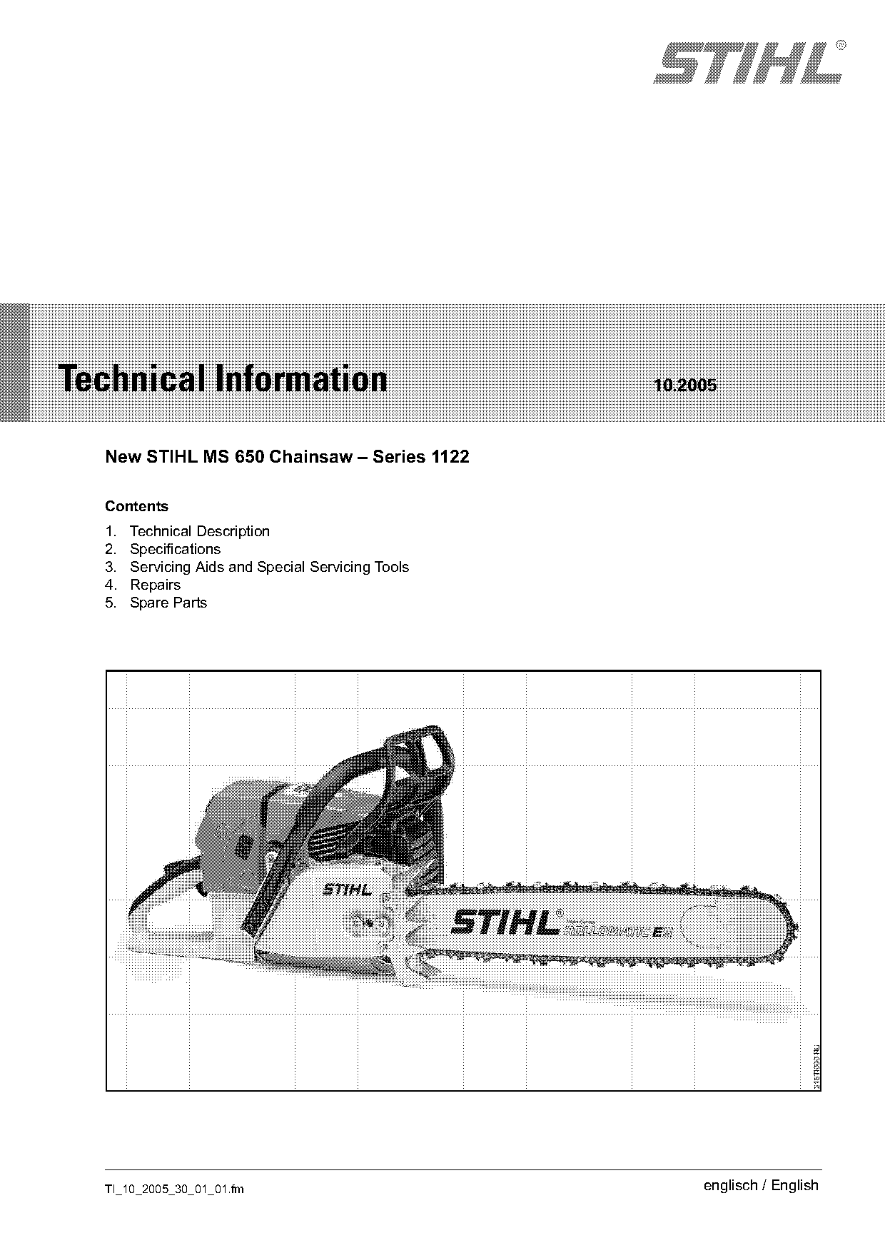
New STIHL MS 650 Chainsaw
IssueTI 10/2005
Engine family 1122
Full text
Page 1 of 7
Text of page 1 — search, copy, screen readers
STIH)

Technical Information                               10.2005

  New STIHL MS 650 Chainsaw – Series 1122

  Contents
  1.   Technical Description
  2.   Specifications
  3.   Servicing Aids and Special Servicing Tools
  4.   Repairs
  5.   Spare Parts

  TI_10_2005_30_01_01.fm                                 englisch / English
Page 2 of 7
Text of page 2 — search, copy, screen readers
Page 2                                                                     Technical Information 10.2005

1.       Technical Description                        2.2     Fuel System

The STIHL MS 650 is a new powerful professional       Carburetor: All position diaphragm carburetor
saw positioned between the MS 460 and MS 660.
The MS 650 has been developed on the basis of the     Standard setting with limiter caps
MS 660. The engine has a displacement of              Low speed screw L          Open 1/4 turn
5.10 cu in (84.9 cm3) and a power output of 4.8 kW                               (no further than stop)
(6.44 hp).
Like the MS 660, it is suitable for wood harvesting   High speed screw H         Open 3/4 turn
operations and cutting work in big timber.                                       (no further than stop)

2.       Specifications
                                                      Basic setting without limiter caps
2.1      Engine                                       Low speed screw L          Open 1 full turn
STIHL single cylinder two-stroke engine
                                                      High speed screw H         Open 1 full turn
Displacement:                 5.10 cu in
                              (84.9 cm3)
Bore:                         2.05 in (52 mm)
Stroke:                       1.57 in (40 mm)         Fuel tank capacity:        1.74 US pt (0.825 l)
Engine power to ISO 7293:     6.44 hp (4.8 kW)
Idle speed:                   2,500 rpm
Max. permissible engine                               Fuel Mix
speed with bar and chain:     13,500 rpm              Uses the same fuel mixture as all other STIHL
Weight without cutting                                two-stroke engines.
attachment:                   16.1 lb (7.3 kg)
                                                      2.3     Ignition System
                                                      Ignition module:           Electronic
                                                      Spark plug                 NGK BPMR 7 A
                                                      (suppressed):              Bosch WSR 6 F
                                                      Electrode gap:             0.020 in (0.5 mm)

                                                      2.4     Chain Lubrication
                                                      Oil pump:                  Fully automatic, speed-
                                                                                 controlled pump with
                                                                                 rotary piston. Adjustable
                                                                                 oil flow control
                                                      Oil tank capacity:         0.76 US pt (0.360 l)

                                                                                     TI_10_2005_30_01_01.fm
Page 3 of 7
Text of page 3 — search, copy, screen readers
Technical Information 10.2005                                                                            Page 3

2.5    Cutting Attachment
Guide bar:                 Rollomatic, Duromatic          Chain sprocket:            7-tooth 3/8“
Bar lengths:               16, 18, 20, 24, 30, 32 and                                (spur sprocket)
                           36 in
Oilomatic saw chain:       Rapid Micro,                                              7-tooth 3/8“
                           Rapid Super,                                              (rim sprocket)
                           Rapid Super C,
                           Rapid Super C3,                                           8-tooth 3/8“
                           Rapid Micro 2                                             (rim sprocket)
Chain pitch:               3/8"
                                                                                     7-tooth .404“
Drive link gauge:          .050“ (1.3 mm) and
                                                                                     (rim sprocket)
                           .063“ (1.6 mm)

3.     Servicing Aids and Special
       Servicing Tools

3.1    Servicing Aids

Part Name                       Part No.         Application
Carburetor parts kit            1122 007 1060    Servicing the carburetor
Lubricating grease              0781 120 1111    Oil seals, oil pump drive, chain sprocket bearing, chain
(225 g tube)                                     tensioner, sliding and bearing points on throttle trigger, brake
                                                 lever and interlock lever
Standard commercial solvent-                     Cleaning crankshaft stub and flywheel taper
based degreasant containing
no chlorinated or
halogenated hydrocarbons

3.2    Special Servicing Tools
No new special servicing tools are required for the
MS 650.

3.3    Special Accessories for Users

Part Name                       Part No.         Application
Cover plate kit                 1122 084 8207    Helps prevent snow being sucked into machine in winter
                                                 conditions (temperatures below 20°F)

TI_10_2005_30_01_01.fm
Page 4 of 7
Text of page 4 — search, copy, screen readers
Page 4                                                                                  Technical Information 10.2005

4.        Repairs                                                    4.2.1   Construction

If the saw is started up in the course of repairs, it is
essential to observe all country-specific safety
regulations and the safety precautions outlined in
the instruction manual.

4.1       Carburetor                                                                                       3
                                                                                                                  1
The carburetor comes from the factory with a
standard setting.
This setting is designed to provide an optimum fuel-

                                                                                                                       178TI006 KN
air mixture under most operating conditions.
                                                                                            4        2

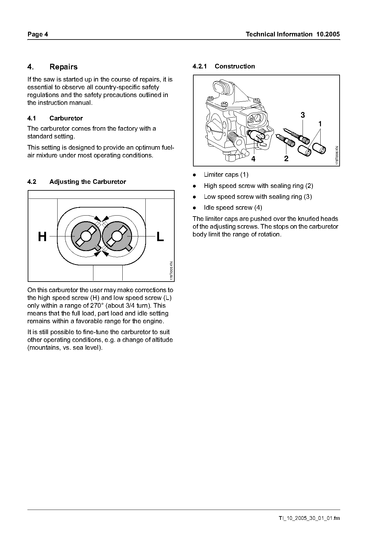
                                                                     .   Limiter caps (1)
4.2       Adjusting the Carburetor
                                                                     .   High speed screw with sealing ring (2)
                                                                     .   Low speed screw with sealing ring (3)
                                                                     .   Idle speed screw (4)
                                                                     The limiter caps are pushed over the knurled heads
                                                                     of the adjusting screws. The stops on the carburetor
                                                                     body limit the range of rotation.
      H                                          L
                                                       178TI005 KN

On this carburetor the user may make corrections to
the high speed screw (H) and low speed screw (L)
only within a range of 270° (about 3/4 turn). This
means that the full load, part load and idle setting
remains within a favorable range for the engine.
It is still possible to fine-tune the carburetor to suit
other operating conditions, e.g. a change of altitude
(mountains, vs. sea level).

                                                                                                   TI_10_2005_30_01_01.fm
Page 5 of 7
Text of page 5 — search, copy, screen readers
Technical Information 10.2005                                                                                        Page 5

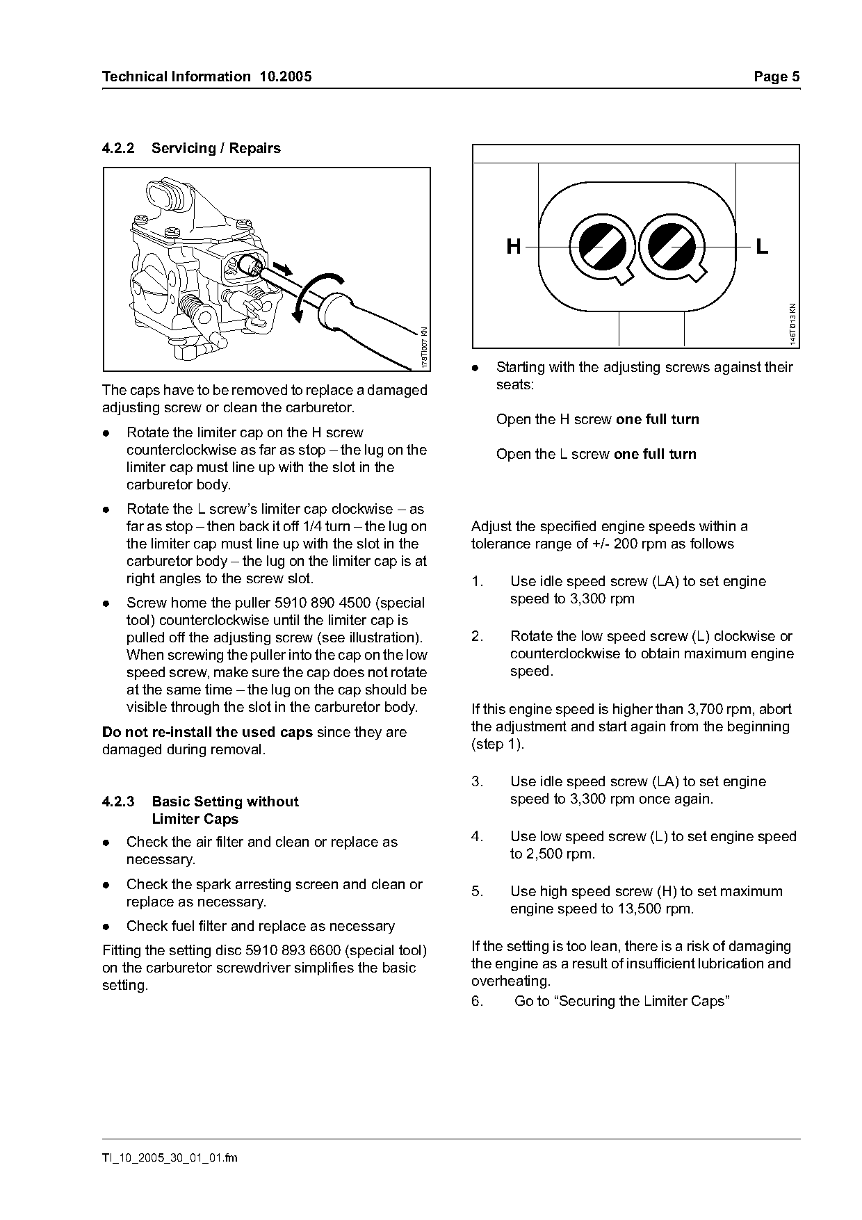
4.2.2   Servicing / Repairs

                                                                           H                                         L

                                                                                                                           146TI013 KN
                                                       178TI007 KN
                                                                     .    Starting with the adjusting screws against their
The caps have to be removed to replace a damaged                          seats:
adjusting screw or clean the carburetor.
                                                                          Open the H screw one full turn
.   Rotate the limiter cap on the H screw
    counterclockwise as far as stop – the lug on the                      Open the L screw one full turn
    limiter cap must line up with the slot in the
    carburetor body.
.   Rotate the L screw’s limiter cap clockwise – as
    far as stop – then back it off 1/4 turn – the lug on             Adjust the specified engine speeds within a
    the limiter cap must line up with the slot in the                tolerance range of +/- 200 rpm as follows
    carburetor body – the lug on the limiter cap is at
    right angles to the screw slot.                                  1.     Use idle speed screw (LA) to set engine
.   Screw home the puller 5910 890 4500 (special                            speed to 3,300 rpm
    tool) counterclockwise until the limiter cap is
    pulled off the adjusting screw (see illustration).               2.     Rotate the low speed screw (L) clockwise or
    When screwing the puller into the cap on the low                        counterclockwise to obtain maximum engine
    speed screw, make sure the cap does not rotate                          speed.
    at the same time – the lug on the cap should be
    visible through the slot in the carburetor body.                 If this engine speed is higher than 3,700 rpm, abort
Do not re-install the used caps since they are                       the adjustment and start again from the beginning
damaged during removal.                                              (step 1).

                                                                     3.     Use idle speed screw (LA) to set engine
4.2.3   Basic Setting without                                               speed to 3,300 rpm once again.
        Limiter Caps
.   Check the air filter and clean or replace as                     4.     Use low speed screw (L) to set engine speed
    necessary.                                                              to 2,500 rpm.

.   Check the spark arresting screen and clean or
                                                                     5.     Use high speed screw (H) to set maximum
    replace as necessary.
                                                                            engine speed to 13,500 rpm.
.   Check fuel filter and replace as necessary
Fitting the setting disc 5910 893 6600 (special tool)                If the setting is too lean, there is a risk of damaging
on the carburetor screwdriver simplifies the basic                   the engine as a result of insufficient lubrication and
setting.                                                             overheating.
                                                                     6.      Go to “Securing the Limiter Caps”

TI_10_2005_30_01_01.fm
Page 6 of 7
Text of page 6 — search, copy, screen readers
Page 6                                                                        Technical Information 10.2005

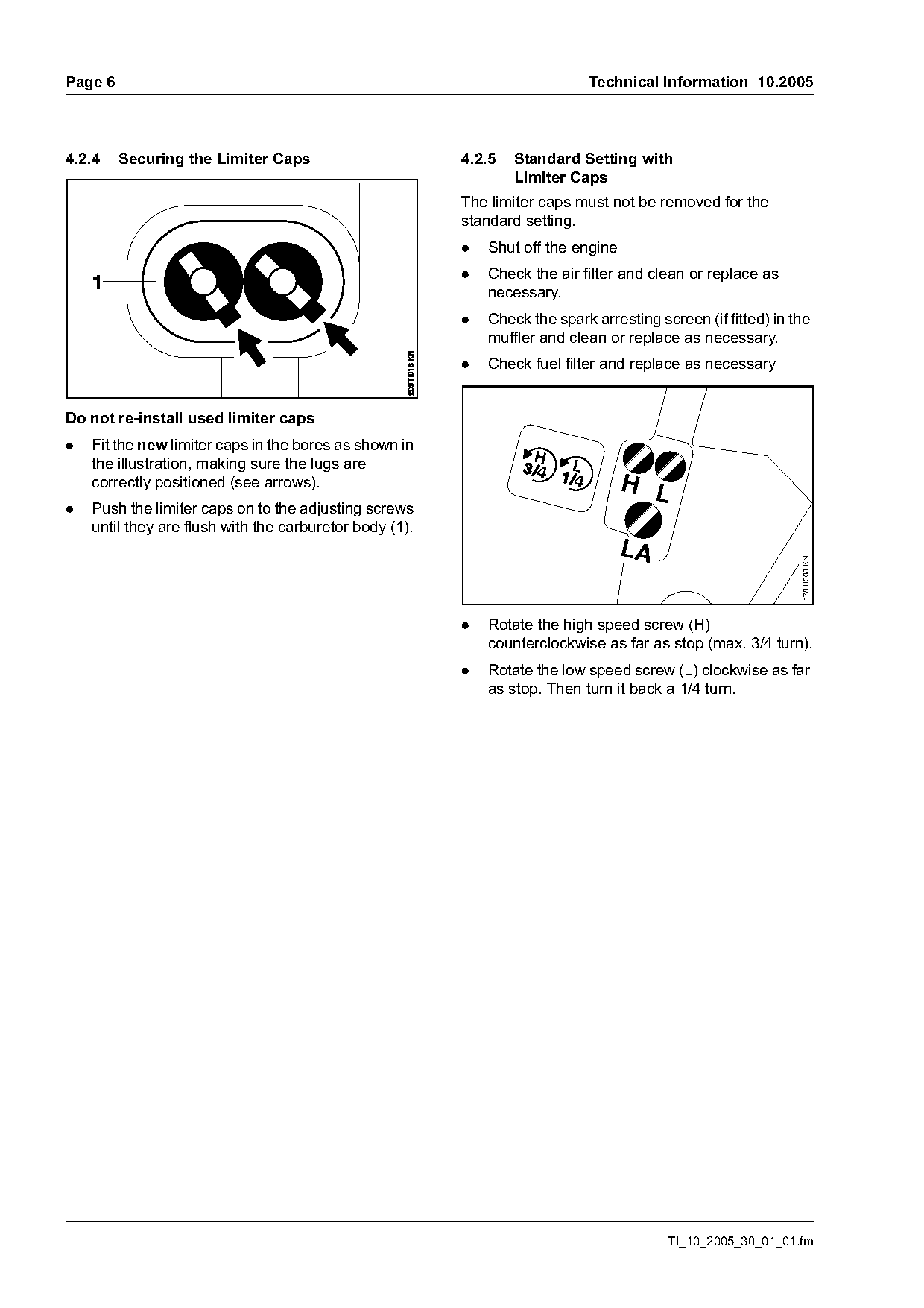
4.2.4    Securing the Limiter Caps                       4.2.5   Standard Setting with
                                                                 Limiter Caps
                                                         The limiter caps must not be removed for the
                                                         standard setting.
                                                         .   Shut off the engine
                                                         .   Check the air filter and clean or replace as
                                                             necessary.
                                                         .   Check the spark arresting screen (if fitted) in the
                                                             muffler and clean or replace as necessary.
                                                         .   Check fuel filter and replace as necessary

Do not re-install used limiter caps
.   Fit the new limiter caps in the bores as shown in
    the illustration, making sure the lugs are                      H
    correctly positioned (see arrows).                                             H L
.   Push the limiter caps on to the adjusting screws
    until they are flush with the carburetor body (1).
                                                                                   LA

                                                                                                              178TI008 KN
                                                         .   Rotate the high speed screw (H)
                                                             counterclockwise as far as stop (max. 3/4 turn).
                                                         .   Rotate the low speed screw (L) clockwise as far
                                                             as stop. Then turn it back a 1/4 turn.

                                                                                         TI_10_2005_30_01_01.fm
Page 7 of 7
Text of page 7 — search, copy, screen readers
Technical Information 10.2005                                                      Page 7

4.3     Repair Times
The specified repair times assume that the work is
performed by trained personnel in a properly
equipped service workshop.
The same repair times from the MS 660 timetable
can be used for the MS 650.

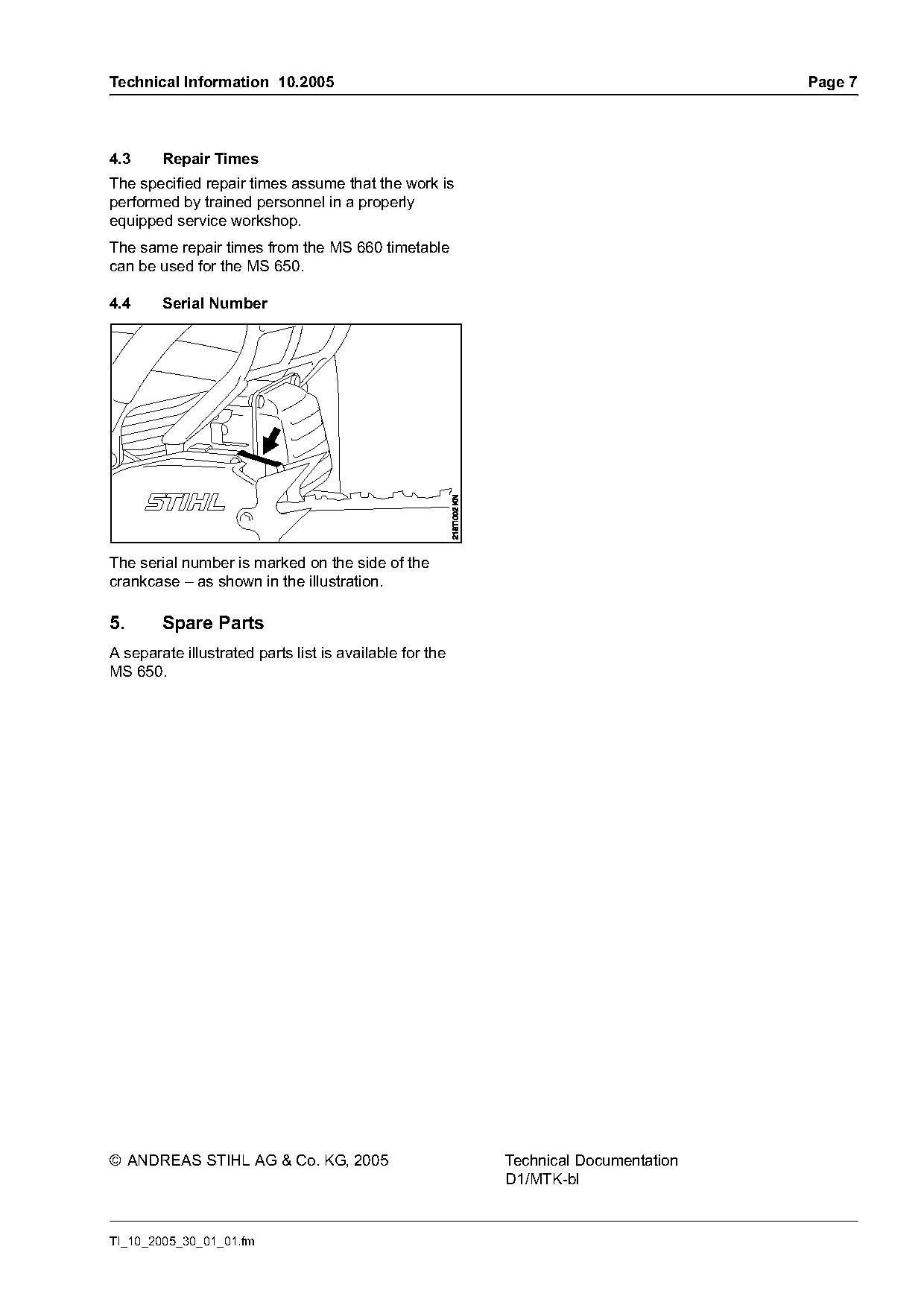
4.4     Serial Number

The serial number is marked on the side of the
crankcase – as shown in the illustration.

5.      Spare Parts
A separate illustrated parts list is available for the
MS 650.

© ANDREAS STIHL AG & Co. KG, 2005                        Technical Documentation
                                                         D1/MTK-bl

TI_10_2005_30_01_01.fm
Most of these PDFs embed fonts with a shifted character map, so the text above was recovered rather than copied — read it as a faithful but imperfect transcription, and treat the page image above each block as the authority where the two disagree — the figures exist only there, because they are vector drawings that text extraction cannot keep.