Technical Information · issue 17 of 2005
New STIHL SP Special Harvester
IssueTI 17/2005
Full text
Page 1 of 9
Text of page 1 — search, copy, screen readers
STIH)

Technical Information                                          17.2005

  New STIHL SP Special Harvester                        – Series 4231

  Contents
  1.   Technical Description
  2.   Specifications
  3.   Approved Basic Power Tools
  4.   Mounting the Attachment
  5.   User Instructions
  6.   Accessories
  7.   Repairs
  8.   Spare Parts

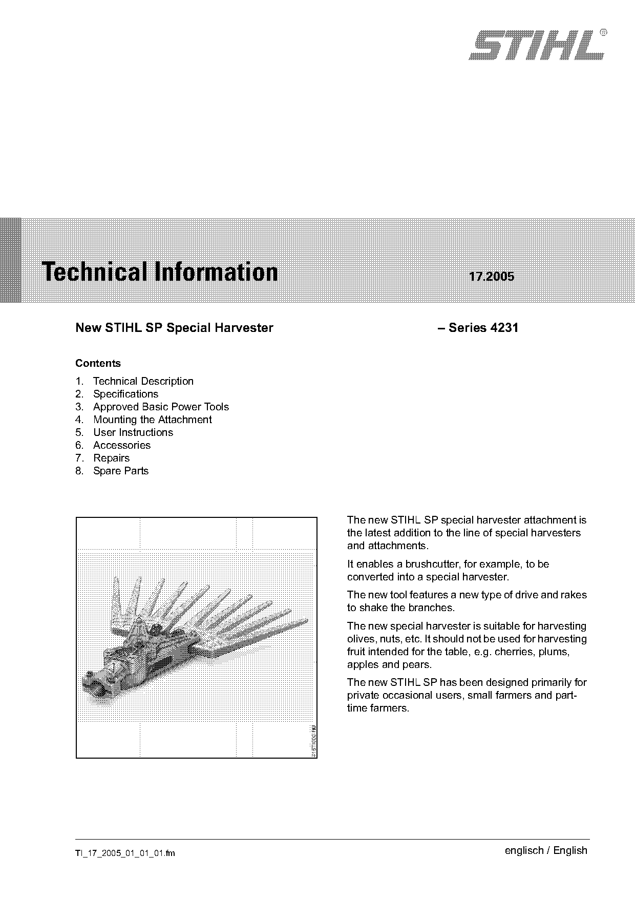
                                    The new STIHL SP special harvester attachment is
                                    the latest addition to the line of special harvesters
                                    and attachments.
                                    It enables a brushcutter, for example, to be
                                    converted into a special harvester.
                                    The new tool features a new type of drive and rakes
                                    to shake the branches.
                                    The new special harvester is suitable for harvesting
                                    olives, nuts, etc. It should not be used for harvesting
                                    fruit intended for the table, e.g. cherries, plums,
                                    apples and pears.
                                    The new STIHL SP has been designed primarily for
                                    private occasional users, small farmers and part-
                                    time farmers.

  TI_17_2005_01_01_01.fm                                                englisch / English
Page 2 of 9
Text of page 2 — search, copy, screen readers
Page 2                                                                                Technical Information 17.2005

Thanks to its low weight – see “Specifications” – and       2.3       Gearhead
a handle hose that can be moved along the power
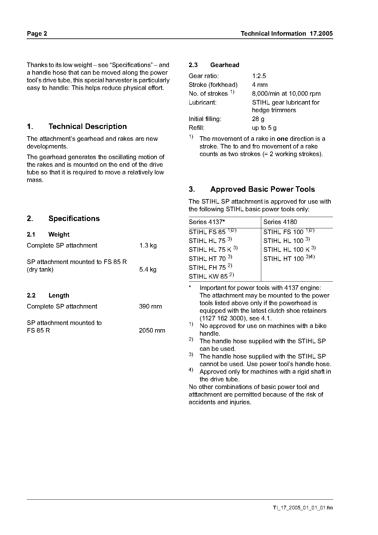
                                                            Gear ratio:                  1:2.5
tool’s drive tube, this special harvester is particularly
                                                            Stroke (forkhead)            4 mm
easy to handle: This helps reduce physical effort.
                                                            No. of strokes 1)            8,000/min at 10,000 rpm
                                                            Lubricant:                   STIHL gear lubricant for
                                                                                         hedge trimmers
                                                            Initial filling:             28 g
1.       Technical Description                              Refill:                      up to 5 g
                                                            1)
The attachment’s gearhead and rakes are new                       The movement of a rake in one direction is a
developments.                                                     stroke. The to and fro movement of a rake
                                                                  counts as two strokes (= 2 working strokes).
The gearhead generates the oscillating motion of
the rakes and is mounted on the end of the drive
tube so that it is required to move a relatively low
mass.
                                                            3.        Approved Basic Power Tools
                                                            The STIHL SP attachment is approved for use with
                                                            the following STIHL basic power tools only:
2.       Specifications                                     Series 4137*                     Series 4180
                                                                               1)2)
2.1      Weight                                             STIHL FS 85                      STIHL FS 100 1)2)
                                                            STIHL HL 75 3)                   STIHL HL 100 3)
Complete SP attachment                      1.3 kg
                                                            STIHL HL 75 K 3)                 STIHL HL 100 K 3)
SP attachment mounted to FS 85 R                            STIHL HT 70 3)                   STIHL HT 100 3)4)
(dry tank)                                  5.4 kg          STIHL FH 75 2)
                                                            STIHL KW 85 2)
                                                            *    Important for power tools with 4137 engine:
2.2      Length                                                  The attachment may be mounted to the power
                                                                 tools listed above only if the powerhead is
Complete SP attachment                      390 mm
                                                                 equipped with the latest clutch shoe retainers
                                                                 (1127 162 3000), see 4.1.
SP attachment mounted to                                    1) No approved for use on machines with a bike
FS 85 R                                     2050 mm
                                                                 handle.
                                                            2) The handle hose supplied with the STIHL SP
                                                                 can be used.
                                                            3) The handle hose supplied with the STIHL SP

                                                                 cannot be used. Use power tool’s handle hose.
                                                            4)
                                                                 Approved only for machines with a rigid shaft in
                                                                 the drive tube.
                                                            No other combinations of basic power tool and
                                                            atttachment are permitted because of the risk of
                                                            accidents and injuries.

                                                                                                TI_17_2005_01_01_01.fm
Page 3 of 9
Text of page 3 — search, copy, screen readers
Technical Information 17.2005                                                                         Page 3

4.     Mounting the Attachment                         4.2     General Notes
                                                       The following instructions refer to mounting the
4.1    Replacing the Retainers (only on                STIHL SP to an FS 85 R brushcutter.
       machines with a Series 4137 powerhead)
                                                       There is no loop handle on HT basic power tools
                                                       (4.5 and 4.6).
                                                       The handle hose included with the SP cannot be
                                                       fitted on HL basic power tools becuase they are
                                                       already equipped with a handle hose (4.7).

                                                       4.3     Vibration Data
                                                       Basic power tool:                 FS 85 R
                                                       Attachment:                       Rakes

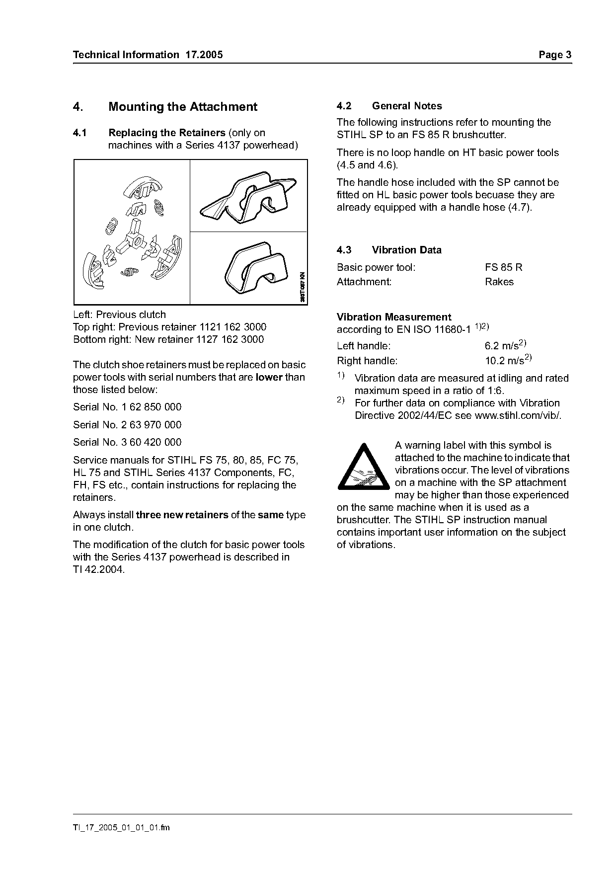
Left: Previous clutch                                  Vibration Measurement
Top right: Previous retainer 1121 162 3000             according to EN ISO 11680-1 1)2)
Bottom right: New retainer 1127 162 3000
                                                       Left handle:                      6.2 m/s2)
The clutch shoe retainers must be replaced on basic    Right handle:                     10.2 m/s2)
power tools with serial numbers that are lower than    1)
                                                          Vibration data are measured at idling and rated
those listed below:                                       maximum speed in a ratio of 1:6.
                                                       2)
Serial No. 1 62 850 000                                   For further data on compliance with Vibration
                                                          Directive 2002/44/EC see www.stihl.com/vib/.
Serial No. 2 63 970 000
Serial No. 3 60 420 000                                              A warning label with this symbol is
Service manuals for STIHL FS 75, 80, 85, FC 75,                      attached to the machine to indicate that
HL 75 and STIHL Series 4137 Components, FC,                          vibrations occur. The level of vibrations
FH, FS etc., contain instructions for replacing the                  on a machine with the SP attachment
retainers.                                                           may be higher than those experienced
                                                       on the same machine when it is used as a
Always install three new retainers of the same type
                                                       brushcutter. The STIHL SP instruction manual
in one clutch.
                                                       contains important user information on the subject
The modification of the clutch for basic power tools   of vibrations.
with the Series 4137 powerhead is described in
TI 42.2004.

TI_17_2005_01_01_01.fm
Page 4 of 9
Text of page 4 — search, copy, screen readers
Page 4                                                                         Technical Information 17.2005

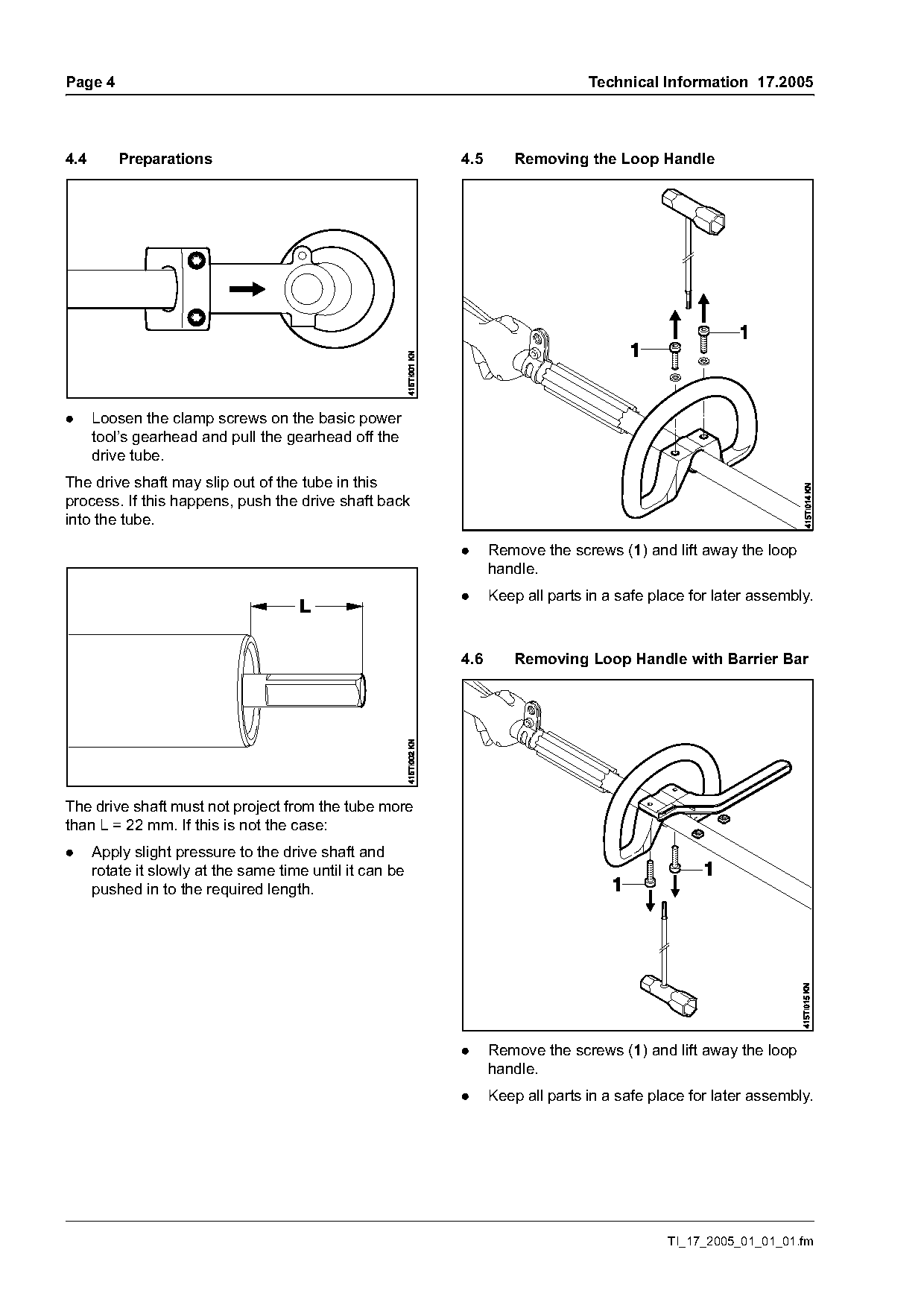
4.4       Preparations                                    4.5       Removing the Loop Handle

.     Loosen the clamp screws on the basic power
      tool’s gearhead and pull the gearhead off the
      drive tube.
The drive shaft may slip out of the tube in this
process. If this happens, push the drive shaft back
into the tube.

                                                          .     Remove the screws (1) and lift away the loop
                                                                handle.
                                                          .     Keep all parts in a safe place for later assembly.

                                                          4.6       Removing Loop Handle with Barrier Bar

The drive shaft must not project from the tube more
than L = 22 mm. If this is not the case:
.     Apply slight pressure to the drive shaft and
      rotate it slowly at the same time until it can be
      pushed in to the required length.

                                                          .     Remove the screws (1) and lift away the loop
                                                                handle.
                                                          .     Keep all parts in a safe place for later assembly.

                                                                                           TI_17_2005_01_01_01.fm
Page 5 of 9
Text of page 5 — search, copy, screen readers
Technical Information 17.2005                                                                          Page 5

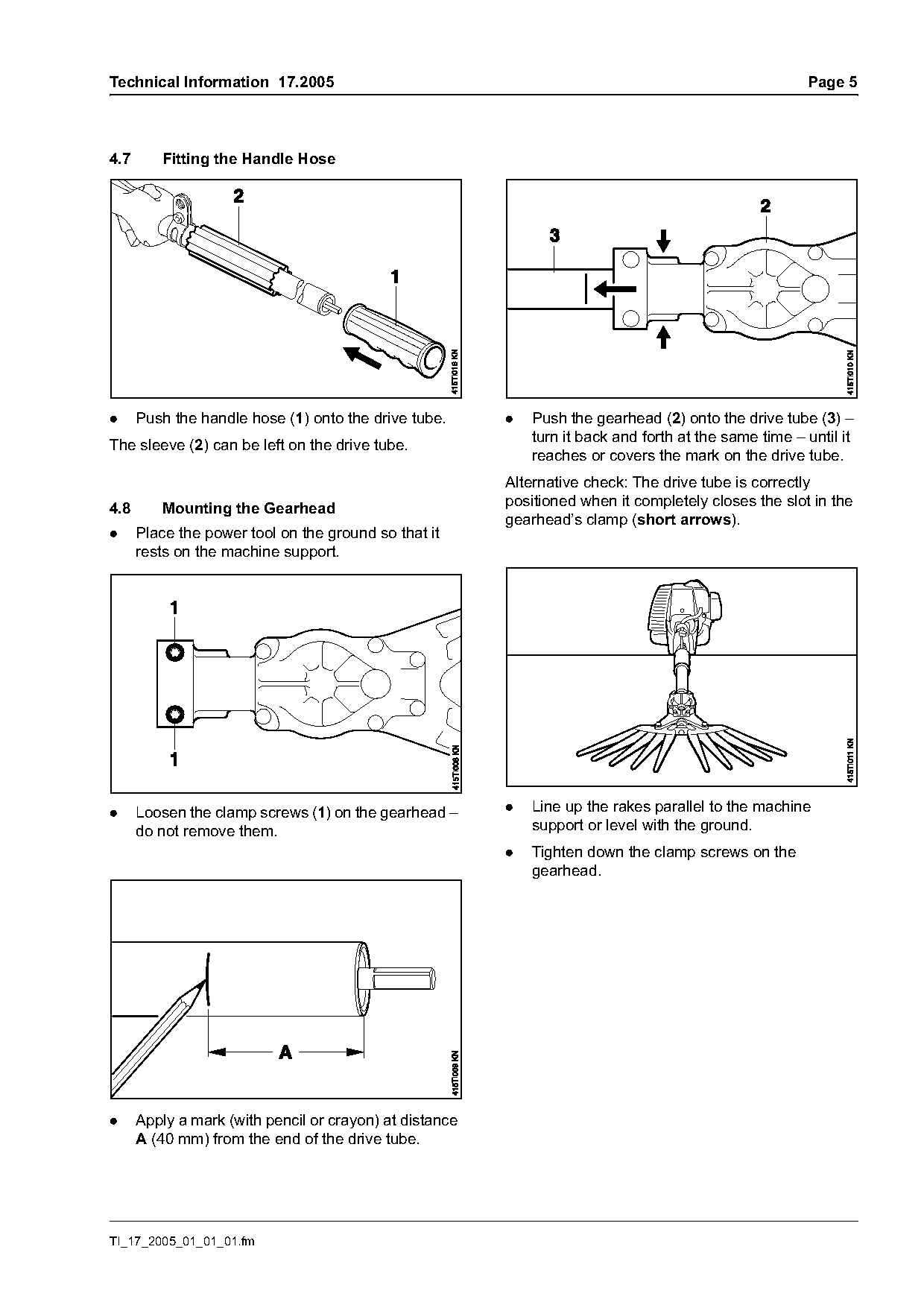
4.7      Fitting the Handle Hose

.     Push the handle hose (1) onto the drive tube.      .   Push the gearhead (2) onto the drive tube (3) –
                                                             turn it back and forth at the same time – until it
The sleeve (2) can be left on the drive tube.
                                                             reaches or covers the mark on the drive tube.
                                                         Alternative check: The drive tube is correctly
                                                         positioned when it completely closes the slot in the
4.8      Mounting the Gearhead
                                                         gearhead’s clamp (short arrows).
.     Place the power tool on the ground so that it
      rests on the machine support.

.     Loosen the clamp screws (1) on the gearhead –      .   Line up the rakes parallel to the machine
      do not remove them.                                    support or level with the ground.
                                                         .   Tighten down the clamp screws on the
                                                             gearhead.

.     Apply a mark (with pencil or crayon) at distance
      A (40 mm) from the end of the drive tube.

TI_17_2005_01_01_01.fm
Page 6 of 9
Text of page 6 — search, copy, screen readers
Page 6                                                                             Technical Information 17.2005

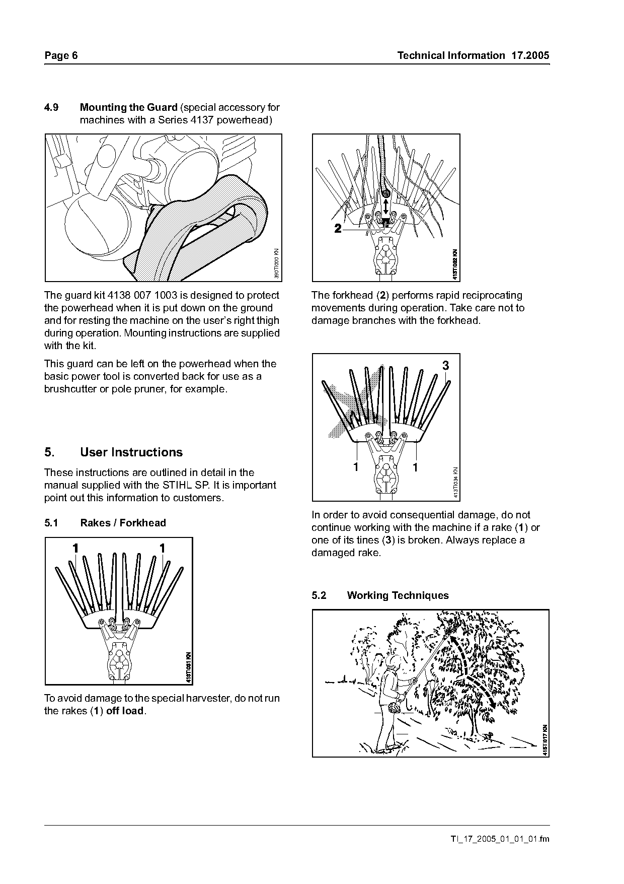
4.9      Mounting the Guard (special accessory for
         machines with a Series 4137 powerhead)

                                                   390TI000 KN

The guard kit 4138 007 1003 is designed to protect               The forkhead (2) performs rapid reciprocating
the powerhead when it is put down on the ground                  movements during operation. Take care not to
and for resting the machine on the user’s right thigh            damage branches with the forkhead.
during operation. Mounting instructions are supplied
with the kit.
This guard can be left on the powerhead when the                                             3
basic power tool is converted back for use as a
brushcutter or pole pruner, for example.

5.       User Instructions
These instructions are outlined in detail in the                         1             1
                                                                                                 413TI034 KN

manual supplied with the STIHL SP. It is important
point out this information to customers.
                                                                 In order to avoid consequential damage, do not
5.1      Rakes / Forkhead                                        continue working with the machine if a rake (1) or
                                                                 one of its tines (3) is broken. Always replace a
                                                                 damaged rake.

                                                                 5.2    Working Techniques

To avoid damage to the special harvester, do not run
the rakes (1) off load.

                                                                                                 TI_17_2005_01_01_01.fm
Page 7 of 9
Text of page 7 — search, copy, screen readers
Technical Information 17.2005                                                                          Page 7

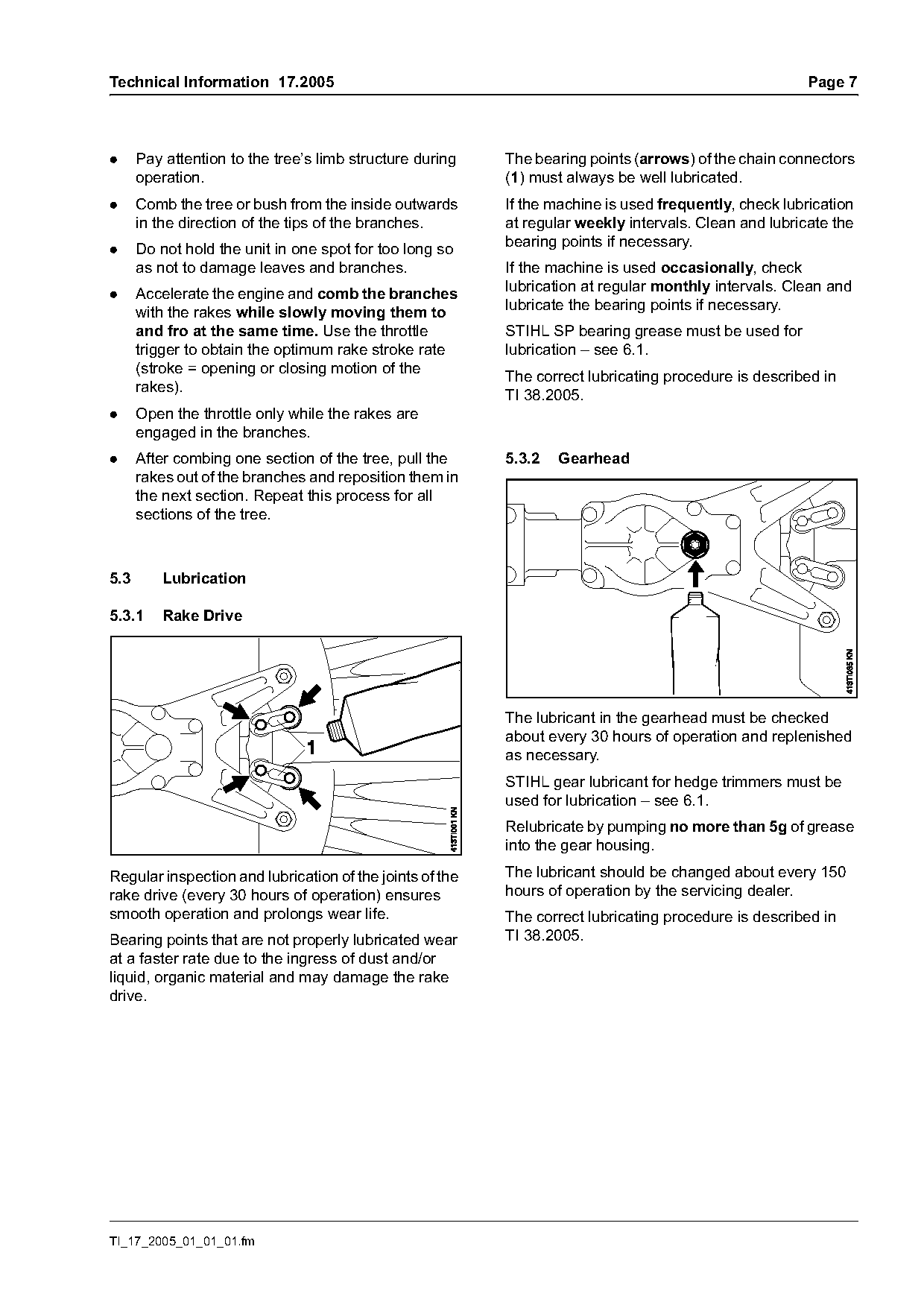
.     Pay attention to the tree’s limb structure during   The bearing points (arrows) of the chain connectors
      operation.                                          (1) must always be well lubricated.
.     Comb the tree or bush from the inside outwards      If the machine is used frequently, check lubrication
      in the direction of the tips of the branches.       at regular weekly intervals. Clean and lubricate the
                                                          bearing points if necessary.
.     Do not hold the unit in one spot for too long so
      as not to damage leaves and branches.               If the machine is used occasionally, check
                                                          lubrication at regular monthly intervals. Clean and
.     Accelerate the engine and comb the branches
                                                          lubricate the bearing points if necessary.
      with the rakes while slowly moving them to
      and fro at the same time. Use the throttle          STIHL SP bearing grease must be used for
      trigger to obtain the optimum rake stroke rate      lubrication – see 6.1.
      (stroke = opening or closing motion of the
                                                          The correct lubricating procedure is described in
      rakes).
                                                          TI 38.2005.
.     Open the throttle only while the rakes are
      engaged in the branches.
.     After combing one section of the tree, pull the     5.3.2   Gearhead
      rakes out of the branches and reposition them in
      the next section. Repeat this process for all
      sections of the tree.

5.3       Lubrication

5.3.1     Rake Drive

                                                          The lubricant in the gearhead must be checked
                                                          about every 30 hours of operation and replenished
                                                          as necessary.
                                                          STIHL gear lubricant for hedge trimmers must be
                                                          used for lubrication – see 6.1.
                                                          Relubricate by pumping no more than 5g of grease
                                                          into the gear housing.

Regular inspection and lubrication of the joints of the   The lubricant should be changed about every 150
rake drive (every 30 hours of operation) ensures          hours of operation by the servicing dealer.
smooth operation and prolongs wear life.                  The correct lubricating procedure is described in
Bearing points that are not properly lubricated wear      TI 38.2005.
at a faster rate due to the ingress of dust and/or
liquid, organic material and may damage the rake
drive.

TI_17_2005_01_01_01.fm
Page 8 of 9
Text of page 8 — search, copy, screen readers
Page 8                                                                       Technical Information 17.2005

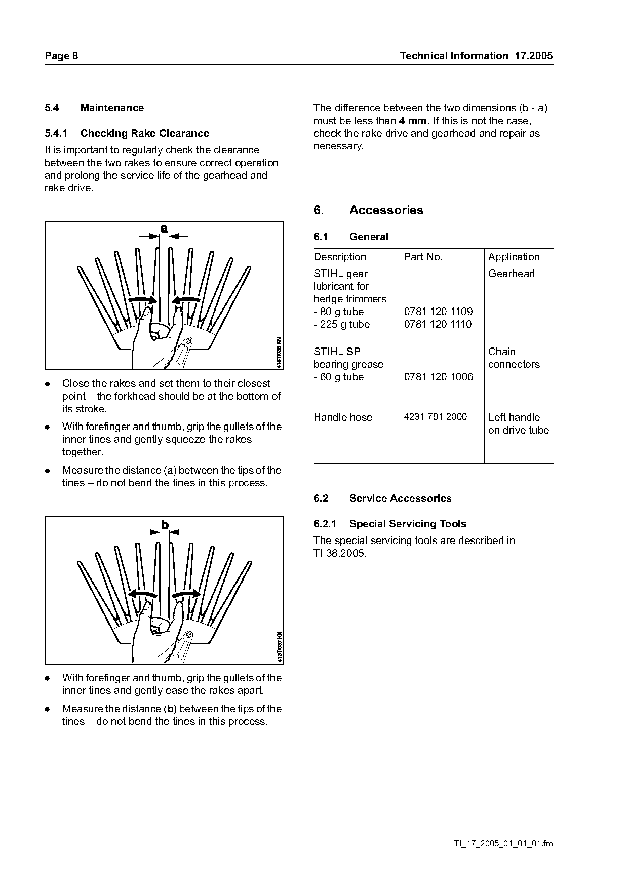
5.4       Maintenance                                      The difference between the two dimensions (b - a)
                                                           must be less than 4 mm. If this is not the case,
5.4.1     Checking Rake Clearance                          check the rake drive and gearhead and repair as
It is important to regularly check the clearance           necessary.
between the two rakes to ensure correct operation
and prolong the service life of the gearhead and
rake drive.

                                                           6.      Accessories

                                                           6.1     General
                                                           Description        Part No.           Application
                                                           STIHL gear                            Gearhead
                                                           lubricant for
                                                           hedge trimmers
                                                           - 80 g tube        0781 120 1109
                                                           - 225 g tube       0781 120 1110

                                                           STIHL SP                              Chain
                                                           bearing grease                        connectors
                                                           - 60 g tube        0781 120 1006
.     Close the rakes and set them to their closest
      point – the forkhead should be at the bottom of
      its stroke.
                                                           Handle hose        4231 791 2000      Left handle
.     With forefinger and thumb, grip the gullets of the                                         on drive tube
      inner tines and gently squeeze the rakes
      together.
.     Measure the distance (a) between the tips of the
      tines – do not bend the tines in this process.
                                                           6.2     Service Accessories

                                                           6.2.1   Special Servicing Tools
                                                           The special servicing tools are described in
                                                           TI 38.2005.

.     With forefinger and thumb, grip the gullets of the
      inner tines and gently ease the rakes apart.
.     Measure the distance (b) between the tips of the
      tines – do not bend the tines in this process.

                                                                                         TI_17_2005_01_01_01.fm
Page 9 of 9
Text of page 9 — search, copy, screen readers
Technical Information 17.2005                                                                       Page 9

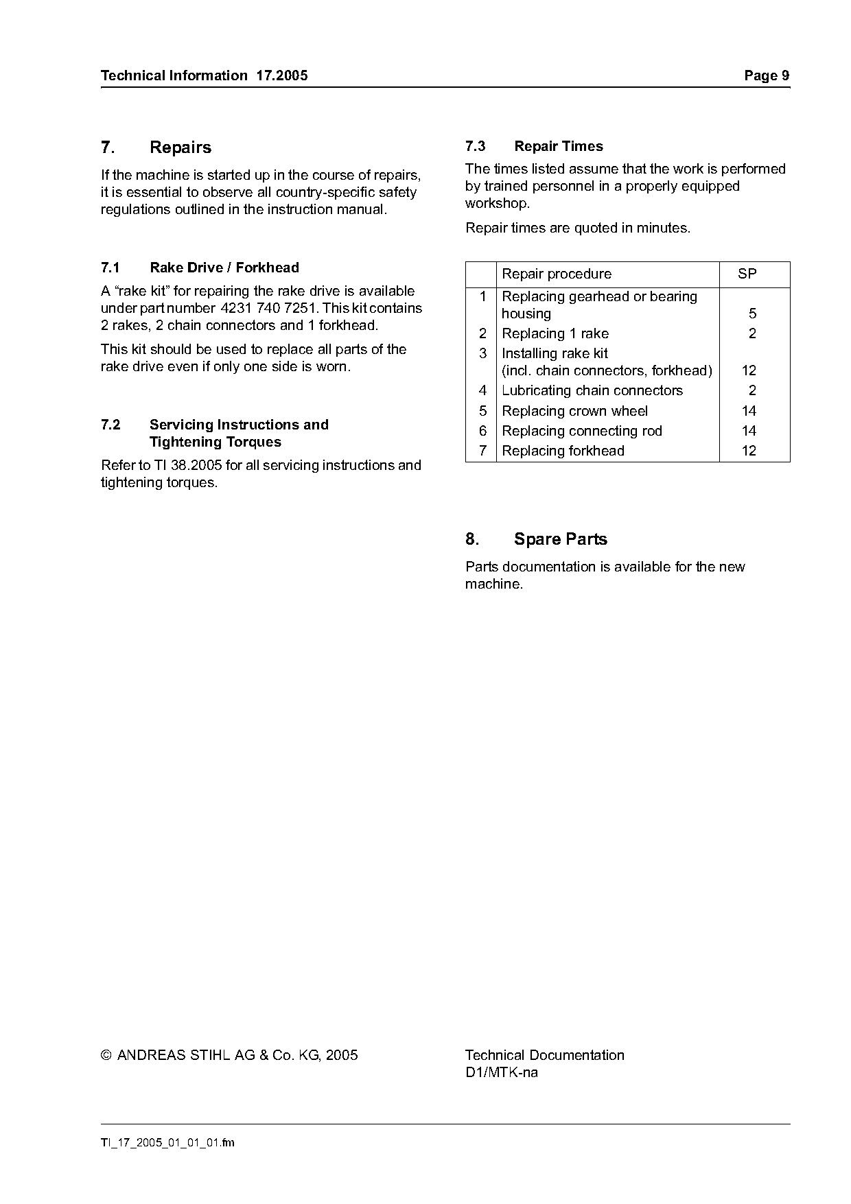
7.      Repairs                                          7.3     Repair Times

If the machine is started up in the course of repairs,   The times listed assume that the work is performed
it is essential to observe all country-specific safety   by trained personnel in a properly equipped
regulations outlined in the instruction manual.          workshop.
                                                         Repair times are quoted in minutes.

7.1     Rake Drive / Forkhead                                  Repair procedure                     SP
A “rake kit” for repairing the rake drive is available     1   Replacing gearhead or bearing
under part number 4231 740 7251. This kit contains             housing                                  5
2 rakes, 2 chain connectors and 1 forkhead.
                                                           2   Replacing 1 rake                         2
This kit should be used to replace all parts of the        3   Installing rake kit
rake drive even if only one side is worn.                      (incl. chain connectors, forkhead)   12
                                                           4   Lubricating chain connectors          2
                                                           5   Replacing crown wheel                14
7.2     Servicing Instructions and                         6   Replacing connecting rod             14
        Tightening Torques
                                                           7   Replacing forkhead                   12
Refer to TI 38.2005 for all servicing instructions and
tightening torques.

                                                         8.      Spare Parts
                                                         Parts documentation is available for the new
                                                         machine.

© ANDREAS STIHL AG & Co. KG, 2005                        Technical Documentation
                                                         D1/MTK-na

TI_17_2005_01_01_01.fm
Most of these PDFs embed fonts with a shifted character map, so the text above was recovered rather than copied — read it as a faithful but imperfect transcription, and treat the page image above each block as the authority where the two disagree — the figures exist only there, because they are vector drawings that text extraction cannot keep.