Technical Information · issue 38 of 2005
Tightening Torques; Rake Drive; Gearhead; Clutch (SP 81 and Basic Power Tools with Series 4137 Engine)
IssueTI 38/2005
Full text
Page 1 of 6
Text of page 1 — search, copy, screen readers
STIH)

Technical Information                                                        38.2005

  Servicing STIHL SP and STIHL SP 81 Special Harvesters – Series 4231

  Contents
  1. Tightening Torques
  2. Rake Drive
     2.1 Rake Drive / Forkhead
     2.2 Chain Connector
     2.3 Rakes
     2.4 Forkhead
  3. Gearhead
     3.1 Disassembling the Gearhead
     3.2 Assembling the Gearhead
  4. Clutch (SP 81 and Basic Power Tools with Series 4137 Engine)
     4.1 Clutch Shoe Retainers

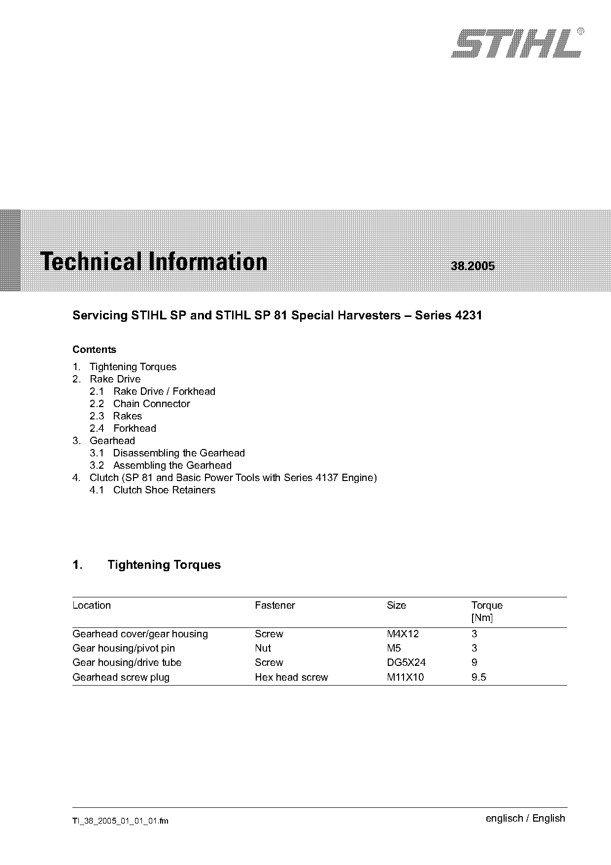
  1.     Tightening Torques

  Location                             Fastener                     Size        Torque
                                                                                [Nm]
  Gearhead cover/gear housing          Screw                        M4X12       3
  Gear housing/pivot pin               Nut                          M5          3
  Gear housing/drive tube              Screw                        DG5X24      9
  Gearhead screw plug                  Hex head screw               M11X10      9.5

  TI_38_2005_01_01_01.fm                                                          englisch / English
Page 2 of 6
Text of page 2 — search, copy, screen readers
Page 2                                                                        Technical Information 38.2005

2.        Rake Drive
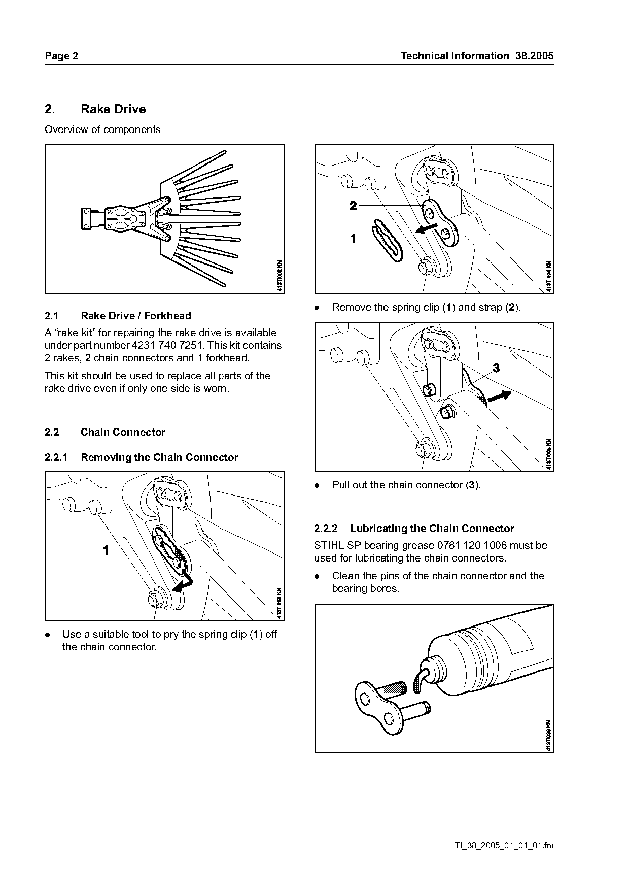
Overview of components

                                                           .   Remove the spring clip (1) and strap (2).
2.1       Rake Drive / Forkhead
A “rake kit” for repairing the rake drive is available
under part number 4231 740 7251. This kit contains
2 rakes, 2 chain connectors and 1 forkhead.
This kit should be used to replace all parts of the
rake drive even if only one side is worn.

2.2       Chain Connector

2.2.1     Removing the Chain Connector

                                                           .   Pull out the chain connector (3).

                                                           2.2.2   Lubricating the Chain Connector
                                                           STIHL SP bearing grease 0781 120 1006 must be
                                                           used for lubricating the chain connectors.
                                                           .   Clean the pins of the chain connector and the
                                                               bearing bores.

.     Use a suitable tool to pry the spring clip (1) off
      the chain connector.

                                                                                          TI_38_2005_01_01_01.fm
Page 3 of 6
Text of page 3 — search, copy, screen readers
Technical Information 38.2005                                                                          Page 3

.     Squeeze the tube of grease to obtain a small      2.3.2    Mounting the Rakes
      quantity of grease.                               Observe the tightening torques in chapter 1.
.     Coat each chain connector pin with SP bearing     .     Install the rakes in the reverse sequence.
      grease.

                                                        2.4      Forkhead
2.2.3    Installing the Chain Connector
.     Install and assemble the chain connector in the   2.4.1    Removing the Forkhead
      reverse sequence.                                 .     Remove the rakes, see 2.2.1.

2.3      Rakes
                                                                                   1
2.3.1    Removing the Rakes
.     Remove the chain connectors, see 2.1.1.

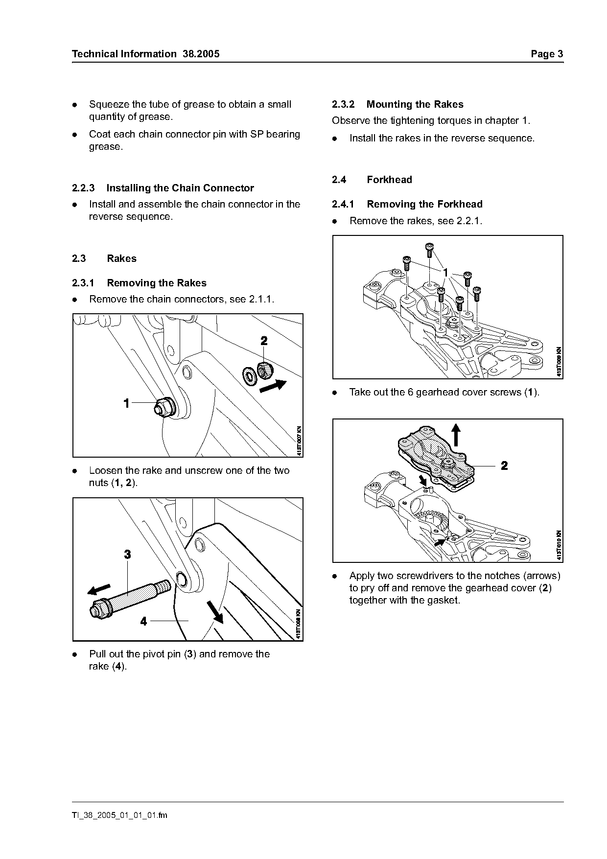
                                                        .     Take out the 6 gearhead cover screws (1).

.     Loosen the rake and unscrew one of the two
      nuts (1, 2).

                                                        .     Apply two screwdrivers to the notches (arrows)
                                                              to pry off and remove the gearhead cover (2)
                                                              together with the gasket.

.     Pull out the pivot pin (3) and remove the
      rake (4).

TI_38_2005_01_01_01.fm
Page 4 of 6
Text of page 4 — search, copy, screen readers
Page 4                                                                        Technical Information 38.2005

                                                         2.4.2     Installing the Forkhead
                                                         Observe the tightening torques in chapter 1.
                                                         .     Install the forkhead in the reverse sequence.

                                                         3.        Gearhead

                                                         3.1       Disassembling the Gearhead
                                                         .     Remove the gearhead from the drive tube.
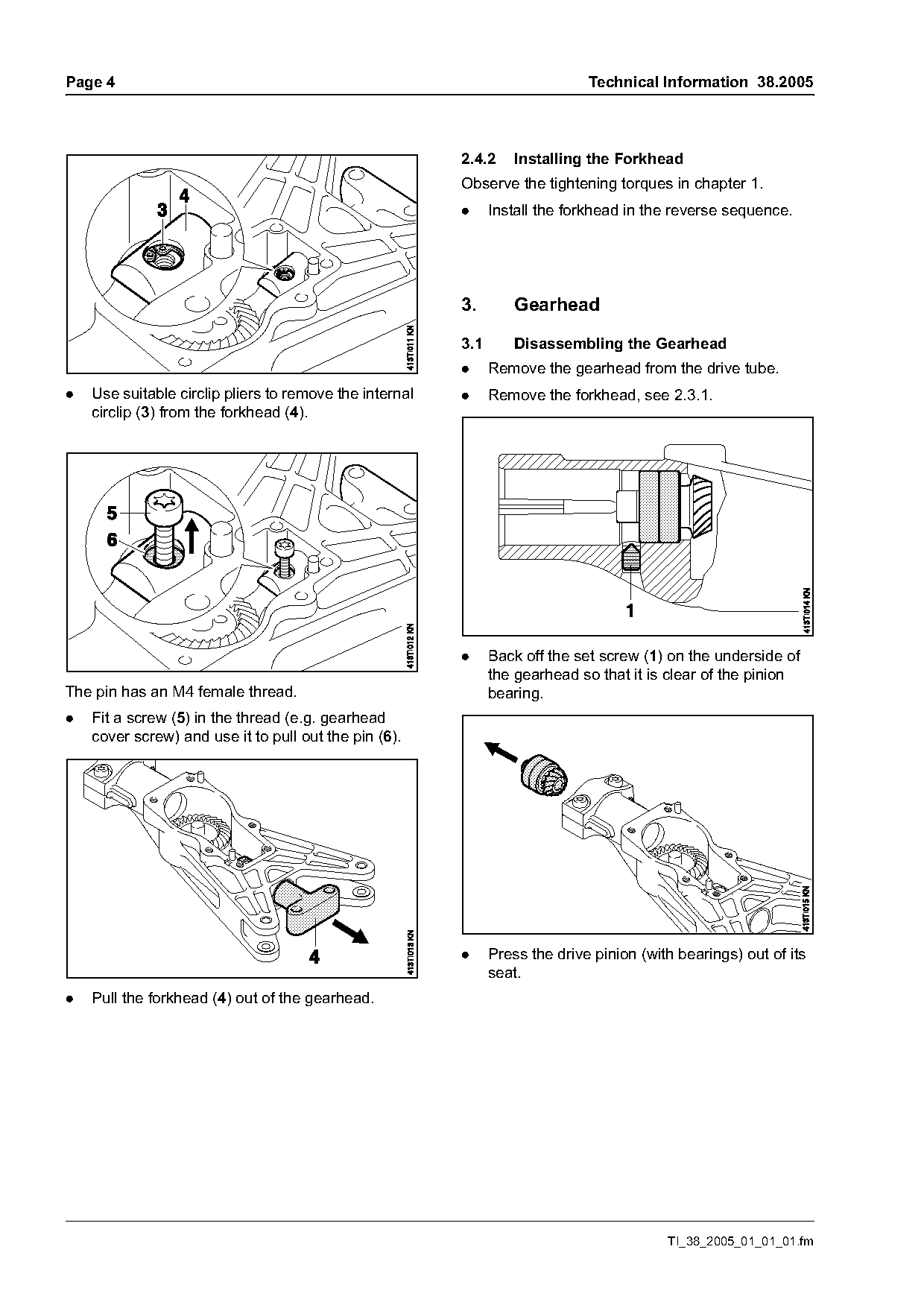
.   Use suitable circlip pliers to remove the internal   .     Remove the forkhead, see 2.3.1.
    circlip (3) from the forkhead (4).

                                                         .     Back off the set screw (1) on the underside of
                                                               the gearhead so that it is clear of the pinion
The pin has an M4 female thread.                               bearing.
.   Fit a screw (5) in the thread (e.g. gearhead
    cover screw) and use it to pull out the pin (6).

                                                         .     Press the drive pinion (with bearings) out of its
                                                               seat.
.   Pull the forkhead (4) out of the gearhead.

                                                                                          TI_38_2005_01_01_01.fm
Page 5 of 6
Text of page 5 — search, copy, screen readers
Technical Information 38.2005                                                                         Page 5

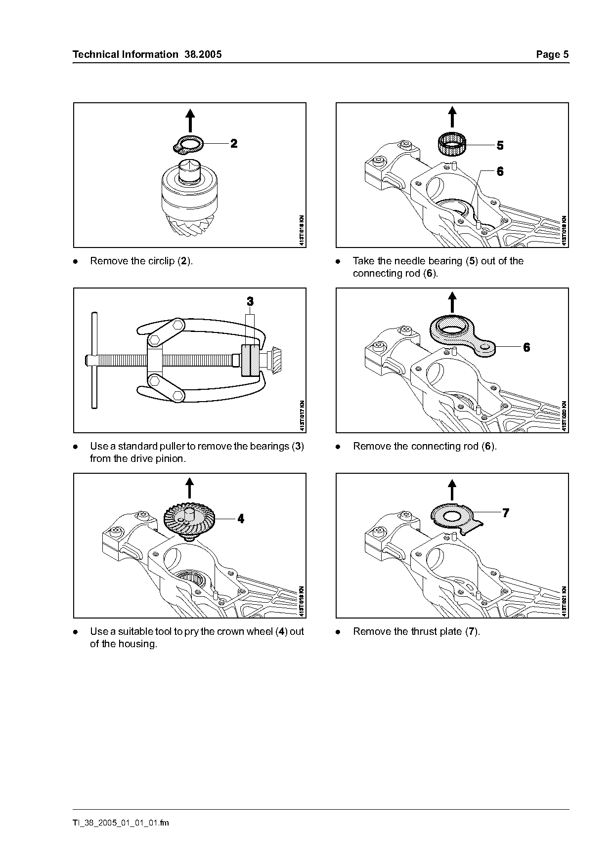
.   Remove the circlip (2).                              .   Take the needle bearing (5) out of the
                                                             connecting rod (6).

.   Use a standard puller to remove the bearings (3)     .   Remove the connecting rod (6).
    from the drive pinion.

.   Use a suitable tool to pry the crown wheel (4) out   .   Remove the thrust plate (7).
    of the housing.

TI_38_2005_01_01_01.fm
Page 6 of 6
Text of page 6 — search, copy, screen readers
Page 6                                                                          Technical Information 38.2005

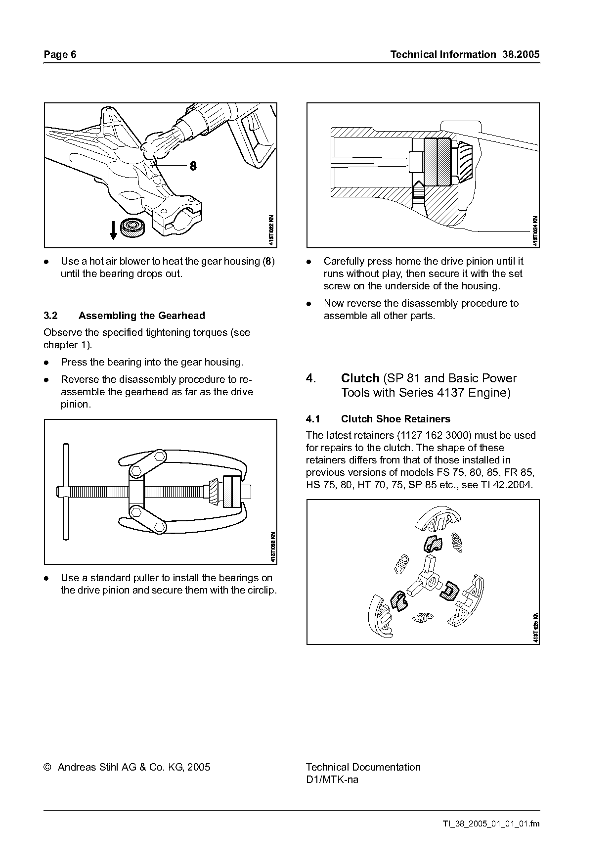
.     Use a hot air blower to heat the gear housing (8)    .     Carefully press home the drive pinion until it
      until the bearing drops out.                               runs without play, then secure it with the set
                                                                 screw on the underside of the housing.
                                                           .     Now reverse the disassembly procedure to
3.2       Assembling the Gearhead                                assemble all other parts.
Observe the specified tightening torques (see
chapter 1).
.     Press the bearing into the gear housing.
.     Reverse the disassembly procedure to re-             4.        Clutch (SP 81 and Basic Power
      assemble the gearhead as far as the drive                      Tools with Series 4137 Engine)
      pinion.
                                                           4.1       Clutch Shoe Retainers
                                                           The latest retainers (1127 162 3000) must be used
                                                           for repairs to the clutch. The shape of these
                                                           retainers differs from that of those installed in
                                                           previous versions of models FS 75, 80, 85, FR 85,
                                                           HS 75, 80, HT 70, 75, SP 85 etc., see TI 42.2004.

.     Use a standard puller to install the bearings on
      the drive pinion and secure them with the circlip.

© Andreas Stihl AG & Co. KG, 2005                          Technical Documentation
                                                           D1/MTK-na

                                                                                            TI_38_2005_01_01_01.fm
Most of these PDFs embed fonts with a shifted character map, so the text above was recovered rather than copied — read it as a faithful but imperfect transcription, and treat the page image above each block as the authority where the two disagree — the figures exist only there, because they are vector drawings that text extraction cannot keep.